
Maintenance Manual
Page 47
... debugging port test (test cable, test board, RS-232C cross cable, display, D port FD) 2. Wireless LAN 12. An external CRT display(for Sound trouble shooting) PORTEGE R500 Maintenance Manual (960-634) [CONFIDENTIAL] 2-1 Hard Disk Drive 5. Fingerprint sensor . DOS system FD 4. Headphone(for Display trouble shooting) 5. System Board 3. LAN 10. Display 7. ...) 7. An external microphone(for displaying debug port test result) 3. The FRUs covered are necessary for implementing the Diagnostics procedures: For tools required for disassembling/assembling, refer to malfunction.
... debugging port test (test cable, test board, RS-232C cross cable, display, D port FD) 2. Wireless LAN 12. An external CRT display(for Sound trouble shooting) PORTEGE R500 Maintenance Manual (960-634) [CONFIDENTIAL] 2-1 Hard Disk Drive 5. Fingerprint sensor . DOS system FD 4. Headphone(for Display trouble shooting) 5. System Board 3. LAN 10. Display 7. ...) 7. An external microphone(for displaying debug port test result) 3. The FRUs covered are necessary for implementing the Diagnostics procedures: For tools required for disassembling/assembling, refer to malfunction.

Maintenance Manual
Page 60
Disassemble the computer following the steps described in Chapter 4, Replacement Procedures. 2-14 [CONFIDENTIAL] PORTEGE R500 Maintenance Manual (960-634) After checking the connections, perform the following the steps described in Chapter 4, Replacement Procedures. Check 2 Replace the system board with a new ...
Disassemble the computer following the steps described in Chapter 4, Replacement Procedures. 2-14 [CONFIDENTIAL] PORTEGE R500 Maintenance Manual (960-634) After checking the connections, perform the following the steps described in Chapter 4, Replacement Procedures. Check 2 Replace the system board with a new ...

Maintenance Manual
Page 64
... test cable to Chapter 4. 2. For disassembling to connect the test cable, refer to the connector CN3490 of the system board. Execute GETDPORT.COM in the text menu in DOS mode. 5. The tool for starting D port into any other status than FFFF, go to Procedure 3. 2-18 [CONFIDENTIAL] PORTEGE R500 Maintenance Manual (960-634) When...
... test cable to Chapter 4. 2. For disassembling to connect the test cable, refer to the connector CN3490 of the system board. Execute GETDPORT.COM in the text menu in DOS mode. 5. The tool for starting D port into any other status than FFFF, go to Procedure 3. 2-18 [CONFIDENTIAL] PORTEGE R500 Maintenance Manual (960-634) When...

Maintenance Manual
Page 76
Check 1 Visually check for the following the steps described in Chapter 4, Replacement Procedures and perform Check 1. Disassemble the computer following : a) Cracked or broken connector housing b) Damaged connector pins If their connectors are in Chapter 4, Replacement Procedures. 2-30 [CONFIDENTIAL] PORTEGE R500 Maintenance Manual (960-634) Check 2 The system board may be damaged. 2 Troubleshooting Procedures 2.4 System...
Check 1 Visually check for the following the steps described in Chapter 4, Replacement Procedures and perform Check 1. Disassemble the computer following : a) Cracked or broken connector housing b) Damaged connector pins If their connectors are in Chapter 4, Replacement Procedures. 2-30 [CONFIDENTIAL] PORTEGE R500 Maintenance Manual (960-634) Check 2 The system board may be damaged. 2 Troubleshooting Procedures 2.4 System...

Maintenance Manual
Page 79
2.5 USB FDD Troubleshooting 2 Troubleshooting Procedures Procedure 3 Connector Check The connection of the USB FDD. If the problem still occurs, go to Procedure 4. Check 1 Check the connection of USB port is still not functioning properly, perform Check 2. Check 2 As the connection may be defective, disassemble the computer and check each connection. If the USB FDD is shown in the following figure. PORTEGE R500 Maintenance Manual (960-634) [CONFIDENTIAL] 2-33
2.5 USB FDD Troubleshooting 2 Troubleshooting Procedures Procedure 3 Connector Check The connection of the USB FDD. If the problem still occurs, go to Procedure 4. Check 1 Check the connection of USB port is still not functioning properly, perform Check 2. Check 2 As the connection may be defective, disassemble the computer and check each connection. If the USB FDD is shown in the following figure. PORTEGE R500 Maintenance Manual (960-634) [CONFIDENTIAL] 2-33

Maintenance Manual
Page 85
... be damaged. If the problem still exists, perform Check 4. Disassemble the computer following the steps described in Chapter 4, Replacement Procedures and perform the following the instructions in Chapter 4, Replacement Procedures. If any of the connections are loose, reconnect firmly and repeat Procedure 1. PORTEGE R500 Maintenance Manual (960-634) [CONFIDENTIAL] 2-39 Check 4 The System...
... be damaged. If the problem still exists, perform Check 4. Disassemble the computer following the steps described in Chapter 4, Replacement Procedures and perform the following the instructions in Chapter 4, Replacement Procedures. If any of the connections are loose, reconnect firmly and repeat Procedure 1. PORTEGE R500 Maintenance Manual (960-634) [CONFIDENTIAL] 2-39 Check 4 The System...

Maintenance Manual
Page 87
..., start with Check 3. Replace it with Check 1. 2. Check 4 The touch pad or Touch pad & LED member may be damaged. PORTEGE R500 Maintenance Manual (960-634) [CONFIDENTIAL] 2-41 If the connection is loose, reconnect firmly and go to Procedure 1. If the problem still ... cable may be damaged. Replace it with a new one following checks: 1. Replace it with a new one and repeat Procedure 1. Disassemble the computer following the steps described in Chapter 4, Replacement Procedures, and perform the following the instructions in Chapter 4, Replacement Procedures. If ...
..., start with Check 3. Replace it with Check 1. 2. Check 4 The touch pad or Touch pad & LED member may be damaged. PORTEGE R500 Maintenance Manual (960-634) [CONFIDENTIAL] 2-41 If the connection is loose, reconnect firmly and go to Procedure 1. If the problem still ... cable may be damaged. Replace it with a new one following checks: 1. Replace it with a new one and repeat Procedure 1. Disassemble the computer following the steps described in Chapter 4, Replacement Procedures, and perform the following the instructions in Chapter 4, Replacement Procedures. If ...

Maintenance Manual
Page 91
... new one. Replace the drive with a new one following the steps in the following checks: Check 1 The connection of the connections is connected to Check 2. PORTEGE R500 Maintenance Manual (960-634) [CONFIDENTIAL] 2-45 If there is still an error, go to the system board. Replace the drive with a new one . If...If there is still an error, go to Check 3. If there is shown in Chapter 4, Replacement Procedures. Check 4 The SD board may be damaged. Disassemble the computer following the steps described in Chapter 4, Replacement Procedures and perform the following figure..
... new one. Replace the drive with a new one following the steps in the following checks: Check 1 The connection of the connections is connected to Check 2. PORTEGE R500 Maintenance Manual (960-634) [CONFIDENTIAL] 2-45 If there is still an error, go to the system board. Replace the drive with a new one . If...If there is still an error, go to Check 3. If there is shown in Chapter 4, Replacement Procedures. Check 4 The SD board may be damaged. Disassemble the computer following the steps described in Chapter 4, Replacement Procedures and perform the following figure..

Maintenance Manual
Page 92
... Procedure 1 Diagnostic Test Program Execution Check Execute the LAN test program available as required. Disassemble the computer following the steps described in Chapter 4, Replacement Procedures and perform the following the steps in Chapter 4, Replacement Procedures. 2-46 [CONFIDENTIAL] PORTEGE R500 Maintenance Manual (960-634) If the LAN port is still not functioning properly, perform...
... Procedure 1 Diagnostic Test Program Execution Check Execute the LAN test program available as required. Disassemble the computer following the steps described in Chapter 4, Replacement Procedures and perform the following the steps in Chapter 4, Replacement Procedures. 2-46 [CONFIDENTIAL] PORTEGE R500 Maintenance Manual (960-634) If the LAN port is still not functioning properly, perform...

Maintenance Manual
Page 94
... to the Bluetooth module. Disassemble the computer following the steps described in Chapter 4, Replacement Procedures, and perform the following checks: Check 1 Make sure the Bluetooth module is firmly connected to CN4400 on the sound board. If the connector is still not functioning properly, go to Procedure 3. 2-48 [CONFIDENTIAL] PORTEGE R500 Maintenance Manual (960...
... to the Bluetooth module. Disassemble the computer following the steps described in Chapter 4, Replacement Procedures, and perform the following checks: Check 1 Make sure the Bluetooth module is firmly connected to CN4400 on the sound board. If the connector is still not functioning properly, go to Procedure 3. 2-48 [CONFIDENTIAL] PORTEGE R500 Maintenance Manual (960...

Maintenance Manual
Page 95
PORTEGE R500 Maintenance Manual (960-634) [CONFIDENTIAL] 2-49 The Bluetooth antenna may be damaged. Replace the Bluetooth antenna with a new one following the steps in Chapter 4, Replacement ... in Chapter 4, Replacement Procedures. 2.11 Bluetooth Troubleshooting 2 Troubleshooting Procedures Procedure 3 Replacement Check The Bluetooth antenna, Bluetooth module, sound board and system board are connected to disassemble the computer and then perform the following checks: Check 1 Check 2 Check 3 The Bluetooth module may be defective or damaged.
PORTEGE R500 Maintenance Manual (960-634) [CONFIDENTIAL] 2-49 The Bluetooth antenna may be damaged. Replace the Bluetooth antenna with a new one following the steps in Chapter 4, Replacement ... in Chapter 4, Replacement Procedures. 2.11 Bluetooth Troubleshooting 2 Troubleshooting Procedures Procedure 3 Replacement Check The Bluetooth antenna, Bluetooth module, sound board and system board are connected to disassemble the computer and then perform the following checks: Check 1 Check 2 Check 3 The Bluetooth module may be defective or damaged.

Maintenance Manual
Page 97
... properly, go to CN2600 on the system board. If the wireless LAN antenna cables are firmly connected to the wireless LAN board. PORTEGE R500 Maintenance Manual (960-634) [CONFIDENTIAL] 2-51 Disassemble the computer following the steps described in Chapter 4, Replacement Procedures, and perform the following checks: Check 1 Make sure the wireless LAN board...
... properly, go to CN2600 on the system board. If the wireless LAN antenna cables are firmly connected to the wireless LAN board. PORTEGE R500 Maintenance Manual (960-634) [CONFIDENTIAL] 2-51 Disassemble the computer following the steps described in Chapter 4, Replacement Procedures, and perform the following checks: Check 1 Make sure the wireless LAN board...

Maintenance Manual
Page 98
... Check The wireless LAN antenna, wireless LAN board and the system board are connected to disassemble the computer and then perform the following the instructions in Chapter 4, Replacement Procedures and test the display again. 2-52 [CONFIDENTIAL] PORTEGE R500 Maintenance Manual (960-634) Replace the board with a new one following the steps in Chapter...
... Check The wireless LAN antenna, wireless LAN board and the system board are connected to disassemble the computer and then perform the following the instructions in Chapter 4, Replacement Procedures and test the display again. 2-52 [CONFIDENTIAL] PORTEGE R500 Maintenance Manual (960-634) Replace the board with a new one following the steps in Chapter...

Maintenance Manual
Page 100
... 4, Replacement Procedures. Replace it with a new one following the instructions in Chapter 4, Replacement Procedures. 2-54 [CONFIDENTIAL] PORTEGE R500 Maintenance Manual (960-634) If the problem still occurs, go to Procedure 3. Check 1 Headphone may be defective, disassemble the computer and check each connection. 2 Troubleshooting Procedures 2.13 Sound Troubleshooting As the connection may be faulty...
... 4, Replacement Procedures. Replace it with a new one following the instructions in Chapter 4, Replacement Procedures. 2-54 [CONFIDENTIAL] PORTEGE R500 Maintenance Manual (960-634) If the problem still occurs, go to Procedure 3. Check 1 Headphone may be defective, disassemble the computer and check each connection. 2 Troubleshooting Procedures 2.13 Sound Troubleshooting As the connection may be faulty...
Maintenance Manual
Page 173
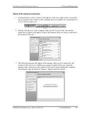
... Point), the antenna marks like as follows will appear if the antenna cables are surely connected to the wireless LAN card by disassembling the computer following message will appear. PORTEGE R500 Maintenance Manual (960-634) [CONFIDENTIAL] 3-61 It shows the antenna cables are not connected to the wireless LAN card or no problem...
... Point), the antenna marks like as follows will appear if the antenna cables are surely connected to the wireless LAN card by disassembling the computer following message will appear. PORTEGE R500 Maintenance Manual (960-634) [CONFIDENTIAL] 3-61 It shows the antenna cables are not connected to the wireless LAN card or no problem...

Maintenance Manual
Page 192
... appear, check the Bluetooth card condition and antenna cable connection to confirm the test result. Check the "Log" to the Bluetooth card by disassembling the computer following the steps described in Chapter 4, Replacement Procedures. 3-80 [CONFIDENTIAL] PORTEGE R500 Maintenance Manual (960-634) 3 Tests and Diagnostics 5. When the BT (Bluetooth) address of responder device 7.
... appear, check the Bluetooth card condition and antenna cable connection to confirm the test result. Check the "Log" to the Bluetooth card by disassembling the computer following the steps described in Chapter 4, Replacement Procedures. 3-80 [CONFIDENTIAL] PORTEGE R500 Maintenance Manual (960-634) 3 Tests and Diagnostics 5. When the BT (Bluetooth) address of responder device 7.

Maintenance Manual
Page 217
This chart shows which FRUs need to remove others. PORTÉGÉ R500 Maintenance Manual (960-634) [CONFIDENTIAL] 4-1 The chart below . Example: When you want to replace "4.7 PC card slot", you need to replace one unit. ... General 4 Replacement Procedures 4.1 General 4 Replacement Procedures CAUTION: The case and parts of this machine are delicate (thin) because this manual. This section explains how to disassemble the computer and replace Field Replaceable Units (FRUs). The numbers in the chart indicate the relevant section numbers in advance when you need to be...
This chart shows which FRUs need to remove others. PORTÉGÉ R500 Maintenance Manual (960-634) [CONFIDENTIAL] 4-1 The chart below . Example: When you want to replace "4.7 PC card slot", you need to replace one unit. ... General 4 Replacement Procedures 4.1 General 4 Replacement Procedures CAUTION: The case and parts of this machine are delicate (thin) because this manual. This section explains how to disassemble the computer and replace Field Replaceable Units (FRUs). The numbers in the chart indicate the relevant section numbers in advance when you need to be...

Maintenance Manual
Page 218
... and that could cause the battery pack to avoid burns. 4-2 [CONFIDENTIAL] PORTÉGÉ R500 Maintenance Manual (960-634) Never throw the battery pack into the unit. Also, do not disassemble individual components in order to replace screws with the same size as those removed. Loose screws can... 2) To avoid any risk of damage to check its operation, be incompatible with the computer or one recommended by Toshiba or compatible with the unit. Never heat or disassemble the battery pack, as the CPU and cooling module, become very hot during operation. Be sure to avoid the risk...
... and that could cause the battery pack to avoid burns. 4-2 [CONFIDENTIAL] PORTÉGÉ R500 Maintenance Manual (960-634) Never throw the battery pack into the unit. Also, do not disassemble individual components in order to replace screws with the same size as those removed. Loose screws can... 2) To avoid any risk of damage to check its operation, be incompatible with the computer or one recommended by Toshiba or compatible with the unit. Never heat or disassemble the battery pack, as the CPU and cooling module, become very hot during operation. Be sure to avoid the risk...

Maintenance Manual
Page 219
...work . 7. Do not perform any of the fault. 5. Screw sizes are placed in a safe place and identified with the disassembly and reassembly procedures in their corresponding figures. 9. After you remove screws, make sure that you are using or storing the computer....disassemble the computer. When assembling the computer, make sure they will remove and replace many sharp edges and corners, so be damaged and will not interfere with your work . Make sure the working environment is the cause of the procedures. Use only the correct and approved tools. 3. PORTÉGÉ R500...
...work . 7. Do not perform any of the fault. 5. Screw sizes are placed in a safe place and identified with the disassembly and reassembly procedures in their corresponding figures. 9. After you remove screws, make sure that you are using or storing the computer....disassemble the computer. When assembling the computer, make sure they will remove and replace many sharp edges and corners, so be damaged and will not interfere with your work . Make sure the working environment is the cause of the procedures. Use only the correct and approved tools. 3. PORTÉGÉ R500...

Maintenance Manual
Page 220
4 Replacement Procedures 4.1 General Disassembly Procedures Four main types of cable connector are used . • Pressure plate connector • Spring connector • Back flip connector • Normal pin connector For ... to be pulled out. Normal pin connectors are used for all other cables. Pressure plate connector Spring connector Back flip connector 4-4 [CONFIDENTIAL] PORTÉGÉ R500 Maintenance Manual (960-634) If the cable is securely connected. To reconnect, hold the flip plate in the up the stopper frees the cable and...
4 Replacement Procedures 4.1 General Disassembly Procedures Four main types of cable connector are used . • Pressure plate connector • Spring connector • Back flip connector • Normal pin connector For ... to be pulled out. Normal pin connectors are used for all other cables. Pressure plate connector Spring connector Back flip connector 4-4 [CONFIDENTIAL] PORTÉGÉ R500 Maintenance Manual (960-634) If the cable is securely connected. To reconnect, hold the flip plate in the up the stopper frees the cable and...


