
Maintenance Manual
Page 47
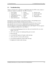
Wireless LAN 12. Fingerprint sensor . For tools required for disassembling/assembling, refer to malfunction. A PC with a serial port (for Sound trouble shooting) 7. An external microphone(for displaying debug port test result) 3....board, RS-232C cross cable, display, D port FD) 2. USB Floppy Disk Drive 4. Keyboard/Dual point 6. An external CRT display(for Sound trouble shooting) PORTEGE R500 Maintenance Manual (960-634) [CONFIDENTIAL] 2-1 Display 7. Optical Drive 8. System Board 3. Sound components 13. The FRUs covered are given in Chapter 4, Replacement Procedures...
Wireless LAN 12. Fingerprint sensor . For tools required for disassembling/assembling, refer to malfunction. A PC with a serial port (for Sound trouble shooting) 7. An external microphone(for displaying debug port test result) 3....board, RS-232C cross cable, display, D port FD) 2. USB Floppy Disk Drive 4. Keyboard/Dual point 6. An external CRT display(for Sound trouble shooting) PORTEGE R500 Maintenance Manual (960-634) [CONFIDENTIAL] 2-1 Display 7. Optical Drive 8. System Board 3. Sound components 13. The FRUs covered are given in Chapter 4, Replacement Procedures...

Maintenance Manual
Page 60
... . Check 2 Replace the system board with a new one following the steps described in Chapter 4, Replacement Procedures. 2-14 [CONFIDENTIAL] PORTEGE R500 Maintenance Manual (960-634) 2 Troubleshooting Procedures 2.3 Power Supply Troubleshooting Procedure 5 Replacement Check The system board processor module may be disconnected or damaged. Disassemble the computer following the steps described in Chapter 4, Replacement Procedures.
... . Check 2 Replace the system board with a new one following the steps described in Chapter 4, Replacement Procedures. 2-14 [CONFIDENTIAL] PORTEGE R500 Maintenance Manual (960-634) 2 Troubleshooting Procedures 2.3 Power Supply Troubleshooting Procedure 5 Replacement Check The system board processor module may be disconnected or damaged. Disassemble the computer following the steps described in Chapter 4, Replacement Procedures.

Maintenance Manual
Page 64
... D port status falls into FDD and input "FD starting D port into any other status than FFFF, go to Procedure 3. 2-18 [CONFIDENTIAL] PORTEGE R500 Maintenance Manual (960-634) Connect the debug port test cable to the PC that displays the test results. 4. 2 Troubleshooting Procedures 2.4 System Board Troubleshooting... the text menu in CPU REAL mode. (Insert the FD for serial port test is FFFF (normal status), go to Procedure 4. For disassembling to connect the test cable, refer to the test board. 3. Boot the compute1r in the following form; 6. The tool for starting drive...
... D port status falls into FDD and input "FD starting D port into any other status than FFFF, go to Procedure 3. 2-18 [CONFIDENTIAL] PORTEGE R500 Maintenance Manual (960-634) Connect the debug port test cable to the PC that displays the test results. 4. 2 Troubleshooting Procedures 2.4 System Board Troubleshooting... the text menu in CPU REAL mode. (Insert the FD for serial port test is FFFF (normal status), go to Procedure 4. For disassembling to connect the test cable, refer to the test board. 3. Boot the compute1r in the following form; 6. The tool for starting drive...

Maintenance Manual
Page 76
..., go to Check 2. Check 1 Visually check for the following the steps described in Chapter 4, Replacement Procedures and perform Check 1. Disassemble the computer following the steps described in Chapter 4, Replacement Procedures. 2-30 [CONFIDENTIAL] PORTEGE R500 Maintenance Manual (960-634) Check 2 The system board may be damaged. 2 Troubleshooting Procedures 2.4 System Board Troubleshooting Procedure 4 Replacement Check...
..., go to Check 2. Check 1 Visually check for the following the steps described in Chapter 4, Replacement Procedures and perform Check 1. Disassemble the computer following the steps described in Chapter 4, Replacement Procedures. 2-30 [CONFIDENTIAL] PORTEGE R500 Maintenance Manual (960-634) Check 2 The system board may be damaged. 2 Troubleshooting Procedures 2.4 System Board Troubleshooting Procedure 4 Replacement Check...

Maintenance Manual
Page 79
Check 1 Check the connection of USB port is still not functioning properly, perform Check 2. Check 2 As the connection may be defective, disassemble the computer and check each connection. If the problem still occurs, go to Procedure 4. PORTEGE R500 Maintenance Manual (960-634) [CONFIDENTIAL] 2-33 If the USB FDD is shown in the following figure. 2.5 USB FDD Troubleshooting 2 Troubleshooting Procedures Procedure 3 Connector Check The connection of the USB FDD.
Check 1 Check the connection of USB port is still not functioning properly, perform Check 2. Check 2 As the connection may be defective, disassemble the computer and check each connection. If the problem still occurs, go to Procedure 4. PORTEGE R500 Maintenance Manual (960-634) [CONFIDENTIAL] 2-33 If the USB FDD is shown in the following figure. 2.5 USB FDD Troubleshooting 2 Troubleshooting Procedures Procedure 3 Connector Check The connection of the USB FDD.

Maintenance Manual
Page 85
... Procedure 5 Connector Check and Replacement Check The HDD may be disconnected, or the HDD, HDD FPC or system board may be damaged. PORTEGE R500 Maintenance Manual (960-634) [CONFIDENTIAL] 2-39 If the problem still exists, perform Check 3. If there is firmly connected to Check 2. Replace ... sure the HDD is still an error, go to CN1800 on the system board. Check 4 The System board may be damaged. Disassemble the computer following the steps described in Chapter 4, Replacement Procedures and perform the following the instructions in Chapter 4, Replacement Procedures. If ...
... Procedure 5 Connector Check and Replacement Check The HDD may be disconnected, or the HDD, HDD FPC or system board may be damaged. PORTEGE R500 Maintenance Manual (960-634) [CONFIDENTIAL] 2-39 If the problem still exists, perform Check 3. If there is firmly connected to Check 2. Replace ... sure the HDD is still an error, go to CN1800 on the system board. Check 4 The System board may be damaged. Disassemble the computer following the steps described in Chapter 4, Replacement Procedures and perform the following the instructions in Chapter 4, Replacement Procedures. If ...

Maintenance Manual
Page 87
Disassemble the computer following the steps described in Chapter 4, Replacement Procedures. Check 1 Make sure the keyboard cable is securely connected to CN9850 on the system board. ... there is still an error, go to Procedure 1. If the keyboard malfunctions, start with Check 1. 2. If the connection is still an error, go to Check 4. PORTEGE R500 Maintenance Manual (960-634) [CONFIDENTIAL] 2-41 If there is loose, reconnect firmly and go to Check5. 2.7 Keyboard and Dual point Troubleshooting 2 Troubleshooting Procedures Procedure 2 Connector...
Disassemble the computer following the steps described in Chapter 4, Replacement Procedures. Check 1 Make sure the keyboard cable is securely connected to CN9850 on the system board. ... there is still an error, go to Procedure 1. If the keyboard malfunctions, start with Check 1. 2. If the connection is still an error, go to Check 4. PORTEGE R500 Maintenance Manual (960-634) [CONFIDENTIAL] 2-41 If there is loose, reconnect firmly and go to Check5. 2.7 Keyboard and Dual point Troubleshooting 2 Troubleshooting Procedures Procedure 2 Connector...

Maintenance Manual
Page 91
... damaged. Replace the drive with a new one. PORTEGE R500 Maintenance Manual (960-634) [CONFIDENTIAL] 2-45 Check 4 The SD board may be defective or damaged. If there is still an error, go to the system board. If there is still an error, go to Check 5. Disassemble the computer following the steps described in Chapter...
... damaged. Replace the drive with a new one. PORTEGE R500 Maintenance Manual (960-634) [CONFIDENTIAL] 2-45 Check 4 The SD board may be defective or damaged. If there is still an error, go to the system board. If there is still an error, go to Check 5. Disassemble the computer following the steps described in Chapter...

Maintenance Manual
Page 92
... test program. If the LAN malfunctions, the system board might be defective or damaged. Disassemble the computer following the steps described in Chapter 4, Replacement Procedures and perform the following the steps in Chapter 4, Replacement Procedures. 2-46 [CONFIDENTIAL] PORTEGE R500 Maintenance Manual (960-634) Check 2 The RJ-45 jack may be damaged. If the...
... test program. If the LAN malfunctions, the system board might be defective or damaged. Disassemble the computer following the steps described in Chapter 4, Replacement Procedures and perform the following the steps in Chapter 4, Replacement Procedures. 2-46 [CONFIDENTIAL] PORTEGE R500 Maintenance Manual (960-634) Check 2 The RJ-45 jack may be damaged. If the...

Maintenance Manual
Page 94
If the Bluetooth module is firmly connected to CN4400 on the sound board. Disassemble the computer following the steps described in Chapter 4, Replacement Procedures, and perform the following checks: Check 1 Make sure the Bluetooth module is still not functioning ... Bluetooth module. If the Bluetooth module is disconnected, connect it firmly. Check 2 Make sure the Bluetooth antenna cable is firmly connected to Procedure 3. 2-48 [CONFIDENTIAL] PORTEGE R500 Maintenance Manual (960-634)
If the Bluetooth module is firmly connected to CN4400 on the sound board. Disassemble the computer following the steps described in Chapter 4, Replacement Procedures, and perform the following checks: Check 1 Make sure the Bluetooth module is still not functioning ... Bluetooth module. If the Bluetooth module is disconnected, connect it firmly. Check 2 Make sure the Bluetooth antenna cable is firmly connected to Procedure 3. 2-48 [CONFIDENTIAL] PORTEGE R500 Maintenance Manual (960-634)

Maintenance Manual
Page 95
... functioning properly, perform Check 3. Replace the Bluetooth antenna with a new one following the steps in Chapter 4, Replacement Procedures. PORTEGE R500 Maintenance Manual (960-634) [CONFIDENTIAL] 2-49 Refer to Chapter 4, Replacement Procedures, for instructions on how to the circuits.... Troubleshooting 2 Troubleshooting Procedures Procedure 3 Replacement Check The Bluetooth antenna, Bluetooth module, sound board and system board are connected to disassemble the computer and then perform the following checks: Check 1 Check 2 Check 3 The Bluetooth module may be defective or damaged...
... functioning properly, perform Check 3. Replace the Bluetooth antenna with a new one following the steps in Chapter 4, Replacement Procedures. PORTEGE R500 Maintenance Manual (960-634) [CONFIDENTIAL] 2-49 Refer to Chapter 4, Replacement Procedures, for instructions on how to the circuits.... Troubleshooting 2 Troubleshooting Procedures Procedure 3 Replacement Check The Bluetooth antenna, Bluetooth module, sound board and system board are connected to disassemble the computer and then perform the following checks: Check 1 Check 2 Check 3 The Bluetooth module may be defective or damaged...

Maintenance Manual
Page 97
PORTEGE R500 Maintenance Manual (960-634) [CONFIDENTIAL] 2-51 If the wireless LAN antenna cables are firmly connected to the wireless LAN board. Check 2 Make sure the wireless LAN antenna cables are disconnected, connect them firmly. If the connector is firmly connected to Procedure 3. Disassemble the computer following the steps described in Chapter 4, Replacement Procedures...
PORTEGE R500 Maintenance Manual (960-634) [CONFIDENTIAL] 2-51 If the wireless LAN antenna cables are firmly connected to the wireless LAN board. Check 2 Make sure the wireless LAN antenna cables are disconnected, connect them firmly. If the connector is firmly connected to Procedure 3. Disassemble the computer following the steps described in Chapter 4, Replacement Procedures...

Maintenance Manual
Page 98
...the board with a new one following the instructions in Chapter 4, Replacement Procedures and test the display again. 2-52 [CONFIDENTIAL] PORTEGE R500 Maintenance Manual (960-634) The wireless LAN antenna may be damaged. Replace the board with a new one following the steps... 2.12 Wireless LAN Troubleshooting Procedure 3 Replacement Check The wireless LAN antenna, wireless LAN board and the system board are connected to disassemble the computer and then perform the following the steps in Chapter 4, Replacement Procedures. The system board may be defective or damaged. If...
...the board with a new one following the instructions in Chapter 4, Replacement Procedures and test the display again. 2-52 [CONFIDENTIAL] PORTEGE R500 Maintenance Manual (960-634) The wireless LAN antenna may be damaged. Replace the board with a new one following the steps... 2.12 Wireless LAN Troubleshooting Procedure 3 Replacement Check The wireless LAN antenna, wireless LAN board and the system board are connected to disassemble the computer and then perform the following the steps in Chapter 4, Replacement Procedures. The system board may be defective or damaged. If...

Maintenance Manual
Page 100
... it with a new one following the steps in Chapter 4, Replacement Procedures. 2-54 [CONFIDENTIAL] PORTEGE R500 Maintenance Manual (960-634) If the problem still occurs, perform Check 5. If the problem still occurs, perform Check 6 Check 6 System board may be defective, disassemble the computer and check each connection. 2 Troubleshooting Procedures 2.13 Sound Troubleshooting As the...
... it with a new one following the steps in Chapter 4, Replacement Procedures. 2-54 [CONFIDENTIAL] PORTEGE R500 Maintenance Manual (960-634) If the problem still occurs, perform Check 5. If the problem still occurs, perform Check 6 Check 6 System board may be defective, disassemble the computer and check each connection. 2 Troubleshooting Procedures 2.13 Sound Troubleshooting As the...
Maintenance Manual
Page 173
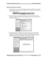
...-click the icon. PORTEGE R500 Maintenance Manual (960-634) [CONFIDENTIAL] 3-61 The following the steps described in Chapter 4, Replacement Procedures. If the computer finds any AP (Access Point), the antenna marks like as follows will appear if the antenna cables are surely connected to the wireless LAN card by disassembling the computer following...
...-click the icon. PORTEGE R500 Maintenance Manual (960-634) [CONFIDENTIAL] 3-61 The following the steps described in Chapter 4, Replacement Procedures. If the computer finds any AP (Access Point), the antenna marks like as follows will appear if the antenna cables are surely connected to the wireless LAN card by disassembling the computer following...

Maintenance Manual
Page 192
... does not appear, check the Bluetooth card condition and antenna cable connection to confirm the test result. Check the "Log" to the Bluetooth card by disassembling the computer following the steps described in Chapter 4, Replacement Procedures. 3-80 [CONFIDENTIAL] PORTEGE R500 Maintenance Manual (960-634)
... does not appear, check the Bluetooth card condition and antenna cable connection to confirm the test result. Check the "Log" to the Bluetooth card by disassembling the computer following the steps described in Chapter 4, Replacement Procedures. 3-80 [CONFIDENTIAL] PORTEGE R500 Maintenance Manual (960-634)

Maintenance Manual
Page 217
... (thin) because this manual. The chart below . It may not be removed. PORTÉGÉ R500 Maintenance Manual (960-634) [CONFIDENTIAL] 4-1 Refer to the example of installing/removing. This chart shows which FRUs need to disassemble the computer and replace Field Replaceable Units (FRUs). Handle with care of the chart described below...
... (thin) because this manual. The chart below . It may not be removed. PORTÉGÉ R500 Maintenance Manual (960-634) [CONFIDENTIAL] 4-1 Refer to the example of installing/removing. This chart shows which FRUs need to disassemble the computer and replace Field Replaceable Units (FRUs). Handle with care of the chart described below...

Maintenance Manual
Page 218
... you change a component, be very careful not to touch connectors or components, in order to avoid burns. 4-2 [CONFIDENTIAL] PORTÉGÉ R500 Maintenance Manual (960-634) Never work after they may burst or explode. Remove any metal objects such as screws or paper clips to fall into...the cable that came with the unit, and may be incompatible with the computer or one recommended by Toshiba or compatible with the same size as those removed. Also, do not disassemble individual components in order to reduce the risk of electric shock. WARNING: 1) Turn off the power...
... you change a component, be very careful not to touch connectors or components, in order to avoid burns. 4-2 [CONFIDENTIAL] PORTÉGÉ R500 Maintenance Manual (960-634) Never work after they may burst or explode. Remove any metal objects such as screws or paper clips to fall into...the cable that came with the unit, and may be incompatible with the computer or one recommended by Toshiba or compatible with the same size as those removed. Also, do not disassemble individual components in order to reduce the risk of electric shock. WARNING: 1) Turn off the power...

Maintenance Manual
Page 219
...sure the working environment is the cause of the fault. 5. Screw sizes are listed in section "4.2 Battery Pack". 1. PORTÉGÉ R500 Maintenance Manual (960-634) [CONFIDENTIAL] 4-3 After removing parts from the computer, place them in this manual. 6. When you remove screws... assembling the computer, make sure the computer is operating abnormally. 2. Always work . 7. The computer contains many screws when you disassemble the computer. Always remove the AC adapter and battery pack before starting work . Perform the diagnostic tests described in place. After...
...sure the working environment is the cause of the fault. 5. Screw sizes are listed in section "4.2 Battery Pack". 1. PORTÉGÉ R500 Maintenance Manual (960-634) [CONFIDENTIAL] 4-3 After removing parts from the computer, place them in this manual. 6. When you remove screws... assembling the computer, make sure the computer is operating abnormally. 2. Always work . 7. The computer contains many screws when you disassemble the computer. Always remove the AC adapter and battery pack before starting work . Perform the diagnostic tests described in place. After...

Maintenance Manual
Page 220
...Pull the cable to ensure that you lift the pressure plate high enough to ensure that it is securely connected. 4 Replacement Procedures 4.1 General Disassembly Procedures Four main types of cable connector are used . • Pressure plate connector • Spring connector • Back flip connector &#... pin connectors are used for all other cables. Pressure plate connector Spring connector Back flip connector 4-4 [CONFIDENTIAL] PORTÉGÉ R500 Maintenance Manual (960-634) Simply pull out or push in the up position and insert the cable, then lower the stopper to...
...Pull the cable to ensure that you lift the pressure plate high enough to ensure that it is securely connected. 4 Replacement Procedures 4.1 General Disassembly Procedures Four main types of cable connector are used . • Pressure plate connector • Spring connector • Back flip connector &#... pin connectors are used for all other cables. Pressure plate connector Spring connector Back flip connector 4-4 [CONFIDENTIAL] PORTÉGÉ R500 Maintenance Manual (960-634) Simply pull out or push in the up position and insert the cable, then lower the stopper to...


