User Manual
Page 165
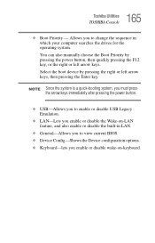
... arrow keys immediately after pressing the power button. ❖ USB-Allows you to view current BIOS. ❖ Device Config-Shows the Device configuration options. ❖ Keyboard-lets you enable or disable the Wake-on -keyboard. 165 Toshiba Utilities TOSHIBA Console ❖ Boot Priority - You can also manually choose the Boot Priority by pressing...
... arrow keys immediately after pressing the power button. ❖ USB-Allows you to view current BIOS. ❖ Device Config-Shows the Device configuration options. ❖ Keyboard-lets you enable or disable the Wake-on -keyboard. 165 Toshiba Utilities TOSHIBA Console ❖ Boot Priority - You can also manually choose the Boot Priority by pressing...
User Manual
Page 181
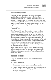
... the new device. For an older device, remove it . Resolving conflicts There are three things you install an older (legacy) device that helps the system BIOS (basic input/output system) and the operating system to automatically assign system resources to bypass the microprocessor and access memory directly. 181 If Something Goes...
... the new device. For an older device, remove it . Resolving conflicts There are three things you install an older (legacy) device that helps the system BIOS (basic input/output system) and the operating system to automatically assign system resources to bypass the microprocessor and access memory directly. 181 If Something Goes...
User Manual
Page 221
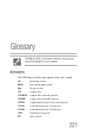
Glossary TECHNICAL NOTE: Some features defined in this glossary may appear in this user's guide. AC alternating current BIOS basic input/output system bps bits per second CD compact disc CD-ROM compact disc read-only memory CD-RW compact disc rewritable memory CMOS complementary metal-oxide semiconductor COM1 communications port 1 (serial port) COM2 communications port 2 (serial port) CPU central processing unit DC direct current 221 Acronyms The following acronyms may not be available on your computer.
Glossary TECHNICAL NOTE: Some features defined in this glossary may appear in this user's guide. AC alternating current BIOS basic input/output system bps bits per second CD compact disc CD-ROM compact disc read-only memory CD-RW compact disc rewritable memory CMOS complementary metal-oxide semiconductor COM1 communications port 1 (serial port) COM2 communications port 2 (serial port) CPU central processing unit DC direct current 221 Acronyms The following acronyms may not be available on your computer.
User Manual
Page 224
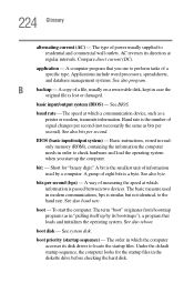
.... See also baud rate. boot - baud rate - boot priority (startup sequence) - 224 Glossary alternating current (AC) - basic input/output system (BIOS) - Short for the startup files in "pulling itself up the computer. The term "boot" originates from bootstrap program (as a printer or modem, ..."binary digit." Compare direct current (DC). A way of power usually supplied to residential and commercial wall outlets. See BIOS. See also bits per second (bps) - BIOS (basic input/output system) - To start up by a computer. See also reboot. B backup -
.... See also baud rate. boot - baud rate - boot priority (startup sequence) - 224 Glossary alternating current (AC) - basic input/output system (BIOS) - Short for the startup files in "pulling itself up the computer. The term "boot" originates from bootstrap program (as a printer or modem, ..."binary digit." Compare direct current (DC). A way of power usually supplied to residential and commercial wall outlets. See BIOS. See also bits per second (bps) - BIOS (basic input/output system) - To start up by a computer. See also reboot. B backup -
User Manual
Page 234
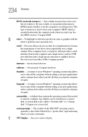
See also BIOS, memory. Processes that allows you to turn the computer on again. Standby - A system disk is receiving power. This type of some Windows® operating systems ... of some operation on again. software - A feature of memory is essential instructions the computer reads when you turn off the computer without exiting your computer's BIOS, which provides a high-speed connection to multiple devices. A diskette that information in the MS-DOS® operating system, generally a drive letter followed by a "greater than...
See also BIOS, memory. Processes that allows you to turn the computer on again. Standby - A system disk is receiving power. This type of some Windows® operating systems ... of some operation on again. software - A feature of memory is essential instructions the computer reads when you turn off the computer without exiting your computer's BIOS, which provides a high-speed connection to multiple devices. A diskette that information in the MS-DOS® operating system, generally a drive letter followed by a "greater than...
Maintenance Manual
Page 4
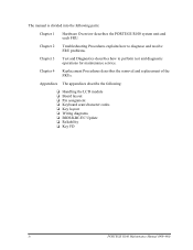
... LCD module ❑ Board layout ❑ Pin assignment ❑ Keyboard scan/character codes ❑ Key layout ❑ Wiring diagrams ❑ BIOS/KBC/EC Update ❑ Reliability ❑ Key FD iv PORTEGE R100 Maintenance Manual (960-440) Chapter 4 Replacement Procedures describes the removal and replacement of the FRUs. Chapter 2 Troubleshooting Procedures explains how to...
... LCD module ❑ Board layout ❑ Pin assignment ❑ Keyboard scan/character codes ❑ Key layout ❑ Wiring diagrams ❑ BIOS/KBC/EC Update ❑ Reliability ❑ Key FD iv PORTEGE R100 Maintenance Manual (960-440) Chapter 4 Replacement Procedures describes the removal and replacement of the FRUs. Chapter 2 Troubleshooting Procedures explains how to...
Maintenance Manual
Page 8
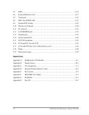
... Lamp...4-50 Appendices Appendix A Appendix B Appendix C Appendix D Appendix E Appendix F Appendix G Appendix H Handling the LCD Module A-1 Board Layout B-1 Pin Assignment C-1 Keyboard Scan/Character Codes D-1 Key Layout E-1 BIOS/KBC/EC Update F-1 Reliability G-1 Key FD...H-1 viii PORTEGE R100 Maintenance Manual (960-440)
... Lamp...4-50 Appendices Appendix A Appendix B Appendix C Appendix D Appendix E Appendix F Appendix G Appendix H Handling the LCD Module A-1 Board Layout B-1 Pin Assignment C-1 Keyboard Scan/Character Codes D-1 Key Layout E-1 BIOS/KBC/EC Update F-1 Reliability G-1 Key FD...H-1 viii PORTEGE R100 Maintenance Manual (960-440)
Maintenance Manual
Page 18
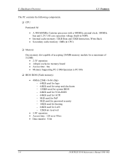
...; 2.5V operation • 140-pin exclusive memory board • Access time : 6ns • Memory Supporting PC-2100(Operation is PC100) ❑ BIOS ROM (Flash memory) • 4Mbit (256K×16-bit chip) − 64KB used for logo − 64KB used for setup and checksum −...BIOS − 64KB used for VGA-BIOS − 64KB used for ACPI − 8KB used for PnP − 8KB used for password security − 16KB used for booting − 64KB used for LAN − 32KB are reserved • 5.0V operation • Access time : 120 ns or 90 ns • Data transfer: 8-bit 1-6 PORTEGE R100...
...; 2.5V operation • 140-pin exclusive memory board • Access time : 6ns • Memory Supporting PC-2100(Operation is PC100) ❑ BIOS ROM (Flash memory) • 4Mbit (256K×16-bit chip) − 64KB used for logo − 64KB used for setup and checksum −...BIOS − 64KB used for VGA-BIOS − 64KB used for ACPI − 8KB used for PnP − 8KB used for password security − 16KB used for booting − 64KB used for LAN − 32KB are reserved • 5.0V operation • Access time : 120 ns or 90 ns • Data transfer: 8-bit 1-6 PORTEGE R100...
Maintenance Manual
Page 53
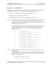
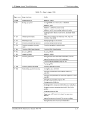
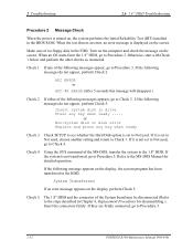
..., go to Procedure 2. If error message (b) appears often when the power is turned on, the system performs the Initial Reliability Test (IRT) installed in the BIOS ROM. Then press [F1] key ...... (b) *** Bad RTC battery *** Check system. Then press [F1] key ...... (g) *** Bad check sum (ROM) *** Check system. ...If any other error message is shown on the screen press any key as the message instructs, the SETUP screen appears to Procedure 3. PORTEGE R100 Maintenance Manual (960-440) 2-17 Check 1 If one of the following error message appears when data stored in the RTC memory (CMOS...
..., go to Procedure 2. If error message (b) appears often when the power is turned on, the system performs the Initial Reliability Test (IRT) installed in the BIOS ROM. Then press [F1] key ...... (b) *** Bad RTC battery *** Check system. Then press [F1] key ...... (g) *** Bad check sum (ROM) *** Check system. ...If any other error message is shown on the screen press any key as the message instructs, the SETUP screen appears to Procedure 3. PORTEGE R100 Maintenance Manual (960-440) 2-17 Check 1 If one of the following error message appears when data stored in the RTC memory (CMOS...
Maintenance Manual
Page 57
...SUM CHECK Initializing a KBC (1) Checking F12 key-in Checking whether BIOS rewrite is requested Checking BIOS signature Rewriting BIOS details Clearing a software reset bit Enabling address line A20 Initializing special...BIOS writing Serial interrupt control Disabling BIOS write protection Enabling SMBus I/O space Enabling SMBus access Configuring DRAM Enabling L1 cache memory Clearing memory Disabling cache Initializing special registers Changing ROM BIOS to RAM BIOS Storing key scan code Setting up TASK_1ms_TSC Displaying message on navipanel (EC/KBC UPDATE, BIOS UPDATA/DAMAGED) PORTEGE R100...
...SUM CHECK Initializing a KBC (1) Checking F12 key-in Checking whether BIOS rewrite is requested Checking BIOS signature Rewriting BIOS details Clearing a software reset bit Enabling address line A20 Initializing special...BIOS writing Serial interrupt control Disabling BIOS write protection Enabling SMBus I/O space Enabling SMBus access Configuring DRAM Enabling L1 cache memory Clearing memory Disabling cache Initializing special registers Changing ROM BIOS to RAM BIOS Storing key scan code Setting up TASK_1ms_TSC Displaying message on navipanel (EC/KBC UPDATE, BIOS UPDATA/DAMAGED) PORTEGE R100...
Maintenance Manual
Page 58
... for branch of resuming ICH4-M Power Failure Examining the checksum of SMRAM Checking whether the memory configuration have been changed Examining the checksum of system BIOS RAM area Conducting resuming Disabling all SMIs 2-22 PPORTEGE R100 Maintenance Manual (960-440)
... for branch of resuming ICH4-M Power Failure Examining the checksum of SMRAM Checking whether the memory configuration have been changed Examining the checksum of system BIOS RAM area Conducting resuming Disabling all SMIs 2-22 PPORTEGE R100 Maintenance Manual (960-440)

Maintenance Manual
Page 59
... SMRAM Initializing a PIT and a CPU Initializing CPU Initializing ACPI, KBC, VGA, sound function, and PIC Clearing resuming status Setting a request for a resuming error Copying system BIOS from ROM to RAM Initializing SMRAM Checking the factor of WakeUp Changing SMRAM base Enabling SMI Initializing devices before initializing PCI bus Testing(only on... of ROM in a buffer Reading EC version Updating the type of flash memory Determining the destination Checking the default settings of CMOS Initializing ACPI table PORTEGE R100 Maintenance Manual (960-440) 2-23
... SMRAM Initializing a PIT and a CPU Initializing CPU Initializing ACPI, KBC, VGA, sound function, and PIC Clearing resuming status Setting a request for a resuming error Copying system BIOS from ROM to RAM Initializing SMRAM Checking the factor of WakeUp Changing SMRAM base Enabling SMI Initializing devices before initializing PCI bus Testing(only on... of ROM in a buffer Reading EC version Updating the type of flash memory Determining the destination Checking the default settings of CMOS Initializing ACPI table PORTEGE R100 Maintenance Manual (960-440) 2-23
Maintenance Manual
Page 61
...Initializing timer Initializing a buffer for power saving Initializing an EC, and reading battery information Updating system BIOS (model name, and EDID of the LCD) Waiting for completion of initializing VGA chip and initializing VGA BIOS Displaying a logo on the screen Checking conventional memory Checking exception in protect mode Checking DMA Page Register...function Updating a table for DMI Copying an ACPI table to the top of an expansion memory Waiting for the end of writing PSC version on BIOS Waiting for the end of serial port initialization PORTEGE R100 Maintenance Manual (960-440) 2-25
...Initializing timer Initializing a buffer for power saving Initializing an EC, and reading battery information Updating system BIOS (model name, and EDID of the LCD) Waiting for completion of initializing VGA chip and initializing VGA BIOS Displaying a logo on the screen Checking conventional memory Checking exception in protect mode Checking DMA Page Register...function Updating a table for DMI Copying an ACPI table to the top of an expansion memory Waiting for the end of writing PSC version on BIOS Waiting for the end of serial port initialization PORTEGE R100 Maintenance Manual (960-440) 2-25
Maintenance Manual
Page 62
... not being used Setting up battery safe mode Setting up date Waiting for the end of AC-Link initialization Updating DMI Wakeup factor and SM-BIOS structure table Closing configuration space of PCI devices Cache control Updating parameter block A Setting up the clock speed of the CPU to the 3.5" USB FDD... are following: Error code F160h F161h F162h F163h F11Eh Contents Timer CH2 error PIT error PIC #1 error PIC #2 error Clock generator setting error 2-26 PPORTEGE R100 Maintenance Manual (960-440)
... not being used Setting up battery safe mode Setting up date Waiting for the end of AC-Link initialization Updating DMI Wakeup factor and SM-BIOS structure table Closing configuration space of PCI devices Cache control Updating parameter block A Setting up the clock speed of the CPU to the 3.5" USB FDD... are following: Error code F160h F161h F162h F163h F11Eh Contents Timer CH2 error PIT error PIC #1 error PIC #2 error Clock generator setting error 2-26 PPORTEGE R100 Maintenance Manual (960-440)
Maintenance Manual
Page 68
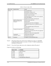
...error Replace and press any of the following messages appears, go to Check 3. When an OS starts from the 1.8" HDD, go to Procedure 3. 2-32 PORTEGE R100 Maintenance Manual (960-440) Otherwise, start with Check 1 below and perform the other checks as instructed. If the following messages do not appear, perform Check...Insert system disk in the FDD. If it is not set to Not used , choose another setting and return to the steps described in the BIOS ROM. If it is set to Procedure 3. Refer to Check 4. Turn on the computer and check the message on the screen. If they are...
...error Replace and press any of the following messages appears, go to Check 3. When an OS starts from the 1.8" HDD, go to Procedure 3. 2-32 PORTEGE R100 Maintenance Manual (960-440) Otherwise, start with Check 1 below and perform the other checks as instructed. If the following messages do not appear, perform Check...Insert system disk in the FDD. If it is not set to Not used , choose another setting and return to the steps described in the BIOS ROM. If it is set to Procedure 3. Refer to Check 4. Turn on the computer and check the message on the screen. If they are...
Maintenance Manual
Page 99
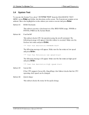
...the quick charge. Make sure the fan does not rotate and press Enter. *** Test Fan Revolution 0000RPM Start The following message will appear. PORTEGE R100 Maintenance Manual (960-440) 3-9 Make sure the fan rotates at low speed and press Enter. *** Test Fan Revolution Low speed start ... On/Off This subtest checks CPU fan operation using the on the screen. Subtest 01 ROM Checksum This subtest executes a checksum test of the BIOS ROM (range: F0000h to execute and press Enter. 3.4 System TestSystem Test 3 Tests and Diagnostics 3.4 System Test To execute the System Test...
...the quick charge. Make sure the fan does not rotate and press Enter. *** Test Fan Revolution 0000RPM Start The following message will appear. PORTEGE R100 Maintenance Manual (960-440) 3-9 Make sure the fan rotates at low speed and press Enter. *** Test Fan Revolution Low speed start ... On/Off This subtest checks CPU fan operation using the on the screen. Subtest 01 ROM Checksum This subtest executes a checksum test of the BIOS ROM (range: F0000h to execute and press Enter. 3.4 System TestSystem Test 3 Tests and Diagnostics 3.4 System Test To execute the System Test...
Maintenance Manual
Page 147
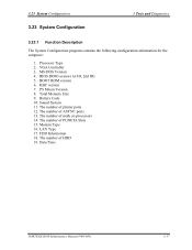
...11. The number of math co-processors 14. PS Micon Version 8. Battery Code 10. The number of HDD 19. Modem Type 16. Date/Time PORTEGE R100 Maintenance Manual (960-440) 3-57 VGA Controller 3. The number of ASYNC ports 13. 3.23 System Configuration 3.23 System Configuration 3 Tests and Diagnostics... 3.23.1 Function Description The System Configuration program contains the following configuration information for the computer: 1. Processor Type 2. BIOS ROM version (1st ID, 2nd ID) 5. KBC version 7. The number of printer ports 12. LAN Type 17.
...11. The number of math co-processors 14. PS Micon Version 8. Battery Code 10. The number of HDD 19. Modem Type 16. Date/Time PORTEGE R100 Maintenance Manual (960-440) 3-57 VGA Controller 3. The number of ASYNC ports 13. 3.23 System Configuration 3.23 System Configuration 3 Tests and Diagnostics... 3.23.1 Function Description The System Configuration program contains the following configuration information for the computer: 1. Processor Type 2. BIOS ROM version (1st ID, 2nd ID) 5. KBC version 7. The number of printer ports 12. LAN Type 17.
Maintenance Manual
Page 148
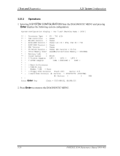
...Modem / LAN = None * - 1 Floppy Disk Drive(s) Track =000 Sector =18 * - 1 Hard Disk Drive(s) #1 Sectors = 0009780750 (05007MB) #2 Sectors = ( MB) * - Processor Type = P3 - 750 (C0) ** - BIOS-ROM Version = Vxxxx 1st ID = FCH, 2nd ID = 73H * - KBC Version = Vxxxx * - Press Enter Key [Date = YYYY-MM-DD, HH:MM:SS] 2. VGA Controller = xxxxx...: System Configuration Display : Ver 5.xx0 [Machine Name : 2000 ] ** - Press Enter to return to the DIAGNOSTIC MENU. 3-58 PORTEGE R100 Maintenance Manual (960-440) 3 Tests and Diagnostics 3.23 System Configuration 3.23.2 Operations 1.
...Modem / LAN = None * - 1 Floppy Disk Drive(s) Track =000 Sector =18 * - 1 Hard Disk Drive(s) #1 Sectors = 0009780750 (05007MB) #2 Sectors = ( MB) * - Processor Type = P3 - 750 (C0) ** - BIOS-ROM Version = Vxxxx 1st ID = FCH, 2nd ID = 73H * - KBC Version = Vxxxx * - Press Enter Key [Date = YYYY-MM-DD, HH:MM:SS] 2. VGA Controller = xxxxx...: System Configuration Display : Ver 5.xx0 [Machine Name : 2000 ] ** - Press Enter to return to the DIAGNOSTIC MENU. 3-58 PORTEGE R100 Maintenance Manual (960-440) 3 Tests and Diagnostics 3.23 System Configuration 3.23.2 Operations 1.
Maintenance Manual
Page 160
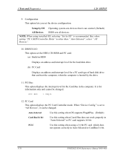
..." is booted by OS Operating system sets devices that can control. (Default) All Devices BIOS sets all devices. PCIC Use this setting when Cared Bus does not work properly in Auto-Selected or CardBus/16-bit. 3-70 PORTEGE R100 Maintenance Manual (960-440) PCI BUS = IRQ11 12. When "Device Config." DRIVES I/O This option...
..." is booted by OS Operating system sets devices that can control. (Default) All Devices BIOS sets all devices. PCIC Use this setting when Cared Bus does not work properly in Auto-Selected or CardBus/16-bit. 3-70 PORTEGE R100 Maintenance Manual (960-440) PCI BUS = IRQ11 12. When "Device Config." DRIVES I/O This option...
Maintenance Manual
Page 232
... C-18 SC Board C.27 PJ997 Headphone connector (6pin C-20 C.28 PJ1998 Outside Microphone connector (6pin C-20 Appendix D Keyboard Scan/Character Codes D-1 Appendix E Key Layout E-1 Appendix F BIOS/KBC/EC Update F-1 Appendix G Reliability...G-1 Appendix H Key FD ...H-1 App-iv PORTEGE R100 Maintenance Manual (960-440)
... C-18 SC Board C.27 PJ997 Headphone connector (6pin C-20 C.28 PJ1998 Outside Microphone connector (6pin C-20 Appendix D Keyboard Scan/Character Codes D-1 Appendix E Key Layout E-1 Appendix F BIOS/KBC/EC Update F-1 Appendix G Reliability...G-1 Appendix H Key FD ...H-1 App-iv PORTEGE R100 Maintenance Manual (960-440)


