
User Manual
Page 16
.... 16 5T80101B [E]p14-18 VHF/UHF OUT PUT VIDEO DIGITAL AUDIO COAXIAL L AUDIO R LINE 1 IN VIDEO L(MONO) AUDIO R 16 To ANALOG AUDIO OUT (white) Audio system (white) Audio cable (not supplied) (red) (red) To audio inputs of MW27F51 INPUT Camcorder (yellow) (white) (red) To AUDIO (L/R)/VIDEO OUT Audio/Video cable (not supplied) To AUDIO (L/R)/VIDEO...
.... 16 5T80101B [E]p14-18 VHF/UHF OUT PUT VIDEO DIGITAL AUDIO COAXIAL L AUDIO R LINE 1 IN VIDEO L(MONO) AUDIO R 16 To ANALOG AUDIO OUT (white) Audio system (white) Audio cable (not supplied) (red) (red) To audio inputs of MW27F51 INPUT Camcorder (yellow) (white) (red) To AUDIO (L/R)/VIDEO OUT Audio/Video cable (not supplied) To AUDIO (L/R)/VIDEO...
Service Manual
Page 48
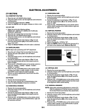
... 4. Activate the adjustment mode display of Fig. 1-1 and press the channel button (08) on the remote control to Fig. 2-2) 2-4: WHITE BALANCE NOTE: Adjust after performing adjustments in Aging Test for more than 15 minutes. 3. SIZE". 4. Using the remote control, set the ...on right and left becomes minimum. 2-10: VERTICAL LINEARITY NOTE: Adjust after performing CUT OFF adjustment. 1. Receive the monoscope pattern. 2. horizontal line Notch Shadow mask Fig. 2-2 2-9: VERTICAL SIZE 1. UP/DOWN button on the remote control to the Right/Left OVER SCAN Quantity. 2-6: HORIZONTAL...
... 4. Activate the adjustment mode display of Fig. 1-1 and press the channel button (08) on the remote control to Fig. 2-2) 2-4: WHITE BALANCE NOTE: Adjust after performing adjustments in Aging Test for more than 15 minutes. 3. SIZE". 4. Using the remote control, set the ...on right and left becomes minimum. 2-10: VERTICAL LINEARITY NOTE: Adjust after performing CUT OFF adjustment. 1. Receive the monoscope pattern. 2. horizontal line Notch Shadow mask Fig. 2-2 2-9: VERTICAL SIZE 1. UP/DOWN button on the remote control to the Right/Left OVER SCAN Quantity. 2-6: HORIZONTAL...

Service Manual
Page 49
... control, set to select "BRI CENT". 9. UP/DOWN button on the remote control until the white 15% is starting to Fig. 2-4). 6. Activate the adjustment mode display of the both ends vertical lines are straight. 2-16: BRIGHT CENTER 1. Press the INPUT button on the remote control to normal .... Press the VOL. Press the DVD button on the remote control to TP806. 4. UP/DOWN button on the remote control until the both ends vertical lines are straight. 2-13: CORNER CORR TOP 1. Receive the monoscope pattern. (RF Input) 2. Activate the adjustment mode display of Fig. 1-1 and 9....
... control, set to select "BRI CENT". 9. UP/DOWN button on the remote control until the white 15% is starting to Fig. 2-4). 6. Activate the adjustment mode display of the both ends vertical lines are straight. 2-16: BRIGHT CENTER 1. Press the INPUT button on the remote control to normal .... Press the VOL. Press the DVD button on the remote control to TP806. 4. UP/DOWN button on the remote control until the both ends vertical lines are straight. 2-13: CORNER CORR TOP 1. Receive the monoscope pattern. (RF Input) 2. Activate the adjustment mode display of Fig. 1-1 and 9....

Service Manual
Page 84
...4545-83 CP1704 A1561WV2-2P TH1701 ZPB45BL3R0A 1 2 6 21 CP1707 003P-2100 1 CP1708 003P-2100 1 AC120V_60Hz CD1702 09415910 BLADE WIDE WHITE BLACK CD1703 WHITE CD1704 F1701 6.3A125V 6.3V125V BLACK 5 L1704 W5T_20X10X10A FH1701 EYF-52BCY FH1702 EYF-52BCY 6.3A 125V 4 R1701 1.5M 1/2W C1701 275V0....33 ECQUL 3 4 1 2 COIL,LINE FILTER L1701_1 SS28V-R22110-CH 17.6 0.4 43 FEED BACK R1707 C1702 IC1701 PS2561AL1-1-V(W) 3 10K ...
...4545-83 CP1704 A1561WV2-2P TH1701 ZPB45BL3R0A 1 2 6 21 CP1707 003P-2100 1 CP1708 003P-2100 1 AC120V_60Hz CD1702 09415910 BLADE WIDE WHITE BLACK CD1703 WHITE CD1704 F1701 6.3A125V 6.3V125V BLACK 5 L1704 W5T_20X10X10A FH1701 EYF-52BCY FH1702 EYF-52BCY 6.3A 125V 4 R1701 1.5M 1/2W C1701 275V0....33 ECQUL 3 4 1 2 COIL,LINE FILTER L1701_1 SS28V-R22110-CH 17.6 0.4 43 FEED BACK R1707 C1702 IC1701 PS2561AL1-1-V(W) 3 10K ...


