
Toshiba Online User's Guide for Satellite A200/A205
Page 31
...Uploading to, and downloading files from, the Internet 131 Exploring audio features 131 Recording sounds 131 Using external speakers or headphones..........132 Web Camera 132 Using PC Cards 133 Inserting a PC Card 133 Removing a PC Card 134 Setting up a PC Card for your computer ... memory media 137 Removing memory media 137 Using the i.LINK® port 138 Chapter 5: Toshiba Utilities 139 TOSHIBA Assist 140 Connect 141 Secure 142 Protect & Fix 143 Optimize 144 Toshiba Application Installer 145 Setting passwords 146 Using an instant password 146 Using a supervisor password 147
...Uploading to, and downloading files from, the Internet 131 Exploring audio features 131 Recording sounds 131 Using external speakers or headphones..........132 Web Camera 132 Using PC Cards 133 Inserting a PC Card 133 Removing a PC Card 134 Setting up a PC Card for your computer ... memory media 137 Removing memory media 137 Using the i.LINK® port 138 Chapter 5: Toshiba Utilities 139 TOSHIBA Assist 140 Connect 141 Secure 142 Protect & Fix 143 Optimize 144 Toshiba Application Installer 145 Setting passwords 146 Using an instant password 146 Using a supervisor password 147
Toshiba Online User's Guide for Satellite A200/A205
Page 96
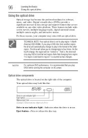
... regions four times. Eject button-Press to region 1 is recommended that last region. These features include widescreen movies, multiple language tracks, digital surround sound, multiple camera angles, and interactive menus. Digital versatile discs (DVDs) provide a significant increase in use indicator light-Indicates when the drive is in data storage and support...
... regions four times. Eject button-Press to region 1 is recommended that last region. These features include widescreen movies, multiple language tracks, digital surround sound, multiple camera angles, and interactive menus. Digital versatile discs (DVDs) provide a significant increase in use indicator light-Indicates when the drive is in data storage and support...
Toshiba Online User's Guide for Satellite A200/A205
Page 132
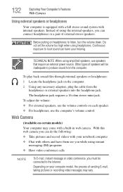
...use speakers that require an external power source. Depending on certain models) Your computer may vary. 132 Exploring Your Computer's Features Web Camera Using external speakers or headphones Your computer is equipped with a full stereo sound system with others and have them see you while ...be connected to the Internet. Instead of using the internal speakers, you can connect headphones or a pair of external stereo speakers. Web Camera (Available on your notebook computer ❖ Chat with internal speakers. TECHNICAL NOTE: When using headphones. Do not set the volume too ...
...use speakers that require an external power source. Depending on certain models) Your computer may vary. 132 Exploring Your Computer's Features Web Camera Using external speakers or headphones Your computer is equipped with a full stereo sound system with others and have them see you while ...be connected to the Internet. Instead of using the internal speakers, you can connect headphones or a pair of external stereo speakers. Web Camera (Available on your notebook computer ❖ Chat with internal speakers. TECHNICAL NOTE: When using headphones. Do not set the volume too ...
Toshiba Online User's Guide for Satellite A200/A205
Page 136
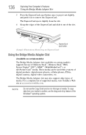
... for this type of media. These media can be used with a variety of supported media, visit Toshiba's Web site at accessories.toshiba.com. For a complete list of digital products: digital music players, cellular phones, PDAs, digital cameras, digital video camcorders, etc. To copy data from the slot. 4 Grasp the edges of the ExpressCard...
... for this type of media. These media can be used with a variety of supported media, visit Toshiba's Web site at accessories.toshiba.com. For a complete list of digital products: digital music players, cellular phones, PDAs, digital cameras, digital video camcorders, etc. To copy data from the slot. 4 Grasp the edges of the ExpressCard...
Maintenance Manual
Page 6
... card Troubleshooting 2-32 2.13 IEEE 1394 Troubleshooting 2-34 2.14 Wireless LAN Troubleshooting 2-36 2.15 Camera Troubleshooting 2-38 2.16 Bluetooth Troubleshooting 2-40 2.17 4 in 1 card Troubleshooting 2-42 2.18 1st HDD Troubleshooting 2-44 2.19 2nd HDD Troubleshooting 2-46 vi [CONFIDENTIAL] Satellite A200 Series Maintenance Manual Table of Contents Chapter 1 Hardware Overview 1.1 Features ...1-1 1.2 System Unit...
... card Troubleshooting 2-32 2.13 IEEE 1394 Troubleshooting 2-34 2.14 Wireless LAN Troubleshooting 2-36 2.15 Camera Troubleshooting 2-38 2.16 Bluetooth Troubleshooting 2-40 2.17 4 in 1 card Troubleshooting 2-42 2.18 1st HDD Troubleshooting 2-44 2.19 2nd HDD Troubleshooting 2-46 vi [CONFIDENTIAL] Satellite A200 Series Maintenance Manual Table of Contents Chapter 1 Hardware Overview 1.1 Features ...1-1 1.2 System Unit...
Maintenance Manual
Page 8
4.4 Memory Card 4.5 HDD 4.6 Expansion Memory 4.7 Optical Drive Module 4.8 Optical Drive 4.9 Keyboard 4.10 Display Assembly 4.11 Display Mask 4.12 FL Inverter Board 4.13 LCD Module 4.14 WLAN antennas 4.15 Camera and Microphone 4.16 Bluetooth module viii [CONFIDENTIAL] Satellite A200 Series Maintenance Manual
4.4 Memory Card 4.5 HDD 4.6 Expansion Memory 4.7 Optical Drive Module 4.8 Optical Drive 4.9 Keyboard 4.10 Display Assembly 4.11 Display Mask 4.12 FL Inverter Board 4.13 LCD Module 4.14 WLAN antennas 4.15 Camera and Microphone 4.16 Bluetooth module viii [CONFIDENTIAL] Satellite A200 Series Maintenance Manual
Maintenance Manual
Page 17
...; Kensington lock • One IEEE 1394a port • Fingerprint authentication • One 4-in-1 push-push type flash card connector and card reader • Built-in camera with microphone • One type II PCMCIA slot with shutter door • One SIM card reader ‰ Express Card Slot • TI 8402 card bus...
...; Kensington lock • One IEEE 1394a port • Fingerprint authentication • One 4-in-1 push-push type flash card connector and card reader • Built-in camera with microphone • One type II PCMCIA slot with shutter door • One SIM card reader ‰ Express Card Slot • TI 8402 card bus...
Maintenance Manual
Page 18
Bluetooth is a short-range wireless technology used to create PANs (Personal Area Networks) among your devices, as well as cell phones and digital cameras. ‰ OS • Windows Vista Home Basic/ Home Premium (32/64 bit support) • Windows Vista Business (32/64 support) • Vista Premium Logo 1-4 Minnesota ...
Bluetooth is a short-range wireless technology used to create PANs (Personal Area Networks) among your devices, as well as cell phones and digital cameras. ‰ OS • Windows Vista Home Basic/ Home Premium (32/64 bit support) • Windows Vista Business (32/64 support) • Vista Premium Logo 1-4 Minnesota ...
Maintenance Manual
Page 31
... Troubleshooting 27 2.11 Modem Troubleshooting 30 2.12 Express card Troubleshooting 32 2.13 IEEE 1394 Troubleshooting 34 2.14 Wireless LAN Troubleshooting 36 2.15 Camera Troubleshooting 38 2.16 Bluetooth Troubleshooting 40 2.17 4 in 1 card Troubleshooting 42 2.18 1st HDD Troubleshooting 44 2.19 2nd HDD Troubleshooting 47 Satellite A200/A205/Pro A200 Series Maintenance Manual 1 [CONFIDENTIAL]
... Troubleshooting 27 2.11 Modem Troubleshooting 30 2.12 Express card Troubleshooting 32 2.13 IEEE 1394 Troubleshooting 34 2.14 Wireless LAN Troubleshooting 36 2.15 Camera Troubleshooting 38 2.16 Bluetooth Troubleshooting 40 2.17 4 in 1 card Troubleshooting 42 2.18 1st HDD Troubleshooting 44 2.19 2nd HDD Troubleshooting 47 Satellite A200/A205/Pro A200 Series Maintenance Manual 1 [CONFIDENTIAL]
Maintenance Manual
Page 32
... 25 Optical drive troubleshooting process 27 Modem troubleshooting process 30 Express card troubleshooting process 32 IEEE 1394 troubleshooting process 34 Wireless LAN troubleshooting process 36 Camera troubleshooting process 38 Bluetooth troubleshooting process 40 4 in 1 card troubleshooting process 42 1st HDD troubleshooting process 44 2nd HDD troubleshooting process 45 Tables Table 2-1 Battery...
... 25 Optical drive troubleshooting process 27 Modem troubleshooting process 30 Express card troubleshooting process 32 IEEE 1394 troubleshooting process 34 Wireless LAN troubleshooting process 36 Camera troubleshooting process 38 Bluetooth troubleshooting process 40 4 in 1 card troubleshooting process 42 1st HDD troubleshooting process 44 2nd HDD troubleshooting process 45 Tables Table 2-1 Battery...
Maintenance Manual
Page 33
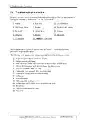
... ports for CPU door) 4. 2DD or 2HD formatted work disk for floppy disk drive troubleshooting 7. Sycard (EXPRESS CARD test card) 6. Music CD Satellite A200/A205/Pro A200 Series Maintenance Manual [CONFIDENTIAL] 3 Camera 4. Keyboard 8. The following tools are : 1. Multimeter 9. External monitor 10. USB Floppy Drive 7. Speaker 12. Modem 14. Multimedia sound system with line...
... ports for CPU door) 4. 2DD or 2HD formatted work disk for floppy disk drive troubleshooting 7. Sycard (EXPRESS CARD test card) 6. Music CD Satellite A200/A205/Pro A200 Series Maintenance Manual [CONFIDENTIAL] 3 Camera 4. Keyboard 8. The following tools are : 1. Multimeter 9. External monitor 10. USB Floppy Drive 7. Speaker 12. Modem 14. Multimedia sound system with line...
Maintenance Manual
Page 69
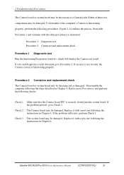
... FFC is functioning properly, perform the following checks. Replace it with the other procedures as instructed. Either of a Camera fault. Figure 2-14 outlines the process. Satellite A200/A205/Pro A200 Series Maintenance Manual [CONFIDENTIAL] 39 Procedure 1: Diagnostic test Procedure 2: Connector and replacement check Procedure 1 Diagnostic test Run the functioning Program in Chapter 4. Check...
... FFC is functioning properly, perform the following checks. Replace it with the other procedures as instructed. Either of a Camera fault. Figure 2-14 outlines the process. Satellite A200/A205/Pro A200 Series Maintenance Manual [CONFIDENTIAL] 39 Procedure 1: Diagnostic test Procedure 2: Connector and replacement check Procedure 1 Diagnostic test Run the functioning Program in Chapter 4. Check...
Maintenance Manual
Page 115
......4-23 4.9 Keyboard ...4-25 4.10 Display Assembly 4-28 4.11 Display Mask ...4-33 4.12 FL Inverter Board 4-35 4.13 LCD Module ...4-37 4.14 WLAN antennas 4-40 4.15 Camera and Microphone 4-41 4.16 Bluetooth module 4-43 4.17 Touch Pad...4-45 4.18 Fingerprint Module 4-47 4.19 Speakers ...4-49 4.20 Function Button Board 4-51 4.21 USB... Board ...4-53 4.22 MDC Card...4-55 4.23 Wireless Module 4-57 4.24 System Fan ...4-58 4.25 System Board ...4-60 4.26 VGA Board ...4-63 4.27 CPU ...4-66 Minnesota 10M/10MG Series Maintenance Manual 4-i
......4-23 4.9 Keyboard ...4-25 4.10 Display Assembly 4-28 4.11 Display Mask ...4-33 4.12 FL Inverter Board 4-35 4.13 LCD Module ...4-37 4.14 WLAN antennas 4-40 4.15 Camera and Microphone 4-41 4.16 Bluetooth module 4-43 4.17 Touch Pad...4-45 4.18 Fingerprint Module 4-47 4.19 Speakers ...4-49 4.20 Function Button Board 4-51 4.21 USB... Board ...4-53 4.22 MDC Card...4-55 4.23 Wireless Module 4-57 4.24 System Fan ...4-58 4.25 System Board ...4-60 4.26 VGA Board ...4-63 4.27 CPU ...4-66 Minnesota 10M/10MG Series Maintenance Manual 4-i
Maintenance Manual
Page 117
...Figure 4-56 Figure 4-57 Figure 4-58 Figure 4-59 Figure 4-60 Figure 4-61 Figure 4-62 Figure 4-63 Figure 4-64 Figure 4-65 Figure 4-66 Removing CRT module screws and display assembly 4-30 Removing the display assembly 4-31 Removing the rubber pads 4-33 Removing the display mask screws 4-33 ... LCD Module 4-38 Removing the bracket screws 4-38 Removing the LVDS cable 4-39 Removing the WLAN antennas 4-40 Removing the CMOS cable & camera 4-41 Removing the microphone 4-41 Disconnecting the Bluetooth cable 4-43 Removing the Bluetooth module 4-43 Removing the touch pad cable 4-45 Removing the...
...Figure 4-56 Figure 4-57 Figure 4-58 Figure 4-59 Figure 4-60 Figure 4-61 Figure 4-62 Figure 4-63 Figure 4-64 Figure 4-65 Figure 4-66 Removing CRT module screws and display assembly 4-30 Removing the display assembly 4-31 Removing the rubber pads 4-33 Removing the display mask screws 4-33 ... LCD Module 4-38 Removing the bracket screws 4-38 Removing the LVDS cable 4-39 Removing the WLAN antennas 4-40 Removing the CMOS cable & camera 4-41 Removing the microphone 4-41 Disconnecting the Bluetooth cable 4-43 Removing the Bluetooth module 4-43 Removing the touch pad cable 4-45 Removing the...
Maintenance Manual
Page 119
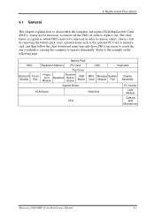
... Function Speakers Button Board USB Board MDC Wireless System Card Module Fan Display Assembly System Board FL Inverter VGA Board Heat Sink LCD Module CPU Camera and Microphone Minnesota 10M/10MG Series Maintenance Manual 4-1 4 Replacement Procedures 4.1 General This chapter explains how to the example on the following page. The chart below...
... Function Speakers Button Board USB Board MDC Wireless System Card Module Fan Display Assembly System Board FL Inverter VGA Board Heat Sink LCD Module CPU Camera and Microphone Minnesota 10M/10MG Series Maintenance Manual 4-1 4 Replacement Procedures 4.1 General This chapter explains how to the example on the following page. The chart below...
Maintenance Manual
Page 120
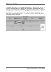
... Function Speakers Button Board USB Board MDC Wireless System Card Module Fan Display Assembly System Board FL Inverter VGA Board Heat Sink LCD Module CPU Camera and Microphone 4-2 Minnesota 10M/10MG Series Maintenance Manual The keyboard must be removed before the CPU can be removed.
... Function Speakers Button Board USB Board MDC Wireless System Card Module Fan Display Assembly System Board FL Inverter VGA Board Heat Sink LCD Module CPU Camera and Microphone 4-2 Minnesota 10M/10MG Series Maintenance Manual The keyboard must be removed before the CPU can be removed.
Maintenance Manual
Page 147
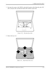
Figure 4-30 Disconnecting cables 4. 4 Replacement Procedures 3. Figure 4-31 Removing the top cover Minnesota 10M/10MG Series Maintenance Manual 4-29 Remove the top cover. Disconnect the camera cable (CMOS), right and left speaker cables, Bluetooth cable, FPC cable, touch pad cable, and function button cable from the system board.
Figure 4-30 Disconnecting cables 4. 4 Replacement Procedures 3. Figure 4-31 Removing the top cover Minnesota 10M/10MG Series Maintenance Manual 4-29 Remove the top cover. Disconnect the camera cable (CMOS), right and left speaker cables, Bluetooth cable, FPC cable, touch pad cable, and function button cable from the system board.
Maintenance Manual
Page 150
.... 7. Replace the top cover. 6. Secure the top cover with four M2.5x8 screws. 8. Reinstall the keyboard. 4-32 Minnesota 10M/10MG Series Maintenance Manual Connect the camera cable (CMOS), right and left speaker cables, Bluetooth cable, FPC cable, touch pad cable, and function button cable to the system board. 5. Feed the CMOS...
.... 7. Replace the top cover. 6. Secure the top cover with four M2.5x8 screws. 8. Reinstall the keyboard. 4-32 Minnesota 10M/10MG Series Maintenance Manual Connect the camera cable (CMOS), right and left speaker cables, Bluetooth cable, FPC cable, touch pad cable, and function button cable to the system board. 5. Feed the CMOS...
Maintenance Manual
Page 159
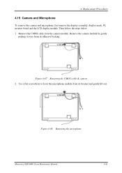
Remove the camera module by gently peeling it away from its bracket and gently lift out. Remove the CMOS cable from its adhesive backing. Figure 4-48 Removing the microphone Minnesota 10M/10MG Series Maintenance Manual 4-41 Use a flat screwdriver to lever the microphone module from the camera module. 4 Replacement Procedures 4.15 Camera and Microphone To remove the camera and microphone, first remove the display assembly, display mask, FL inverter board and the LCD display module. Figure 4-47 Removing the CMOS cable & camera 2. Then follow the steps below. 1.
Remove the camera module by gently peeling it away from its bracket and gently lift out. Remove the CMOS cable from its adhesive backing. Figure 4-48 Removing the microphone Minnesota 10M/10MG Series Maintenance Manual 4-41 Use a flat screwdriver to lever the microphone module from the camera module. 4 Replacement Procedures 4.15 Camera and Microphone To remove the camera and microphone, first remove the display assembly, display mask, FL inverter board and the LCD display module. Figure 4-47 Removing the CMOS cable & camera 2. Then follow the steps below. 1.
Maintenance Manual
Page 160
4 Replacement Procedures Installing the Camera and Microphone To install the camera and microphone, follow the steps below and refer to the adhesive backing at the top of the display mask. 2. Fix the camera module to the figures in its respective bracket. 4-42 Minnesota 10M/10MG Series Maintenance Manual Connect the CMOS cable to the camera module. 3. Push the microphone into place in the preceding sections. 1.
4 Replacement Procedures Installing the Camera and Microphone To install the camera and microphone, follow the steps below and refer to the adhesive backing at the top of the display mask. 2. Fix the camera module to the figures in its respective bracket. 4-42 Minnesota 10M/10MG Series Maintenance Manual Connect the CMOS cable to the camera module. 3. Push the microphone into place in the preceding sections. 1.


