Toshiba Online Users Guide for Satellite A100/A105
Page 1
Satellite® A100/A105 User's Guide If you need assistance: ❖ Toshiba's Support Web site pcsupport.toshiba.com ❖ Toshiba Global Support Centre Calling within the United States (800) 457-7777 Calling from outside the United States (949) 859-4273 For more information, see "If Something Goes Wrong" on page 172 in this guide. PMAD00063010 11/05
Satellite® A100/A105 User's Guide If you need assistance: ❖ Toshiba's Support Web site pcsupport.toshiba.com ❖ Toshiba Global Support Centre Calling within the United States (800) 457-7777 Calling from outside the United States (949) 859-4273 For more information, see "If Something Goes Wrong" on page 172 in this guide. PMAD00063010 11/05
Toshiba Online Users Guide for Satellite A100/A105
Page 7
... and may interfere with and/or damage this device. If you use due to its operation in the United States for harmful interference to co-channel Mobile Satellite systems. High power radars are designed to be interoperable with any wireless LAN product that the sum of.... The termination on Web site http://www.toshibaeurope.com/computers/tnt/bluetooth.htm in Europe or pcsupport.toshiba.com in the 5.15 GHz to a telephone interface. Wireless Interoperability The TOSHIBA Wireless LAN Mini PCI Card products are allocated as defined by the Institute of Electrical and Electronics Engineers...
... and may interfere with and/or damage this device. If you use due to its operation in the United States for harmful interference to co-channel Mobile Satellite systems. High power radars are designed to be interoperable with any wireless LAN product that the sum of.... The termination on Web site http://www.toshibaeurope.com/computers/tnt/bluetooth.htm in Europe or pcsupport.toshiba.com in the 5.15 GHz to a telephone interface. Wireless Interoperability The TOSHIBA Wireless LAN Mini PCI Card products are allocated as defined by the Institute of Electrical and Electronics Engineers...
Toshiba Online Users Guide for Satellite A100/A105
Page 25
... and logos are registered trademarks of Toshiba Corporation. and/or Toshiba Corporation. Manufactured by Toshiba under license. TouchPad is a trademark of Toshiba America Information Systems, Inc. For disposal, reuse or recycling information, please contact your local government or the Electronic Industries Alliance at www.eiae.org. 25 Trademarks Satellite is a registered trademark of Synaptics, Inc...
... and logos are registered trademarks of Toshiba Corporation. and/or Toshiba Corporation. Manufactured by Toshiba under license. TouchPad is a trademark of Toshiba America Information Systems, Inc. For disposal, reuse or recycling information, please contact your local government or the Electronic Industries Alliance at www.eiae.org. 25 Trademarks Satellite is a registered trademark of Synaptics, Inc...
Maintenance Manual
Page 4
The procedures described in this manual are intended to help service technicians isolate faulty Field Replaceable Units (FRUs) and replace them in bodily injury, if the safety instruction is not observed. Each of a hazard that could result in death... of a hazard that could cause overheating, smoke or fire. ? iv Satellite A100/A105 / TECRA A7 Maintenance Manual Be sure to explode. Preface This maintenance manual describes how to perform hardware service maintenance for the Toshiba Personal Computer Satellite A100/A105 / TECRA A7, referred to as shown below. If you replace the ...
The procedures described in this manual are intended to help service technicians isolate faulty Field Replaceable Units (FRUs) and replace them in bodily injury, if the safety instruction is not observed. Each of a hazard that could result in death... of a hazard that could cause overheating, smoke or fire. ? iv Satellite A100/A105 / TECRA A7 Maintenance Manual Be sure to explode. Preface This maintenance manual describes how to perform hardware service maintenance for the Toshiba Personal Computer Satellite A100/A105 / TECRA A7, referred to as shown below. If you replace the ...

Maintenance Manual
Page 5
... into the following : ? Handling the LCD module ? Keyboard scan/character codes ? BIOS Rewrite Procedures Satellite A100/A105 / TECRA A7 Maintenance Manual v Appendices The appendices describe the following parts: Chapter 1 Hardware Overview describes the Satellite A100/A105 / TECRA A7 system unit and each FRU. Key layout ? Board layout ? Chapter 4 Replacement Procedures describes the removal and replacement...
... into the following : ? Handling the LCD module ? Keyboard scan/character codes ? BIOS Rewrite Procedures Satellite A100/A105 / TECRA A7 Maintenance Manual v Appendices The appendices describe the following parts: Chapter 1 Hardware Overview describes the Satellite A100/A105 / TECRA A7 system unit and each FRU. Key layout ? Board layout ? Chapter 4 Replacement Procedures describes the removal and replacement...
Maintenance Manual
Page 7
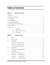
Table of Contents Chapter 1 Hardware Overview 1.1 Features...1 1.2 System Unit Components...9 1.3 2.5-inch HDD...15 1.4 DVD-ROM Drive...16 1.5 CD-RW/DVD-ROM Drive 17 1.6 DVD Super Multi (+-R Double Layer 18 1.7 Power Supply ...19 1.8 Batteries ...20 1.1.1 ... Board...2-9 Procedure 3 Replacement Check 2-10 2.5 2.5-inch HDD ...2-11 Procedure 1 Message Check 2-11 Procedure 2 Partition Check 2-11 Procedure 3 Format Check 2-12 Procedure 4 Test Program Check 2-13 Satellite A100/A105 / TECRA A7 Maintenance Manual vii
Table of Contents Chapter 1 Hardware Overview 1.1 Features...1 1.2 System Unit Components...9 1.3 2.5-inch HDD...15 1.4 DVD-ROM Drive...16 1.5 CD-RW/DVD-ROM Drive 17 1.6 DVD Super Multi (+-R Double Layer 18 1.7 Power Supply ...19 1.8 Batteries ...20 1.1.1 ... Board...2-9 Procedure 3 Replacement Check 2-10 2.5 2.5-inch HDD ...2-11 Procedure 1 Message Check 2-11 Procedure 2 Partition Check 2-11 Procedure 3 Format Check 2-12 Procedure 4 Test Program Check 2-13 Satellite A100/A105 / TECRA A7 Maintenance Manual vii
Maintenance Manual
Page 17
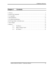
1 Hardware Overview Chapter 1 Contents 1.1 Features...1 1.2 System Unit Components...9 1.3 2.5-inch HDD...15 1.4 DVD-ROM Drive...16 1.5 CD-RW/DVD-ROM Drive 17 1.6 DVD Super Multi (+-R Double Layer 18 1.7 Power Supply ...19 1.8 Batteries ...20 1.1.1 Main Battery 20 1.1.2 Battery Charging Control 20 1.1.3 RTC Battery 21 Satellite A100/A105 / TECRA A7 Maintenance Manual iii
1 Hardware Overview Chapter 1 Contents 1.1 Features...1 1.2 System Unit Components...9 1.3 2.5-inch HDD...15 1.4 DVD-ROM Drive...16 1.5 CD-RW/DVD-ROM Drive 17 1.6 DVD Super Multi (+-R Double Layer 18 1.7 Power Supply ...19 1.8 Batteries ...20 1.1.1 Main Battery 20 1.1.2 Battery Charging Control 20 1.1.3 RTC Battery 21 Satellite A100/A105 / TECRA A7 Maintenance Manual iii

Maintenance Manual
Page 18
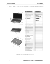
1 Hardware Overview Figures Figure 1- 1 id Parts description placement 6 Figure 1- 2 The computer Block diagram 7 Figure 1- 3 System Board configuration 8 Figure 1- 4 System unit block diagram 9 Figure 1- 5 2.5-inch HDD...15 Figure 1- 6 DVD-ROM drive 16 Tables Table 1- 1 2.5-inch HDD specifications 15 Table 1- 2 DVD-ROM drive specifications 16 Table 1- 3 ...-ROM drive specifications 17 Table 1- 4 DVD Super Multi drive (+-R Double Layer) specifications 18 Table 1- 5 Battery specifications 20 Table 1-6 Quick/normal charging time 21 iv Satellite A100/A105 / TECRA A7 Maintenance Manual
1 Hardware Overview Figures Figure 1- 1 id Parts description placement 6 Figure 1- 2 The computer Block diagram 7 Figure 1- 3 System Board configuration 8 Figure 1- 4 System unit block diagram 9 Figure 1- 5 2.5-inch HDD...15 Figure 1- 6 DVD-ROM drive 16 Tables Table 1- 1 2.5-inch HDD specifications 15 Table 1- 2 DVD-ROM drive specifications 16 Table 1- 3 ...-ROM drive specifications 17 Table 1- 4 DVD Super Multi drive (+-R Double Layer) specifications 18 Table 1- 5 Battery specifications 20 Table 1-6 Quick/normal charging time 21 iv Satellite A100/A105 / TECRA A7 Maintenance Manual
Maintenance Manual
Page 24
Figure 1- 1 id Parts description placement 6 Satellite A100/A105 / TECRA A7 Maintenance Manual Figures 1-1/1-2/1-3 and 1-4 show the computer and its system unit configuration, respectively. 1 Hardware Overview 1.1 Features ?
Figure 1- 1 id Parts description placement 6 Satellite A100/A105 / TECRA A7 Maintenance Manual Figures 1-1/1-2/1-3 and 1-4 show the computer and its system unit configuration, respectively. 1 Hardware Overview 1.1 Features ?
Maintenance Manual
Page 28
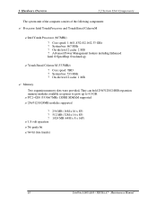
... TBD ? No parity bit ?64-bit data transfer 10 Satellite A100/A105 / TECRA A7 Maintenance Manual System bus: 667 MHz ? ...32M x 16 x 8P) 1024 MB (64M x 8 x 16P) ? Intel Yonah Processor (667MHz) ? Core speed: 1.66/1.83/2.0/2.16/2.33 GHz ? Advanced Power Management features including Enhanced Intel ® SpeedStep ® technology ?Yonah Based Celeron-M (533MHz) ? On-die level 2 cache 1 MB... Yonah Processor and Yonah Based Celeron M ? System bus: 533 MHz ? 1 Hardware Overview 1.2 System Unit Components The system unit of the computer consists of the following components: ?
... TBD ? No parity bit ?64-bit data transfer 10 Satellite A100/A105 / TECRA A7 Maintenance Manual System bus: 667 MHz ? ...32M x 16 x 8P) 1024 MB (64M x 8 x 16P) ? Intel Yonah Processor (667MHz) ? Core speed: 1.66/1.83/2.0/2.16/2.33 GHz ? Advanced Power Management features including Enhanced Intel ® SpeedStep ® technology ?Yonah Based Celeron-M (533MHz) ? On-die level 2 cache 1 MB... Yonah Processor and Yonah Based Celeron M ? System bus: 533 MHz ? 1 Hardware Overview 1.2 System Unit Components The system unit of the computer consists of the following components: ?

Maintenance Manual
Page 30
... detection pins each supports up to 4 jacks can be detected. ? Integrates digital BEEP generator. ? Analog : 5.0V ?48-ping LQFP package. 12 Satellite A100/A105 / TECRA A7 Maintenance Manual Universal Serial Bus (USB) Controller ? RTC ? System Management Bus (SMBus 2.0) ? IEEE 1394 Controller ? Advanced Programmable Interrupt Controller...-D),LINE2(port-E)and MIC2(port-F) are stereo input and output re-tasking. ? 1 Hardware Overview 1.2 System Unit Components ? Power support : Digital : 3.3V ; Supports analog PCBEEP input. ? Low Pin Count (LPC) Interface ?
... detection pins each supports up to 4 jacks can be detected. ? Integrates digital BEEP generator. ? Analog : 5.0V ?48-ping LQFP package. 12 Satellite A100/A105 / TECRA A7 Maintenance Manual Universal Serial Bus (USB) Controller ? RTC ? System Management Bus (SMBus 2.0) ? IEEE 1394 Controller ? Advanced Programmable Interrupt Controller...-D),LINE2(port-E)and MIC2(port-F) are stereo input and output re-tasking. ? 1 Hardware Overview 1.2 System Unit Components ? Power support : Digital : 3.3V ; Supports analog PCBEEP input. ? Low Pin Count (LPC) Interface ?
Maintenance Manual
Page 31
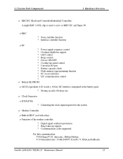
...: For data communication: V.90(China)/V.92 data rates: 28kbps/56kbps V.34 Extended rates: 33.6K/2400/V.32 turbo, V.32bits,and fallbacks Satellite A100/A105 / TECRA A7 Maintenance Manual 13 KBC ? Cooling fan speed control ? Battery EE PROM ? 24C02 equivalent (128 words x 16 bits, I2C... function ? Clock Generator ? Power supply sequence control ? Battery capacity check ? Functions of battery use ? I2C communication control ? ? 1.2 System Unit Components 1 Hardware Overview ? Scan controller function ? Universal I/O port ? Modem Controller ?Built-in the battery pack ?
...: For data communication: V.90(China)/V.92 data rates: 28kbps/56kbps V.34 Extended rates: 33.6K/2400/V.32 turbo, V.32bits,and fallbacks Satellite A100/A105 / TECRA A7 Maintenance Manual 13 KBC ? Cooling fan speed control ? Battery EE PROM ? 24C02 equivalent (128 words x 16 bits, I2C... function ? Clock Generator ? Power supply sequence control ? Battery capacity check ? Functions of battery use ? I2C communication control ? ? 1.2 System Unit Components 1 Hardware Overview ? Scan controller function ? Universal I/O port ? Modem Controller ?Built-in the battery pack ?
Maintenance Manual
Page 32
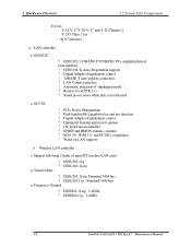
... ? Frequency Channel ? Optimized transmit and receive queues ? Support following 2 kinds of "unplugged mode" ? IEEE802.11g: 2.4GHz 14 Satellite A100/A105 / TECRA A7 Maintenance Manual AC97 interface ? On-board microcontroller ? IEEE802.11a/g: 5.4GHz ? IEEE 802.3u Auto-Negotiation support ?... ? Digital Adaptive Equalization control ? 10BASE-T auto-polarity correction ? PCIe Power Management ? IEEE 802.11g ? 1 Hardware Overview 1.2 System Unit Components For fax: V.34,V.17,V.29 V.27 and V.21 Channel 2 V.253 Class 1 fax - LAN controller ? 82562GZ ? Peak bandwidth...
... ? Frequency Channel ? Optimized transmit and receive queues ? Support following 2 kinds of "unplugged mode" ? IEEE802.11g: 2.4GHz 14 Satellite A100/A105 / TECRA A7 Maintenance Manual AC97 interface ? On-board microcontroller ? IEEE802.11a/g: 5.4GHz ? IEEE 802.3u Auto-Negotiation support ?... ? Digital Adaptive Equalization control ? 10BASE-T auto-polarity correction ? PCIe Power Management ? IEEE 802.11g ? 1 Hardware Overview 1.2 System Unit Components For fax: V.34,V.17,V.29 V.27 and V.21 Channel 2 V.253 Class 1 fax - LAN controller ? 82562GZ ? Peak bandwidth...
Maintenance Manual
Page 37
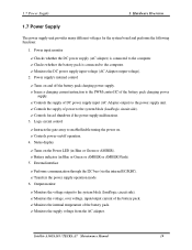
1.7 Power Supply 1 Hardware Overview 1.7 Power Supply The power supply unit provides many different voltages for the system board and performs the following functions: 1. Checks whether the DC power supply (AC adapter) is ... 6. Monitors the supply voltage from the AC adapter. Logic circuit control ? Performs communication through the I2C bus (via the internal EC/KBC). ? Satellite A100/A105 / TECRA A7 Maintenance Manual 19 Instructs the gate array to the power supply unit. ? Output monitor ? Turns on and off operation. 4. Status display ? Power input monitor ?
1.7 Power Supply 1 Hardware Overview 1.7 Power Supply The power supply unit provides many different voltages for the system board and performs the following functions: 1. Checks whether the DC power supply (AC adapter) is ... 6. Monitors the supply voltage from the AC adapter. Logic circuit control ? Performs communication through the I2C bus (via the internal EC/KBC). ? Satellite A100/A105 / TECRA A7 Maintenance Manual 19 Instructs the gate array to the power supply unit. ? Output monitor ? Turns on and off operation. 4. Status display ? Power input monitor ?
Maintenance Manual
Page 44
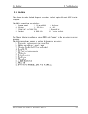
... Chapter 3 for field replaceable units (FRUs) in the computer. Bootable CD 5. Headphone 9. System board 2. 2.5-inch HDD 4. Finger Print 10. Phillips screwdrivers (2 mm, 2.5 mm) 3. Display 5. Microphone 10. The FRUs covered here are required to perform the diagnostic procedures: 1. PC Card loopback connector 6. DVD TSD-1 (TOSHIBA EMI DVD Test Media) Satellite A100/A105 / TECRA A7 Maintenance...
... Chapter 3 for field replaceable units (FRUs) in the computer. Bootable CD 5. Headphone 9. System board 2. 2.5-inch HDD 4. Finger Print 10. Phillips screwdrivers (2 mm, 2.5 mm) 3. Display 5. Microphone 10. The FRUs covered here are required to perform the diagnostic procedures: 1. PC Card loopback connector 6. DVD TSD-1 (TOSHIBA EMI DVD Test Media) Satellite A100/A105 / TECRA A7 Maintenance...

Maintenance Manual
Page 61
The computer automatically detects the external monitor even if resume mode is still an error, perform Check 3. 2-18 Satellite A100/A105 / TECRA A7 Maintenance Manual If an error is detected in Chapter 4, then perform the following cables have the same problem as instructed....off, reconnect it with a new one and return to perform the test. If there is enabled. Procedure 3 Connector Check and Replacement Check The display unit has an LCD module, Fluorescent lamp (FL), panel close switch may be defective. Go to Procedure 2. Go to Procedure 3. Procedure 2 Test Program ...
The computer automatically detects the external monitor even if resume mode is still an error, perform Check 3. 2-18 Satellite A100/A105 / TECRA A7 Maintenance Manual If an error is detected in Chapter 4, then perform the following cables have the same problem as instructed....off, reconnect it with a new one and return to perform the test. If there is enabled. Procedure 3 Connector Check and Replacement Check The display unit has an LCD module, Fluorescent lamp (FL), panel close switch may be defective. Go to Procedure 2. Go to Procedure 3. Procedure 2 Test Program ...

Maintenance Manual
Page 78
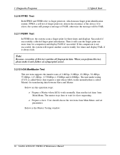
...floppy diskette with more then 50KB spare space in the drive, system will save all log files in the root directory of RAM disk. 2 Satellite A100/A105 / TECRA A7 Maintenance Manual The test items could be selected from the DIAGNOSTIC TEST menu. Loop back connector of the result log file. ...otherwise, system will automatically select the location of LPT ? Note: When booting up the unit for the first time, the system will save all the test ...
...floppy diskette with more then 50KB spare space in the drive, system will save all log files in the root directory of RAM disk. 2 Satellite A100/A105 / TECRA A7 Maintenance Manual The test items could be selected from the DIAGNOSTIC TEST menu. Loop back connector of the result log file. ...otherwise, system will automatically select the location of LPT ? Note: When booting up the unit for the first time, the system will save all the test ...
Maintenance Manual
Page 92
... prompt a message of the device. Below are the operation steps: ? Prepare a slave. Below is called Slave, that requires a unit whose IrDA works normally, then run the test item from Main Menu and set parameters. If the comparison is not successful, the system...if successfully collected finger print information. Prepare a Master whose IrDA works normally(that is the Master Testing window: 16 Satellite A100/A105 / TECRA A7 Maintenance Manual The unit under testing (UUT) is called Master) for slave requesting. ? When you perform this test vanishes all fingerprint data...
... prompt a message of the device. Below are the operation steps: ? Prepare a slave. Below is called Slave, that requires a unit whose IrDA works normally, then run the test item from Main Menu and set parameters. If the comparison is not successful, the system...if successfully collected finger print information. Prepare a Master whose IrDA works normally(that is the Master Testing window: 16 Satellite A100/A105 / TECRA A7 Maintenance Manual The unit under testing (UUT) is called Master) for slave requesting. ? When you perform this test vanishes all fingerprint data...

Maintenance Manual
Page 139
...Check whether the CPU is Intel be acquired. Replace the CPU. 02xx Memory 01 Read Error The ROM BIOS has Physical Test this unit on multiple problems. machines. 02 Write-Protect Error The ROM BIOS has Physical problems. As above . 04 CPU Type Error The CPU...Base Memory Error Address The test pattern read out from Test this address. Satellite A100/A105 / TECRA A7 Maintenance Manual 63 the range of device (2 chars); expected speed. 06 NPU General Function Error The NPU arithmetic unit is damaged. CPU. 09 Protected Instruction Error The CPU is different from...
...Check whether the CPU is Intel be acquired. Replace the CPU. 02xx Memory 01 Read Error The ROM BIOS has Physical Test this unit on multiple problems. machines. 02 Write-Protect Error The ROM BIOS has Physical problems. As above . 04 CPU Type Error The CPU...Base Memory Error Address The test pattern read out from Test this address. Satellite A100/A105 / TECRA A7 Maintenance Manual 63 the range of device (2 chars); expected speed. 06 NPU General Function Error The NPU arithmetic unit is damaged. CPU. 09 Protected Instruction Error The CPU is different from...

Maintenance Manual
Page 140
...pattern read out from the 04 (XMS)Memory Problem extension memory is different from the one that has been written in this unit on address channels. As above. 08 RTC Alarm Error The PC speaker's sound source -- -counter/timer 8253 cannot produce corresponding... timing As above . Check PCI configuration on main board or PCI Device configuration. 64 Satellite A100/A105 / TECRA A7 Maintenance Manual As above . Repeat multiple times. As above . multiple machines. 07 Toggle Bit Error Errors with the...
...pattern read out from the 04 (XMS)Memory Problem extension memory is different from the one that has been written in this unit on address channels. As above. 08 RTC Alarm Error The PC speaker's sound source -- -counter/timer 8253 cannot produce corresponding... timing As above . Check PCI configuration on main board or PCI Device configuration. 64 Satellite A100/A105 / TECRA A7 Maintenance Manual As above . Repeat multiple times. As above . multiple machines. 07 Toggle Bit Error Errors with the...


