

Service Manual
Page 3
... shatter proof goggles and keep picture tube away from producing an excessively high voltage even if the B+ voltage increases abnormally. When replacing a chassis in this TV receiver is recommended that the reading of the high voltage be recorded as a part of these special safety characteristics are identified in the cabinet, always...
... shatter proof goggles and keep picture tube away from producing an excessively high voltage even if the B+ voltage increases abnormally. When replacing a chassis in this TV receiver is recommended that the reading of the high voltage be recorded as a part of these special safety characteristics are identified in the cabinet, always...

Service Manual
Page 6
... (Fig. Perform VERT. In order to get maximum margin of user convergence control for Green and Blue colors. - 6 - Select the adjustment mode. (See page 9.) 3. Press TV/VIDEO button on the CRT Assembly. (See page 4.) Then turn around the Lens Assembly by this magnet have to dis- LINEARITY adjustment. 8. Adjust R, B centering magnet...
... (Fig. Perform VERT. In order to get maximum margin of user convergence control for Green and Blue colors. - 6 - Select the adjustment mode. (See page 9.) 3. Press TV/VIDEO button on the CRT Assembly. (See page 4.) Then turn around the Lens Assembly by this magnet have to dis- LINEARITY adjustment. 8. Adjust R, B centering magnet...

Service Manual
Page 9
...following key entry during display of the self diagnostic data: TV (ANT)/VIDEO button (on TV) Channel s/t (on TV or Remote) Volume s/t (on TV or Remote) MENU button (on TV) RECALL+Channel button on TV (s) RECALL+Channel button on Remote Control. MUTE 2. ...menu mode ON/OFF : Initialization of the memory (QA02) : Initialization of adjustment menu provides special functions. ENTERING TO SERVICE MODE 1) Press MUTE button once on TV (t) "RCUT" selection : "GCUT" selection : "BCUT" selection : "SCNT" selection : "SCOL" selection : "TNTC" selection : Convergence adj : Test audio...
...following key entry during display of the self diagnostic data: TV (ANT)/VIDEO button (on TV) Channel s/t (on TV or Remote) Volume s/t (on TV or Remote) MENU button (on TV) RECALL+Channel button on TV (s) RECALL+Channel button on Remote Control. MUTE 2. ...menu mode ON/OFF : Initialization of the memory (QA02) : Initialization of adjustment menu provides special functions. ENTERING TO SERVICE MODE 1) Press MUTE button once on TV (t) "RCUT" selection : "GCUT" selection : "BCUT" selection : "SCNT" selection : "SCOL" selection : "TNTC" selection : Convergence adj : Test audio...

Service Manual
Page 10
...limiter) . . . . If necessary, adjust any register item. 2. CAUTION: Never attempt to FFH. EXIT FROM SERVICE MODE 1) Pressing POWER button to turn on the TV. SELF CHECK ᕃ NO. 23XXXXXX ᕄ POWER : 000 ᕅ BUS LINE : OK ᕆ BUS CONT : OK ᕇ BLOCK : MAIN SUB ᕃ... of adjustment menu in the service mode. Enter the service mode, then select any adjustment item above. Sub sync (when turn off the TV once. s INITIALIZATION OF MEMORY DATA OF QA02 After replacing QA02, the following displays are shown. SELF DIAGNOSTIC FUNCTION 1) Press "9" button on...
...limiter) . . . . If necessary, adjust any register item. 2. CAUTION: Never attempt to FFH. EXIT FROM SERVICE MODE 1) Pressing POWER button to turn on the TV. SELF CHECK ᕃ NO. 23XXXXXX ᕄ POWER : 000 ᕅ BUS LINE : OK ᕆ BUS CONT : OK ᕇ BLOCK : MAIN SUB ᕃ... of adjustment menu in the service mode. Enter the service mode, then select any adjustment item above. Sub sync (when turn off the TV once. s INITIALIZATION OF MEMORY DATA OF QA02 After replacing QA02, the following displays are shown. SELF DIAGNOSTIC FUNCTION 1) Press "9" button on...
Service Manual
Page 12
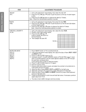
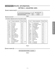
... remote hand set. 2. Call up the adjustment mode display, then select the item HIT. 2. Press TV (ANT)/VIDEO button on TV. 4. Receive cross-hatch pattern signal. 3. Press TV (ANT)/VIDEO button on TV again. 6. GENERAL ADJUSTMENTS SPECIFIC INFORMATIONS HEIGHT (HIT) ITEM WIDTH (WID) VERTICAL LINEARITY (VLIN) ADJUSTMENT PROCEDURE 1. Receive white laster pattern signal, and...
... remote hand set. 2. Call up the adjustment mode display, then select the item HIT. 2. Press TV (ANT)/VIDEO button on TV. 4. Receive cross-hatch pattern signal. 3. Press TV (ANT)/VIDEO button on TV again. 6. GENERAL ADJUSTMENTS SPECIFIC INFORMATIONS HEIGHT (HIT) ITEM WIDTH (WID) VERTICAL LINEARITY (VLIN) ADJUSTMENT PROCEDURE 1. Receive white laster pattern signal, and...
Service Manual
Page 17
... ← PGOF PIP YG OFFSET 00H ← STRH START H 67H ← STRP START PTN 8AH ← VLD VLD 41H ← VCEN V POSITION 81H ← TVOP TV OPTION 00H ← Table-2 CIRCUIT CHECKS FBT DETECTION VOLTAGE (C) 24.5V Table-3 - 17 -
... ← PGOF PIP YG OFFSET 00H ← STRH START H 67H ← STRP START PTN 8AH ← VLD VLD 41H ← VCEN V POSITION 81H ← TVOP TV OPTION 00H ← Table-2 CIRCUIT CHECKS FBT DETECTION VOLTAGE (C) 24.5V Table-3 - 17 -

Service Manual
Page 19
CAPT ENTER FAV t RESET PIP CH t LIGHT RECALL POWER TV CABLE VCR MUTE TV/VIDEO TIMER 12 45 3 CH 6 7 100 C.CAPT 89 CH RTN VOL 0 ENT ADV/ PIP CH MENU FAV ENTER FAV RESET ADV/ EXIT PIP CH STOP SOURCE PLAY PIP REC TV/VCR REW FF STILL LOCATE SWAP RECALL POWER TIMER TV/VIDEO CHANNEL s/t VOLUME s/t CH RTN MENU PIP CH s FAV s s/t/T/S EXIT PIP functions (For "TV" and "CABLE" modes) - 19 - MUTE Channel Number C. GENERAL ADJUSTMENTS SPECIFIC INFORMATIONS Remote Control LIGHT TV/CABLE/VCR switch Set to "TV" to control the TV.
CAPT ENTER FAV t RESET PIP CH t LIGHT RECALL POWER TV CABLE VCR MUTE TV/VIDEO TIMER 12 45 3 CH 6 7 100 C.CAPT 89 CH RTN VOL 0 ENT ADV/ PIP CH MENU FAV ENTER FAV RESET ADV/ EXIT PIP CH STOP SOURCE PLAY PIP REC TV/VCR REW FF STILL LOCATE SWAP RECALL POWER TIMER TV/VIDEO CHANNEL s/t VOLUME s/t CH RTN MENU PIP CH s FAV s s/t/T/S EXIT PIP functions (For "TV" and "CABLE" modes) - 19 - MUTE Channel Number C. GENERAL ADJUSTMENTS SPECIFIC INFORMATIONS Remote Control LIGHT TV/CABLE/VCR switch Set to "TV" to control the TV.

Service Manual
Page 20
...make sure the channel programming has been done properly. CH PROGRAM function 1 Select "CH PROGRAM" following steps 1 and 2 above. 2 Press : or ; The TV will see the message to the right appears. 4 Press CHANNEL s or t to 4 for each input source. If necessary, arrange the preset channels with the ADD...the button until "ADD" is complete, you press the CHANNEL s or t button. To add the channel press the button until "ERASE" is on the TV function as the t/s buttons while a menu is highlighted. Note: The CHANNEL t/s buttons on the screen. * Please refer to add using the CHANNEL s...
...make sure the channel programming has been done properly. CH PROGRAM function 1 Select "CH PROGRAM" following steps 1 and 2 above. 2 Press : or ; The TV will see the message to the right appears. 4 Press CHANNEL s or t to 4 for each input source. If necessary, arrange the preset channels with the ADD...the button until "ADD" is complete, you press the CHANNEL s or t button. To add the channel press the button until "ERASE" is on the TV function as the t/s buttons while a menu is highlighted. Note: The CHANNEL t/s buttons on the screen. * Please refer to add using the CHANNEL s...
Service Manual
Page 49
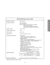
... CHANNEL COVERAGE POWER SOURCE POWER CONSUMPTION AUDIO POWER SPEAKER TYPE VIDEO/AUDIO TERMINALS DIMENSIONS/MASS NTSC standard VHF: 2 through 13 UHF: 14 through 69 Cable TV: Mid band (A-8 through A-1, A through I) Super band (J through W) Hyper band (AA through ZZ, AAA, BBB) Ultra band (65 through 94, 100 through 125) 120 V AC, 60...
... CHANNEL COVERAGE POWER SOURCE POWER CONSUMPTION AUDIO POWER SPEAKER TYPE VIDEO/AUDIO TERMINALS DIMENSIONS/MASS NTSC standard VHF: 2 through 13 UHF: 14 through 69 Cable TV: Mid band (A-8 through A-1, A through I) Super band (J through W) Hyper band (AA through ZZ, AAA, BBB) Ultra band (65 through 94, 100 through 125) 120 V AC, 60...


