
Service Manual
Page 2
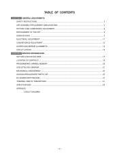
... CHECKS ...16 CHAPTER 2 SPECIFIC INFORMATIONS SETTING & ADJUSTING DATA ...17 LOCATION OF CONTROLS ...18 PROGRAMMING CHANNEL MEMORY ...20 CIRCUIT BLOCK DIAGRAM ...21 MECHANICAL DISASSEMBLY ...23 CHASSIS REPLACEMENT PARTS LIST ...25 PC BOARDS BOTTOM VIEW ...41 TERMINAL VIEW OF TRANSISTORS ...51 SPECIFICATIONS ...53 APPENDIX: CIRCUIT DIAGRAM - 2 -
... CHECKS ...16 CHAPTER 2 SPECIFIC INFORMATIONS SETTING & ADJUSTING DATA ...17 LOCATION OF CONTROLS ...18 PROGRAMMING CHANNEL MEMORY ...20 CIRCUIT BLOCK DIAGRAM ...21 MECHANICAL DISASSEMBLY ...23 CHASSIS REPLACEMENT PARTS LIST ...25 PC BOARDS BOTTOM VIEW ...41 TERMINAL VIEW OF TRANSISTORS ...51 SPECIFICATIONS ...53 APPENDIX: CIRCUIT DIAGRAM - 2 -

Service Manual
Page 3
...voltage measurements for higher voltage, wattage, etc. Voltage measured must not be violently expelled. The nominal value of the high voltage of substitute replacement parts which do not use an accurate and reliable high voltage meter. 2. The only source of the cabinet, such as a water pipe, ... Transformer should not be recorded as ; to be undertaken only after referring to table-1 for X-RAY RADIATION protection. Replacement parts which prevents the receiver from the unprotected body while handling. 3. Refer to the PRODUCT SAFETY NOTICE below. For continued safety...
...voltage measurements for higher voltage, wattage, etc. Voltage measured must not be violently expelled. The nominal value of the high voltage of substitute replacement parts which do not use an accurate and reliable high voltage meter. 2. The only source of the cabinet, such as a water pipe, ... Transformer should not be recorded as ; to be undertaken only after referring to table-1 for X-RAY RADIATION protection. Replacement parts which prevents the receiver from the unprotected body while handling. 3. Refer to the PRODUCT SAFETY NOTICE below. For continued safety...

Service Manual
Page 8
... ANODE LEAD AND ANODE CAP. 2. When replacing Anode Lead or Anode Cap with new one, remove Lead Holder from old lead as follows. The contents of the parts are provided for each R, G and B. HITACHI CRT 50A50 50A60 55A60 61A60 R 23796001 23005114 23005242 23005249 G 23005397 23005115... ↑ ↑ B 23796003 ↑ ↑ 23796486 REPLACEMENT OF HIGH VOLTAGE CABLE ANODE LEAD RUBBER BOOT LEAD ...
... ANODE LEAD AND ANODE CAP. 2. When replacing Anode Lead or Anode Cap with new one, remove Lead Holder from old lead as follows. The contents of the parts are provided for each R, G and B. HITACHI CRT 50A50 50A60 55A60 61A60 R 23796001 23005114 23005242 23005249 G 23005397 23005115... ↑ ↑ B 23796003 ↑ ↑ 23796486 REPLACEMENT OF HIGH VOLTAGE CABLE ANODE LEAD RUBBER BOOT LEAD ...

Service Manual
Page 10
...ᕃ NO. 23XXXXXX ᕄ POWER : 000 ᕅ BUS LINE : OK ᕆ BUS CONT : OK ᕇ BLOCK : MAIN SUB ᕃ Part number of microprocessor (QA01) ᕄ Operation number of QA02 has been complated. 3. When repair of a failure place finishes, the next failure place is indicated. ...turn on the owner's manual. NG MAIN ........ EXIT FROM SERVICE MODE 1) Pressing POWER button to initialize the data unless QA02 has been replaced. 7. Main sync SUB .......... SELECTING THE ADJUSTING ITEMS 1) Every pressing of CHANNEL s button in the service mode changes the adjustment items...
...ᕃ NO. 23XXXXXX ᕄ POWER : 000 ᕅ BUS LINE : OK ᕆ BUS CONT : OK ᕇ BLOCK : MAIN SUB ᕃ Part number of microprocessor (QA01) ᕄ Operation number of QA02 has been complated. 3. When repair of a failure place finishes, the next failure place is indicated. ...turn on the owner's manual. NG MAIN ........ EXIT FROM SERVICE MODE 1) Pressing POWER button to initialize the data unless QA02 has been replaced. 7. Main sync SUB .......... SELECTING THE ADJUSTING ITEMS 1) Every pressing of CHANNEL s button in the service mode changes the adjustment items...

Service Manual
Page 16
.... 2. Then turn the receiver on . 2. Connect an accurate high voltage meter to table-1 for the final check in this state even after replacing. Raster and sound will disappear. 3. Refer to the anode of the rubber cover before disconnecting the cable. 4. High voltages are also present in... turn it is secure. Refer to normal operation when pin 12 of Z801 is approximately (C) volts. Location No. CAUTION: When the following parts fail, check the High Voltage after removing the jumper wire. Holding the rubber cover firmly, turn the receiver off and allow the FS circuit...
.... 2. Then turn the receiver on . 2. Connect an accurate high voltage meter to table-1 for the final check in this state even after replacing. Raster and sound will disappear. 3. Refer to the anode of the rubber cover before disconnecting the cable. 4. High voltages are also present in... turn it is secure. Refer to normal operation when pin 12 of Z801 is approximately (C) volts. Location No. CAUTION: When the following parts fail, check the High Voltage after removing the jumper wire. Holding the rubber cover firmly, turn the receiver off and allow the FS circuit...

Service Manual
Page 23
...symbols " " in the schematic diagram and the parts list designate components which have special characteristics important for safety and should be replaced only with types identical to assist in the parts list. Models : 50A60/50A50/55A60/61A60 Capacitors CD : Ceramic Disk PF : Plastic ...177;5%, 1/6W unless otherwise noted.) Electrolytic Metal Film Fusible Resistor Location No. GENERAL ADJUSTMENTS SPECIFIC INFORMATIONS CHASSIS REPLACEMENT PARTS LIST WARNING: BEFORE SERVICING THIS CHASSIS, READ THE "X-RAY RADIATION PRECAUTION", "SAFETY PRECAUTION" AND "PRODUCT SAFETY NOTICE" ON PAGE 3...
...symbols " " in the schematic diagram and the parts list designate components which have special characteristics important for safety and should be replaced only with types identical to assist in the parts list. Models : 50A60/50A50/55A60/61A60 Capacitors CD : Ceramic Disk PF : Plastic ...177;5%, 1/6W unless otherwise noted.) Electrolytic Metal Film Fusible Resistor Location No. GENERAL ADJUSTMENTS SPECIFIC INFORMATIONS CHASSIS REPLACEMENT PARTS LIST WARNING: BEFORE SERVICING THIS CHASSIS, READ THE "X-RAY RADIATION PRECAUTION", "SAFETY PRECAUTION" AND "PRODUCT SAFETY NOTICE" ON PAGE 3...


