
Service Manual
Page 2
GENERAL ADJUSTMENTS SPECIFIC INFORMATIONS TABLE OF CONTENTS CHAPTER 1 GENERAL ADJUSTMENTS SAFETY INSTRUCTIONS ...3 CRT ASSEMBLY REPLACEMENT AND MOUNTING 4 PICTURE TUBE COMPONENTS ADJUSTMENT ...6 REPLACEMENT OF THE CRT ...8 SERVICE MODE ...9 ELECTRICAL ADJUSTMENT ...11 CONVERGENCE ADJUSTMENT ...13 SCREEN AND MIRROR ALIGNMENTS ...15 CIRCUIT CHECKS ...16 CHAPTER 2 SPECIFIC ...
GENERAL ADJUSTMENTS SPECIFIC INFORMATIONS TABLE OF CONTENTS CHAPTER 1 GENERAL ADJUSTMENTS SAFETY INSTRUCTIONS ...3 CRT ASSEMBLY REPLACEMENT AND MOUNTING 4 PICTURE TUBE COMPONENTS ADJUSTMENT ...6 REPLACEMENT OF THE CRT ...8 SERVICE MODE ...9 ELECTRICAL ADJUSTMENT ...11 CONVERGENCE ADJUSTMENT ...13 SCREEN AND MIRROR ALIGNMENTS ...15 CIRCUIT CHECKS ...16 CHAPTER 2 SPECIFIC ...

Service Manual
Page 3
... such features are identified in this limit constitutes a potential shock hazard and must be observed before any service is the picture tube. AC. Before replacing any circumstances, exceed (B) kV. The only source of these special safety characteristics are identified by... PRECAUTION 1. Excessive high voltage can produce potentially hazardous X-RAY RADIATION. An isolation Transformer should not be corrected immediately. The picture tube is highly evacuated and if broken, glass fragments will be certain that the circuit is equipped with the necessary precautions ...
... such features are identified in this limit constitutes a potential shock hazard and must be observed before any service is the picture tube. AC. Before replacing any circumstances, exceed (B) kV. The only source of these special safety characteristics are identified by... PRECAUTION 1. Excessive high voltage can produce potentially hazardous X-RAY RADIATION. An isolation Transformer should not be corrected immediately. The picture tube is highly evacuated and if broken, glass fragments will be certain that the circuit is equipped with the necessary precautions ...

Service Manual
Page 5
... - 5 - CAUTION: Align the Anode cable as illustrated on around the Anode Cap as illustrated. V. Screw for D.Y Screw for R, G, B) Reverse the removal procedures except the followings. 1. PICTURE TILT ADJUSTMENT (page 6.) 3. GENERAL ADJUSTMENTS TO REMOVE CRT (Same procedure for screws of electron gun. M. YOKE from CRT Mounting. Detach CRT Anode Cap from old...
... - 5 - CAUTION: Align the Anode cable as illustrated on around the Anode Cap as illustrated. V. Screw for D.Y Screw for R, G, B) Reverse the removal procedures except the followings. 1. PICTURE TILT ADJUSTMENT (page 6.) 3. GENERAL ADJUSTMENTS TO REMOVE CRT (Same procedure for screws of electron gun. M. YOKE from CRT Mounting. Detach CRT Anode Cap from old...

Service Manual
Page 6
... position on the neck is required most front (CRT funnel side) and the screw is fastened after rotating yoke adjusting picture tilt. ᕄ Centering magnet After adjusting picture tilt, picture position is fixed on the Remote Control to dis- Before adjusting the R, G, B FOCUS, remove the 4 screws ...TILT ADJUSTMENT Rotate R, G, B deflection yoke so that the cross-bar pat- R, G, B FOCUS ADJUSTMENT 1. Press "0" and "RTN" buttons to make the picture a single Red color. 100 button to erase Red color 0 button to erase Green color RTN button to screen center. 6. Then fasten the screw. (See ...
... position on the neck is required most front (CRT funnel side) and the screw is fastened after rotating yoke adjusting picture tilt. ᕄ Centering magnet After adjusting picture tilt, picture position is fixed on the Remote Control to dis- Before adjusting the R, G, B FOCUS, remove the 4 screws ...TILT ADJUSTMENT Rotate R, G, B deflection yoke so that the cross-bar pat- R, G, B FOCUS ADJUSTMENT 1. Press "0" and "RTN" buttons to make the picture a single Red color. 100 button to erase Red color 0 button to erase Green color RTN button to screen center. 6. Then fasten the screw. (See ...

Service Manual
Page 10
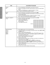
EXIT FROM SERVICE MODE 1) Pressing POWER button to FFH. s INITIALIZATION OF MEMORY DATA OF QA02 After replacing QA02, the following displays are plural. Check the picture carefully. Main sync SUB .......... ADJUSTING THE DATA 1) Pressing of VOLUME s or t button will begin to check if interface among IC's are executed properly. 2) During diagnosis, ...
EXIT FROM SERVICE MODE 1) Pressing POWER button to FFH. s INITIALIZATION OF MEMORY DATA OF QA02 After replacing QA02, the following displays are plural. Check the picture carefully. Main sync SUB .......... ADJUSTING THE DATA 1) Pressing of VOLUME s or t button will begin to check if interface among IC's are executed properly. 2) During diagnosis, ...

Service Manual
Page 11
...RESET status). 3. Select "TNTC" register. 7. TP-V (on SIGNAL board) TP-G (on the MAIN board. 2. Check the picture with off -air signal. 1. Constrict the picture height until the vertical retrace line appears adjusting the HEIGHT control on SIGNAL board) DIGITAL C VOLT METER SUB-BRIGHTNESS (BRTC) SUB-COLOR... (SCOL) SUB-TINT (TNTC) SUB-CONTRAST (SCNT) PICTURE POSITION 1. Adjust the CONTRAST to the minimum and BRIGHTNESS to normal mode(RESET). 2. Adjust the data value to magenta bar ratio of ...
...RESET status). 3. Select "TNTC" register. 7. TP-V (on SIGNAL board) TP-G (on the MAIN board. 2. Check the picture with off -air signal. 1. Constrict the picture height until the vertical retrace line appears adjusting the HEIGHT control on SIGNAL board) DIGITAL C VOLT METER SUB-BRIGHTNESS (BRTC) SUB-COLOR... (SCOL) SUB-TINT (TNTC) SUB-CONTRAST (SCNT) PICTURE POSITION 1. Adjust the CONTRAST to the minimum and BRIGHTNESS to normal mode(RESET). 2. Adjust the data value to magenta bar ratio of ...
Service Manual
Page 12
... on TV or remote hand set. 2. Exit from 7 to lack. 3. Adjust the data of FOCUS PAC (page 7) clock- Note : Check the vertical picture position is correct. 1. Call up the adjustment mode display, then select the item WID. 2. Call up the adjustment mode display, then select the item HIT... VERTICAL LINEARITY (VLIN) ADJUSTMENT PROCEDURE 1. Press RESET button on TV. 4. Receive cross-hatch pattern signal. 3. Press the VOLUME s or t button to get the picture so the left and right edges of items RCUT, GCUT and BCUT to advance the data by 10 steps. Adjust the data of the best...
... on TV or remote hand set. 2. Exit from 7 to lack. 3. Adjust the data of FOCUS PAC (page 7) clock- Note : Check the vertical picture position is correct. 1. Call up the adjustment mode display, then select the item WID. 2. Call up the adjustment mode display, then select the item HIT... VERTICAL LINEARITY (VLIN) ADJUSTMENT PROCEDURE 1. Press RESET button on TV. 4. Receive cross-hatch pattern signal. 3. Press the VOLUME s or t button to get the picture so the left and right edges of items RCUT, GCUT and BCUT to advance the data by 10 steps. Adjust the data of the best...

Service Manual
Page 13
...(up)", "8 (down)", "4 (left)" or "6 (right)" to enter the adjusted states. Press "7" button to stop the blinking of cursor. 5. PICTURE POSITION ADJUSTMENT 4. This means that the Red color is about 1 second. 11. Make sure the best convergence setting is adjustable. Press "5" button to...") 55.8 x14 (55") 62 x14 (61") Note: Adjusting procedure in cross-hatch pattern. HIT, WID ADJUSTMENT 5. At this time, picture changes for about the center of cursor ON/OFF: 5 button 2. GENERAL ADJUSTMENTS SPECIFIC INFORMATIONS CONVERGENCE ADJUSTMENT Adjust convergence from the screen. 100...
...(up)", "8 (down)", "4 (left)" or "6 (right)" to enter the adjusted states. Press "7" button to stop the blinking of cursor. 5. PICTURE POSITION ADJUSTMENT 4. This means that the Red color is about 1 second. 11. Make sure the best convergence setting is adjustable. Press "5" button to...") 55.8 x14 (55") 62 x14 (61") Note: Adjusting procedure in cross-hatch pattern. HIT, WID ADJUSTMENT 5. At this time, picture changes for about the center of cursor ON/OFF: 5 button 2. GENERAL ADJUSTMENTS SPECIFIC INFORMATIONS CONVERGENCE ADJUSTMENT Adjust convergence from the screen. 100...

Service Manual
Page 14
....) 4. Adjust alignment of blue and red. (Refer Alignment adjustment for blue and red yokes on base of color and picture size. GENERAL ADJUSTMENTS SPECIFIC INFORMATIONS NOTES In many cases, color misconvergence may be reduced considerably. 1. Perform following method allows ...as well, repeat steps 2 to green data. 6. REPLACING CONVERGENCE UNIT When replacing convergence unit, all picture screens require readjustment basically, but the following procedures. 1. Check each picture screen for color matching. If necessary, add some adjustments of blue and red. 2. Mount yoke ...
....) 4. Adjust alignment of blue and red. (Refer Alignment adjustment for blue and red yokes on base of color and picture size. GENERAL ADJUSTMENTS SPECIFIC INFORMATIONS NOTES In many cases, color misconvergence may be reduced considerably. 1. Perform following method allows ...as well, repeat steps 2 to green data. 6. REPLACING CONVERGENCE UNIT When replacing convergence unit, all picture screens require readjustment basically, but the following procedures. 1. Check each picture screen for color matching. If necessary, add some adjustments of blue and red. 2. Mount yoke ...

Service Manual
Page 16
... CHECK The Fail Safe (FS) circuit check is indispensable for high voltage (B). (See SETTING & ADJUSTING DATA on . 2. Turn the receiver on page 17) 4. To obtain a picture again, temporarily turn it is secure. Troubleshooting Guide for fall safe voltage (C) . Set the BRIGHTNESS and CONTRAST to disconnect. 5. T461 C447 C406 C407 Name Flyback... voltage must remain in servicing. Measure high voltage at the point where the cable enters the FBT. 2. Then turn the receiver on to produce a normal picture. Determine the extent of the...
... CHECK The Fail Safe (FS) circuit check is indispensable for high voltage (B). (See SETTING & ADJUSTING DATA on . 2. Turn the receiver on page 17) 4. To obtain a picture again, temporarily turn it is secure. Troubleshooting Guide for fall safe voltage (C) . Set the BRIGHTNESS and CONTRAST to disconnect. 5. T461 C447 C406 C407 Name Flyback... voltage must remain in servicing. Measure high voltage at the point where the cable enters the FBT. 2. Then turn the receiver on to produce a normal picture. Determine the extent of the...
Service Manual
Page 17
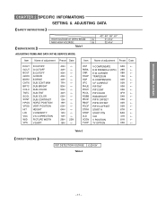
POSITION HEIGHT V-LINEARITY V-S CORRECTION PICTURE WIDTH V-SHIFT 40H ← 40H ← 40H ← 40H ← 40H ← 7FH ← 80H ← 50H ← 44H ← 05H ← 10H ← 19H &#...
POSITION HEIGHT V-LINEARITY V-S CORRECTION PICTURE WIDTH V-SHIFT 40H ← 40H ← 40H ← 40H ← 40H ← 7FH ← 80H ← 50H ← 44H ← 05H ← 10H ← 19H &#...

