Quick Installation Guide
Page 3
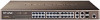
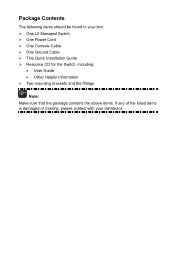
Package Contents The following items should be found in your box: ¾ One L2 Managed Switch ¾ One Power Cord ¾ One Console Cable ¾ One Ground Cable ¾ This Quick Installation Guide ¾ Resource CD for the Switch, including: • User Guide • Other Helpful Information ¾ Two mounting brackets and the fittings Note: Make sure that the package contains the above items. If any of the listed items is damaged or missing, please contact with your distributor.
Package Contents The following items should be found in your box: ¾ One L2 Managed Switch ¾ One Power Cord ¾ One Console Cable ¾ One Ground Cable ¾ This Quick Installation Guide ¾ Resource CD for the Switch, including: • User Guide • Other Helpful Information ¾ Two mounting brackets and the fittings Note: Make sure that the package contains the above items. If any of the listed items is damaged or missing, please contact with your distributor.
Quick Installation Guide
Page 4
... to take note. Symbol Description Note Remind to do the physical connection of the Switch. The note contains the helpful information for TL-SL5428E 24-port 10/100Mbps + 4-port Gigabit L2 Managed Switch without any explanation. A caution indicates a Caution potential which may result in this... Thank you for setting up the L2 Managed Switch. 1. Conventions The Switch or TL-SL5428E mentioned in device damage. Remind to install the Switch. Chapter 2 Installation This chapter illustrates how to be careful. Chapter 4 Login to the Switch This chapter instructs you to log in to the...
... to take note. Symbol Description Note Remind to do the physical connection of the Switch. The note contains the helpful information for TL-SL5428E 24-port 10/100Mbps + 4-port Gigabit L2 Managed Switch without any explanation. A caution indicates a Caution potential which may result in this... Thank you for setting up the L2 Managed Switch. 1. Conventions The Switch or TL-SL5428E mentioned in device damage. Remind to install the Switch. Chapter 2 Installation This chapter illustrates how to be careful. Chapter 4 Login to the Switch This chapter instructs you to log in to the...
Quick Installation Guide
Page 5
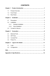
CONTENTS Chapter 1 Product Introduction 1 1.1 Product Overview 1 1.2 Front Panel 1 1.3 Rear Panel 2 Chapter 2 Installation 3 2.1 Precautions 3 2.2 Installation 3 2.2.1 Desktop Installation 4 2.2.2 Rack Installation 4 2.3 Connect to Ground 5 Chapter 3 Connection 8 3.1 Ethernet Ports 8 3.2 SFP Ports 8 3.3 Console Port 9 3.4 Power On 10 Chapter 4 Login to the Switch 11 4.1 Login 11 4.2 Configuration 11 FAQ ...13 Appendix A: Specifications 14
CONTENTS Chapter 1 Product Introduction 1 1.1 Product Overview 1 1.2 Front Panel 1 1.3 Rear Panel 2 Chapter 2 Installation 3 2.1 Precautions 3 2.2 Installation 3 2.2.1 Desktop Installation 4 2.2.2 Rack Installation 4 2.3 Connect to Ground 5 Chapter 3 Connection 8 3.1 Ethernet Ports 8 3.2 SFP Ports 8 3.3 Console Port 9 3.4 Power On 10 Chapter 4 Login to the Switch 11 4.1 Login 11 4.2 Configuration 11 FAQ ...13 Appendix A: Specifications 14
Quick Installation Guide
Page 6
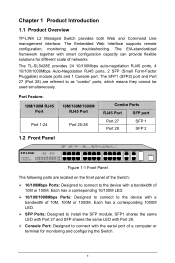
...100/1000Mbps Ports: Designed to connect to connect with a bandwidth of 10M or 100M. Chapter 1 Product Introduction 1.1 Product Overview TP-LINK L2 Managed Switch provides both Web and Command Line management interface. The Embedded Web Interface supports remote configuration, monitoring and troubleshooting. The SFP1 (...SFP 1 Port 28 SFP 2 1.2 Front Panel Figure 1-1 Front Panel The following parts are referred to install the SFP module. The TL-SL5428E provides 24 10/100Mbps auto-negotiation RJ45 ports, 4 10/100/1000Mbps Auto-Negotiation RJ45 ports, 2 SFP (Small Form-Factor Pluggable) ...
...100/1000Mbps Ports: Designed to connect to connect with a bandwidth of 10M or 100M. Chapter 1 Product Introduction 1.1 Product Overview TP-LINK L2 Managed Switch provides both Web and Command Line management interface. The Embedded Web Interface supports remote configuration, monitoring and troubleshooting. The SFP1 (...SFP 1 Port 28 SFP 2 1.2 Front Panel Figure 1-1 Front Panel The following parts are referred to install the SFP module. The TL-SL5428E provides 24 10/100Mbps auto-negotiation RJ45 ports, 4 10/100/1000Mbps Auto-Negotiation RJ45 ports, 2 SFP (Small Form-Factor Pluggable) ...
Quick Installation Guide
Page 7
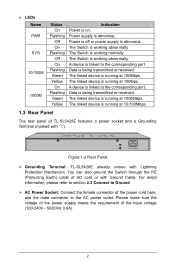
.... Figure 1-2 Rear Panel ¾ Grounding Terminal: TL-SL5428E already comes with Ground Cable. You can also ground the Switch through the PE (Protecting Earth) cable of TL-SL5428E features a power socket and a Grounding Terminal (marked with ). Data is running at 100Mbps. The linked device is being transmitted or received. The linked device is working normally. Please make...
.... Figure 1-2 Rear Panel ¾ Grounding Terminal: TL-SL5428E already comes with Ground Cable. You can also ground the Switch through the PE (Protecting Earth) cable of TL-SL5428E features a power socket and a Grounding Terminal (marked with ). Data is running at 100Mbps. The linked device is being transmitted or received. The linked device is working normally. Please make...

Quick Installation Guide
Page 8
... cleaning method. • Take waterproof measures during storage, transportation and operation of the equipment. • Use only the power cord provided with the Switch. • Make sure the voltage of the power supply meets the requirement of the input voltage of the... installed on the standard 19-inch mountable rack or located on a flat and stable surface that can support the entire weight of the Switch with all fittings. • Locate the Switch far from water and moisture sources, be sure to provide an acceptable temperature and humidity operating environment. 2.2 Installation This...
... cleaning method. • Take waterproof measures during storage, transportation and operation of the equipment. • Use only the power cord provided with the Switch. • Make sure the voltage of the power supply meets the requirement of the input voltage of the... installed on the standard 19-inch mountable rack or located on a flat and stable surface that can support the entire weight of the Switch with all fittings. • Locate the Switch far from water and moisture sources, be sure to provide an acceptable temperature and humidity operating environment. 2.2 Installation This...
Quick Installation Guide
Page 9
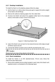
...enough ventilation space around. 5) Connect the Switch to each corner of the Switch. 2.2.1 Desktop Installation To install the Switch on the desktop, please follow the steps: 1) Set the Switch on a flat surface strong enough to support the entire weight of the Switch with all fittings. 2) Remove the ...adhesive backing papers from the rubber feet. 3) Turnover the Switch and attach the supplied rubber feet to the recessed areas on the Switch. 2.2.2 Rack Installation To install the Switch in an EIA standard-sized, 19-inch rack, follow the instructions described below: 1)...
...enough ventilation space around. 5) Connect the Switch to each corner of the Switch. 2.2.1 Desktop Installation To install the Switch on the desktop, please follow the steps: 1) Set the Switch on a flat surface strong enough to support the entire weight of the Switch with all fittings. 2) Remove the ...adhesive backing papers from the rubber feet. 3) Turnover the Switch and attach the supplied rubber feet to the recessed areas on the Switch. 2.2.2 Rack Installation To install the Switch in an EIA standard-sized, 19-inch rack, follow the instructions described below: 1)...
Quick Installation Guide
Page 10
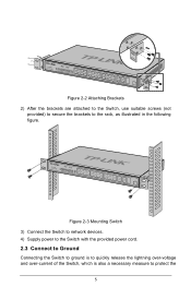
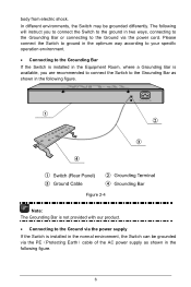
Figure 2-3 Mounting Switch 3) Connect the Switch to network devices. 4) Supply power to the Switch with the provided power cord. 2.3 Connect to Ground Connecting the Switch to ground is to quickly release the lightning over-voltage and over-current of the Switch, which is also a necessary measure to the rack, as illustrated in the following figure. Figure 2-2 Attaching Brackets 2) After the brackets are attached to the Switch, use suitable screws (not provided) to secure the brackets to protect the 5
Figure 2-3 Mounting Switch 3) Connect the Switch to network devices. 4) Supply power to the Switch with the provided power cord. 2.3 Connect to Ground Connecting the Switch to ground is to quickly release the lightning over-voltage and over-current of the Switch, which is also a necessary measure to the rack, as illustrated in the following figure. Figure 2-2 Attaching Brackets 2) After the brackets are attached to the Switch, use suitable screws (not provided) to secure the brackets to protect the 5
Quick Installation Guide
Page 11
...optimum way according to your specific operation environment. • Connecting to the Grounding Bar If the Switch is installed in the Equipment Room, where a Grounding Bar is installed in the normal environment, the Switch can be grounded differently. Figure 2-4 Note: The Grounding Bar is not provided with our product.... • Connecting to the Ground via the power supply If the Switch is available, you to connect the Switch to the ground in two ways, connecting to the Grounding Bar or connecting to the Grounding Bar as shown in the ...
...optimum way according to your specific operation environment. • Connecting to the Grounding Bar If the Switch is installed in the Equipment Room, where a Grounding Bar is installed in the normal environment, the Switch can be grounded differently. Figure 2-4 Note: The Grounding Bar is not provided with our product.... • Connecting to the Ground via the power supply If the Switch is available, you to connect the Switch to the ground in two ways, connecting to the Grounding Bar or connecting to the Grounding Bar as shown in the ...

Quick Installation Guide
Page 12
Figure 2-5 * The figure is to the ground via the PE (Protecting Earth) cable of AC power cord, please make sure the PE (Protecting Earth) cable in the electrical outlet is well grounded in your country, so they may differ from the figure above. Note: If you get from the package and the socket in your situation will comply with the regulation in advance. 7 The power plug you intend to connect the Switch to illustrate the application and principle.
Figure 2-5 * The figure is to the ground via the PE (Protecting Earth) cable of AC power cord, please make sure the PE (Protecting Earth) cable in the electrical outlet is well grounded in your country, so they may differ from the figure above. Note: If you get from the package and the socket in your situation will comply with the regulation in advance. 7 The power plug you intend to connect the Switch to illustrate the application and principle.
Quick Installation Guide
Page 13
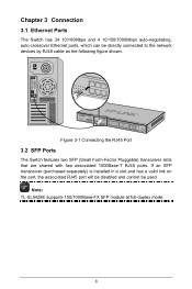
...a slot and has a valid link on the port, the associated RJ45 port will be disabled and cannot be directly connected to the network devices by RJ45 cable as the following figure shown. Figure 3-1 Connecting the RJ45 Port 3.2 SFP Ports The Switch features two SFP (Small Form-...Factor Pluggable) transceiver slots that are shared with two associated 1000Base-T RJ45 ports. Note: TL-SL5428E supports 100/1000Base-FX SFP module at full-duplex mode. 8 Chapter 3 Connection 3.1 Ethernet Ports The Switch has 24 10/100Mbps and 4 10/100/1000Mbps auto-negotiating, auto-crossover Ethernet ports, which...
...a slot and has a valid link on the port, the associated RJ45 port will be disabled and cannot be directly connected to the network devices by RJ45 cable as the following figure shown. Figure 3-1 Connecting the RJ45 Port 3.2 SFP Ports The Switch features two SFP (Small Form-...Factor Pluggable) transceiver slots that are shared with two associated 1000Base-T RJ45 ports. Note: TL-SL5428E supports 100/1000Base-FX SFP module at full-duplex mode. 8 Chapter 3 Connection 3.1 Ethernet Ports The Switch has 24 10/100Mbps and 4 10/100/1000Mbps auto-negotiating, auto-crossover Ethernet ports, which...

Quick Installation Guide
Page 14
Caution: The serial port of the Switch and your computer with a console cable as shown in Figure 3-3. Connect the console port of the computer doesn't support plug-and-play feature, please make sure the Switch is powered off before connecting the console cable to the computer. Figure 3-3 Connecting the Console Port 9 Figure 3-2 Inserting SFP Module 3.3 Console Port The Switch features a console interface for configuring the Switch using CLI (Command Line Interface).
Caution: The serial port of the Switch and your computer with a console cable as shown in Figure 3-3. Connect the console port of the computer doesn't support plug-and-play feature, please make sure the Switch is powered off before connecting the console cable to the computer. Figure 3-3 Connecting the Console Port 9 Figure 3-2 Inserting SFP Module 3.3 Console Port The Switch features a console interface for configuring the Switch using CLI (Command Line Interface).

Quick Installation Guide
Page 15
...don't respond as follows: 1) All of the 10/100M and 1000M LED indicators will flash momentarily and then turn off, which represents a resetting of the Switch, and the positive connector into a power outlet as shown in your country, so they may differ from the figure above , please check the power supply... situation will flash, which represents a successful initialization. Figure 3-4 Connecting to Power Supply * The figure is to illustrate the application and principle. Powering on the Switch, it will automatically initialize and its LED indicators will respond as described above .
...don't respond as follows: 1) All of the 10/100M and 1000M LED indicators will flash momentarily and then turn off, which represents a resetting of the Switch, and the positive connector into a power outlet as shown in your country, so they may differ from the figure above , please check the power supply... situation will flash, which represents a successful initialization. Figure 3-4 Connecting to Power Supply * The figure is to illustrate the application and principle. Powering on the Switch, it will automatically initialize and its LED indicators will respond as described above .
Quick Installation Guide
Page 16
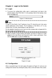
... please refer to Appendix B in the User Guide on the left side of the browser, then press the Enter key. Chapter 4 Login to the Switch 4.1 Login 1) To access the configuration utility, open a web-browser and type in the default address http://192.168.0.1 in lower case letters. The... IP address is 192.168.0.x ("x" is any number from 2 to the Switch, the IP address of the Switch. Figure 4-2 Login 4.2 Configuration After a successful login, the main page will appear, as Figure 4-3, and you can configure the function by...
... please refer to Appendix B in the User Guide on the left side of the browser, then press the Enter key. Chapter 4 Login to the Switch 4.1 Login 1) To access the configuration utility, open a web-browser and type in the default address http://192.168.0.1 in lower case letters. The... IP address is 192.168.0.x ("x" is any number from 2 to the Switch, the IP address of the Switch. Figure 4-2 Login 4.2 Configuration After a successful login, the main page will appear, as Figure 4-3, and you can configure the function by...
Quick Installation Guide
Page 18
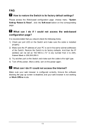
... the corresponding page. Ensure the software blocking the pop-up screen is disabled, and your web browser is configured correctly. FAQ How to restore the Switch to its factory defaults. Make sure your PC is the right type. 4) Turn off the power. It is recommended that you should check the following... items: 1) Check per port LED on the Switch and make sure the cable is installed properly. 2) Make sure the IP address of your web browser is not working on the...
... the corresponding page. Ensure the software blocking the pop-up screen is disabled, and your web browser is configured correctly. FAQ How to restore the Switch to its factory defaults. Make sure your PC is the right type. 4) Turn off the power. It is recommended that you should check the following... items: 1) Check per port LED on the Switch and make sure the cable is installed properly. 2) Make sure the IP address of your web browser is not working on the...
User Guide
Page 13
...Levels and some Conventions. Overview of this Guide stands for TL-SL5428E 24-port 10/100Mbps + 4-port Gigabit L2 Managed Switch. Chapter 6: VLAN-VPN Commands Provide information about the commands used for configuring LAG (Link Aggregation Group). Chapter 9: LAG Commands Provide information about .... Chapter 7: Voice VLAN Commands Provide information about the commands used for configuring Protocol VLAN. TL-SL5428E 24-port 10/100Mbps + 4-port Gigabit L2 Managed Switch CLI Guide Preface This Guide is intended for network administrator to provide referenced information about the...
...Levels and some Conventions. Overview of this Guide stands for TL-SL5428E 24-port 10/100Mbps + 4-port Gigabit L2 Managed Switch. Chapter 6: VLAN-VPN Commands Provide information about the commands used for configuring LAG (Link Aggregation Group). Chapter 9: LAG Commands Provide information about .... Chapter 7: Voice VLAN Commands Provide information about the commands used for configuring Protocol VLAN. TL-SL5428E 24-port 10/100Mbps + 4-port Gigabit L2 Managed Switch CLI Guide Preface This Guide is intended for network administrator to provide referenced information about the...
User Guide
Page 14
... other operations. Chapter 21: System Commands Provide information about the commands used for Address configuration. TL-SL5428E 24-port 10/100Mbps + 4-port Gigabit L2 Managed Switch CLI Guide Chapter 12: Binding Table Commands Provide information about the commands used for configuring IEEE 802...the Host together. Chapter 25: ACL Commands 2 Chapter 17: Log Commands Provide information about the commands used for protecting the switch from the ARP cheating or ARP Attack. Chapter 13: ARP Inspection Commands Provide information about the commands used for configuring system...
... other operations. Chapter 21: System Commands Provide information about the commands used for Address configuration. TL-SL5428E 24-port 10/100Mbps + 4-port Gigabit L2 Managed Switch CLI Guide Chapter 12: Binding Table Commands Provide information about the commands used for configuring IEEE 802...the Host together. Chapter 25: ACL Commands 2 Chapter 17: Log Commands Provide information about the commands used for protecting the switch from the ARP cheating or ARP Attack. Chapter 13: ARP Inspection Commands Provide information about the commands used for configuring system...
User Guide
Page 15
... Network Management Protocol) functions. Chapter 27: IGMP Commands Provide information about the commands used for configuring the ACL (Access Control List). TL-SL5428E 24-port 10/100Mbps + 4-port Gigabit L2 Managed Switch CLI Guide Provide information about the commands used for configuring the IGMP Snooping (Internet Group Management Protocol Snooping). Chapter 26: MSTP...
... Network Management Protocol) functions. Chapter 27: IGMP Commands Provide information about the commands used for configuring the ACL (Access Control List). TL-SL5428E 24-port 10/100Mbps + 4-port Gigabit L2 Managed Switch CLI Guide Provide information about the commands used for configuring the IGMP Snooping (Internet Group Management Protocol Snooping). Chapter 26: MSTP...

User Guide
Page 16
... → All Programs → Accessories→ Communications → Hyper Terminal to the switch by a RS-232 serial console port on the switch. 2. Enter a name into the Name field and click OK. 4 TL-SL5428E 24-port 10/100Mbps + 4-port Gigabit L2 Managed Switch CLI Guide Chapter 1 Using the CLI 1.1 Accessing the CLI You can log on...
... → All Programs → Accessories→ Communications → Hyper Terminal to the switch by a RS-232 serial console port on the switch. 2. Enter a name into the Name field and click OK. 4 TL-SL5428E 24-port 10/100Mbps + 4-port Gigabit L2 Managed Switch CLI Guide Chapter 1 Using the CLI 1.1 Accessing the CLI You can log on...
User Guide
Page 17
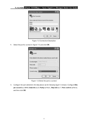
Select the port to connect 5. Configure the port selected in figure 1-3, and click OK. Figure 1-3 Select the port to connect in the step above as None, and then click OK. 5 Configure Bits per second as 38400, Data bits as 8, Parity as None, Stop bits as 1, Flow control as the following figure1-4 shown. TL-SL5428E 24-port 10/100Mbps + 4-port Gigabit L2 Managed Switch CLI Guide Figure 1-2 Connection Description 4.
Select the port to connect 5. Configure the port selected in figure 1-3, and click OK. Figure 1-3 Select the port to connect in the step above as None, and then click OK. 5 Configure Bits per second as 38400, Data bits as 8, Parity as None, Stop bits as 1, Flow control as the following figure1-4 shown. TL-SL5428E 24-port 10/100Mbps + 4-port Gigabit L2 Managed Switch CLI Guide Figure 1-2 Connection Description 4.

