
User Guide
Page 2
is a registered trademark of their respective holders. Other brands and product names are subject to make any means or used to change without permission from TP-LINK TECHNOLOGIES CO., LTD. http://www.tp-link.com I No part of the specifications may be reproduced in any form or by any derivative such as translation, transformation, or adaptation without notice. All rights reserved. COPYRIGHT & TRADEMARKS Specifications are trademarks or registered trademarks of TP-LINK TECHNOLOGIES CO., LTD. Copyright © 2011 TP-LINK TECHNOLOGIES CO., LTD.
is a registered trademark of their respective holders. Other brands and product names are subject to make any means or used to change without permission from TP-LINK TECHNOLOGIES CO., LTD. http://www.tp-link.com I No part of the specifications may be reproduced in any form or by any derivative such as translation, transformation, or adaptation without notice. All rights reserved. COPYRIGHT & TRADEMARKS Specifications are trademarks or registered trademarks of TP-LINK TECHNOLOGIES CO., LTD. Copyright © 2011 TP-LINK TECHNOLOGIES CO., LTD.

User Guide
Page 3
... the instruction manual, may cause undesired operation. The fuse resistor should be required to correct the interference at his own expense. This equipment generates, uses, and can radiate radio frequency energy and, if not installed and used in which case the user may be used in a commercial environment. This device complies with part 15 of the power module. Any changes or...
... the instruction manual, may cause undesired operation. The fuse resistor should be required to correct the interference at his own expense. This equipment generates, uses, and can radiate radio frequency energy and, if not installed and used in which case the user may be used in a commercial environment. This device complies with part 15 of the power module. Any changes or...
User Guide
Page 4
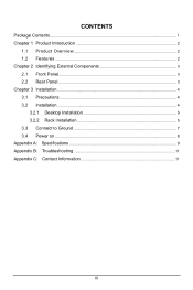
CONTENTS Package Contents...1 Chapter 1 Product Introduction 2 1.1 Product Overview 2 1.2 Features ...2 Chapter 2 Identifying External Components 3 2.1 Front Panel...3 2.2 Rear Panel ...3 Chapter 3 Installation ...4 3.1 Precautions ...4 3.2 Installation ...4 3.2.1 Desktop Installation 5 3.2.2 Rack Installation 5 3.3 Connect to Ground 7 3.4 Power on ...8 Appendix A: Specifications 9 Appendix B: Troubleshooting 11 Appendix C: Contact Information 11 III
CONTENTS Package Contents...1 Chapter 1 Product Introduction 2 1.1 Product Overview 2 1.2 Features ...2 Chapter 2 Identifying External Components 3 2.1 Front Panel...3 2.2 Rear Panel ...3 Chapter 3 Installation ...4 3.1 Precautions ...4 3.2 Installation ...4 3.2.1 Desktop Installation 5 3.2.2 Rack Installation 5 3.3 Connect to Ground 7 3.4 Power on ...8 Appendix A: Specifications 9 Appendix B: Troubleshooting 11 Appendix C: Contact Information 11 III

User Guide
Page 5
TL-SG1016D and TL-SG1024D do not include mounting screws and two "L" planks. 1 Package Contents The following contents should be found in your package: ¾ One TL-SG1008/TL-SG1016D/TL-SG1024D Switch ¾ One power cord ¾ This User Guide ¾ Rubber footpads for Desk-mount ¾ Mounting screws and two "L" planks Note: Make sure that the package contains the above items. If any of the listed items are damaged or missing, please contact with your distributor.
TL-SG1016D and TL-SG1024D do not include mounting screws and two "L" planks. 1 Package Contents The following contents should be found in your package: ¾ One TL-SG1008/TL-SG1016D/TL-SG1024D Switch ¾ One power cord ¾ This User Guide ¾ Rubber footpads for Desk-mount ¾ Mounting screws and two "L" planks Note: Make sure that the package contains the above items. If any of the listed items are damaged or missing, please contact with your distributor.
User Guide
Page 6
...; Internal power supply 2 The TL-SG1008/TL-SG1016D/TL-SG1024D Switch is plug-and-play and no configuration is compatible with all ports eliminate the need for half-duplex mode. Diagnostic LEDs which display link status and activity, allowing you to faster Gigabit speeds. It protects your network server and backbone connections make Gigabit a reality. Increase the speed of your existing network investments while providing you with a straightforward migration path to quickly detect...
...; Internal power supply 2 The TL-SG1008/TL-SG1016D/TL-SG1024D Switch is plug-and-play and no configuration is compatible with all ports eliminate the need for half-duplex mode. Diagnostic LEDs which display link status and activity, allowing you to faster Gigabit speeds. It protects your network server and backbone connections make Gigabit a reality. Increase the speed of your existing network investments while providing you with a straightforward migration path to quickly detect...
User Guide
Page 7
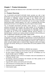
... a Grounding Terminal (marked with Lightning Protection Mechanism. TL-SG1008/TL-SG1016D/TL-SG1024D just differ in the number of LED indicators and ports and all figures in this guide are used for monitoring and pre-troubleshooting of each indicator. ¾ POWER LED: This indicator will light solid green when connected to a network device. It flashes green when data is not lit, please check the power supply and connection. ¾ Link/Act LED: The LED indicates Link/Active status. You...
... a Grounding Terminal (marked with Lightning Protection Mechanism. TL-SG1008/TL-SG1016D/TL-SG1024D just differ in the number of LED indicators and ports and all figures in this guide are used for monitoring and pre-troubleshooting of each indicator. ¾ POWER LED: This indicator will light solid green when connected to a network device. It flashes green when data is not lit, please check the power supply and connection. ¾ Link/Act LED: The LED indicates Link/Active status. You...
User Guide
Page 8
... that the Switch will be accessible and that the cables can be either installed on the standard 19-inch mountable rack or located on a flat and stable surface that can support the entire weight of the Switch with Ground Cable. Do not...Installation This Switch can be easily connected. • Position the Switch away from strong electromagnetic field generators (such as motors), vibration, dust, and direct exposure to sunlight. • To ensure adequate air flow around the Switch. For detail information, please refer to section 3.3 Connect to Ground. ¾ AC Power Socket: Connect...
... that the Switch will be accessible and that the cables can be either installed on the standard 19-inch mountable rack or located on a flat and stable surface that can support the entire weight of the Switch with Ground Cable. Do not...Installation This Switch can be easily connected. • Position the Switch away from strong electromagnetic field generators (such as motors), vibration, dust, and direct exposure to sunlight. • To ensure adequate air flow around the Switch. For detail information, please refer to section 3.3 Connect to Ground. ¾ AC Power Socket: Connect...
User Guide
Page 9
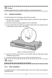
... the supplied rubber feet to support the entire weight of the Switch. Caution: Please unplug the power cord before installing or removing the Switch. 3.2.1 Desktop Installation To install the Switch on the desktop, please follow the steps: 1) Set the Switch on a flat surface strong enough to the recessed areas on the Switch. 3.2.2 Rack Installation To install the Switch in an EIA standard-sized, 19-inch rack, follow the instructions described...
... the supplied rubber feet to support the entire weight of the Switch. Caution: Please unplug the power cord before installing or removing the Switch. 3.2.1 Desktop Installation To install the Switch on the desktop, please follow the steps: 1) Set the Switch on a flat surface strong enough to the recessed areas on the Switch. 3.2.2 Rack Installation To install the Switch in an EIA standard-sized, 19-inch rack, follow the instructions described...
User Guide
Page 10
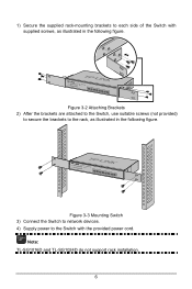
1) Secure the supplied rack-mounting brackets to each side of the Switch with the provided power cord. Note: TL-SG1016D and TL-SG1024D do not support rack installation. 6 Figure 3-3 Mounting Switch 3) Connect the Switch to network devices. 4) Supply power to the rack, as illustrated in the following figure. Figure 3-2 Attaching Brackets 2) After the brackets are attached to the Switch, use suitable screws (not provided) to secure the brackets to the Switch with supplied screws, as illustrated in the following figure.
1) Secure the supplied rack-mounting brackets to each side of the Switch with the provided power cord. Note: TL-SG1016D and TL-SG1024D do not support rack installation. 6 Figure 3-3 Mounting Switch 3) Connect the Switch to network devices. 4) Supply power to the rack, as illustrated in the following figure. Figure 3-2 Attaching Brackets 2) After the brackets are attached to the Switch, use suitable screws (not provided) to secure the brackets to the Switch with supplied screws, as illustrated in the following figure.
User Guide
Page 11
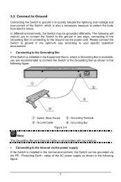
... to quickly release the lightning over-voltage and over-current of the AC power supply as shown in two ways, connecting to the Grounding Bar or connecting to the Ground via the power cord. Figure 3-4 Note: The Grounding Bar and Ground Cable is not provided with our product. • Connecting to the Ground via the power supply If the Switch is installed...
... to quickly release the lightning over-voltage and over-current of the AC power supply as shown in two ways, connecting to the Grounding Bar or connecting to the Ground via the power cord. Figure 3-4 Note: The Grounding Bar and Ground Cable is not provided with our product. • Connecting to the Ground via the power supply If the Switch is installed...
User Guide
Page 12
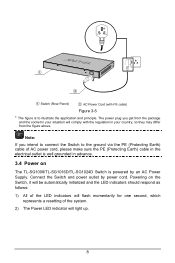
... follows: 1) All of the LED indicators will flash momentarily for one second, which represents a resetting of AC power cord, please make sure the PE (Protecting Earth) cable in the electrical outlet is well grounded in your situation will light up. 8 Figure 3-5 * The figure is powered by power cord. The power plug you intend to connect the Switch to the ground via...
... follows: 1) All of the LED indicators will flash momentarily for one second, which represents a resetting of AC power cord, please make sure the PE (Protecting Earth) cable in the electrical outlet is well grounded in your situation will light up. 8 Figure 3-5 * The figure is powered by power cord. The power plug you intend to connect the Switch to the ground via...
User Guide
Page 13
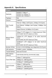
...) Network Media (Cable) 100Base-TX: UTP category 5, 5e cable (maximum 100m) EIA/TIA-568 100 STP (maximum 100m) 1000Base-T: UTP category 5, 5e cable (maximum 100m) EIA/TIA-568 100 STP (maximum 100m) Number of Ports 8/16/24 10/100/1000Mbps Auto-Negotiation RJ-45 ports LED indicators POWER, Link/Act, 1000Mbps Transfer Method Store-and-Forward MAC Address Learning Automatically learning, automatically aging 10Base-T: 14881pps/Port Frame Filter Rate...
...) Network Media (Cable) 100Base-TX: UTP category 5, 5e cable (maximum 100m) EIA/TIA-568 100 STP (maximum 100m) 1000Base-T: UTP category 5, 5e cable (maximum 100m) EIA/TIA-568 100 STP (maximum 100m) Number of Ports 8/16/24 10/100/1000Mbps Auto-Negotiation RJ-45 ports LED indicators POWER, Link/Act, 1000Mbps Transfer Method Store-and-Forward MAC Address Learning Automatically learning, automatically aging 10Base-T: 14881pps/Port Frame Filter Rate...

User Guide
Page 15
... AC power cord connected the Switch with the installation or operation of the TP-LINK TL-SG1008/TL-SG1016D/ TL-SG1024D Switch, please contact us. Appendix C: Contact Information For help with power source properly. ¾ Make sure the power source is turned on and working well. ¾ The cable must be less than 100 meters long(328 feet). E-mail: support@tp-link.com Website: http://www.tp-link.com 11 The Link/Act LED is...
... AC power cord connected the Switch with the installation or operation of the TP-LINK TL-SG1008/TL-SG1016D/ TL-SG1024D Switch, please contact us. Appendix C: Contact Information For help with power source properly. ¾ Make sure the power source is turned on and working well. ¾ The cable must be less than 100 meters long(328 feet). E-mail: support@tp-link.com Website: http://www.tp-link.com 11 The Link/Act LED is...


