Hookup Diagram
Page 1
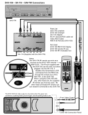
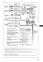
The IR eye supplied with the XAV-7W) Parts List XAV-7W complete DVX-100 Changer XA-118 Adapter RC-91 UniLink/RCA cable set . The DVX-100 front video output is only active when the green wire connects to a parking brake ground trigger, and the parking brake is set Video RCA Cable RM-X120 Remote (DVX...-100) Not Used DVX-100 RM-X130 Display DVX-100 remote IR eye DVX-100 RF modulator box Notes The XAV-7W IR remote eye acts as a receiver for the DVX-100's remote (RM-X120). No other head...
The IR eye supplied with the XAV-7W) Parts List XAV-7W complete DVX-100 Changer XA-118 Adapter RC-91 UniLink/RCA cable set . The DVX-100 front video output is only active when the green wire connects to a parking brake ground trigger, and the parking brake is set Video RCA Cable RM-X120 Remote (DVX...-100) Not Used DVX-100 RM-X130 Display DVX-100 remote IR eye DVX-100 RF modulator box Notes The XAV-7W IR remote eye acts as a receiver for the DVX-100's remote (RM-X120). No other head...
Installation Instructions
Page 5
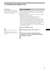
...the LCD may not open up or retract properly. If this angle is close proximity. Be sure to check the cable length and monitor installation conditions. 5 The Media Center main unit and the connection box 1 should be installed within an angle of 25 degrees from horizontal. conditioning outlet,... it . 2 Place the units in their intended mounting locations to verify the following points before installation. Note Keep the units and connection cables apart. Selecting the installation location 1 Set the ignition key to OFF or remove it can also lead to high temperatures and should be ...
...the LCD may not open up or retract properly. If this angle is close proximity. Be sure to check the cable length and monitor installation conditions. 5 The Media Center main unit and the connection box 1 should be installed within an angle of 25 degrees from horizontal. conditioning outlet,... it . 2 Place the units in their intended mounting locations to verify the following points before installation. Note Keep the units and connection cables apart. Selecting the installation location 1 Set the ignition key to OFF or remove it can also lead to high temperatures and should be ...
Installation Instructions
Page 14
...passive speakers. Observe the following leads. Otherwise the cable may damage the unit. • To avoid a malfunction, do not pull the cable when disconnecting the bus cable or other . 14 Note Install the TV antennas away from each other cables. Also see "Connecting Information" on separately available ... ignition key in your dealer. Otherwise, accidental short-circuiting can lead to prevent accidental contact. • Route FM/AM antenna cable, bus cable, RCA interconnects, and power supply leads as far apart from the FM/AM antenna. Using a different fuse or bridging the ...
...passive speakers. Observe the following leads. Otherwise the cable may damage the unit. • To avoid a malfunction, do not pull the cable when disconnecting the bus cable or other . 14 Note Install the TV antennas away from each other cables. Also see "Connecting Information" on separately available ... ignition key in your dealer. Otherwise, accidental short-circuiting can lead to prevent accidental contact. • Route FM/AM antenna cable, bus cable, RCA interconnects, and power supply leads as far apart from the FM/AM antenna. Using a different fuse or bridging the ...
Installation Instructions
Page 15
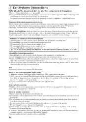
...control lead or power supply lead of antenna booster amplifier*3*5 Light blue (0.25 m) Blue/white (0.25 m) Max. RCA interconnects (optional) Bus cable (5.3 m) (supplied with XT-63V) Front speakers (optional) Amplifiers RCA interconnects (optional) (optional) CONTROL RCA interconnects (5.3 m) (supplied with ...TV tuner unit XAV (optional) XT-63V (optional) White White/black Gray Gray/black Connection box 1 Main unit/ connection box interconnect 3 Rotary Commander RM-X4S (optional) Left Rear speakers (optional) Right Green Green/black Purple Purple/black Media Center main unit ...
...control lead or power supply lead of antenna booster amplifier*3*5 Light blue (0.25 m) Blue/white (0.25 m) Max. RCA interconnects (optional) Bus cable (5.3 m) (supplied with XT-63V) Front speakers (optional) Amplifiers RCA interconnects (optional) (optional) CONTROL RCA interconnects (5.3 m) (supplied with ...TV tuner unit XAV (optional) XT-63V (optional) White White/black Gray Gray/black Connection box 1 Main unit/ connection box interconnect 3 Rotary Commander RM-X4S (optional) Left Rear speakers (optional) Right Green Green/black Purple Purple/black Media Center main unit ...
Operating Instructions (primary manual)
Page 35
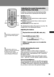
...) SUB (Subwoofer): Subwoofer output level ATT The adjustment procedure is called Source Sound Memory. "ATT••on the display window. Tip When the interface cable of the monitor screen, or the indication "ATT" is connected to make the adjustment. Quickly attenuating the sound Press the ATT button. The example below...
...) SUB (Subwoofer): Subwoofer output level ATT The adjustment procedure is called Source Sound Memory. "ATT••on the display window. Tip When the interface cable of the monitor screen, or the indication "ATT" is connected to make the adjustment. Quickly attenuating the sound Press the ATT button. The example below...
Operating Instructions (primary manual)
Page 39
..., brighter t Color: T less, more than 8 characters long. off : On screen display (OSD) is given in brackets for the display window. on page 41. The video cable, originating from the video source, must be connected to a rear monitor. On the monitor, the name will also scroll. When the selected source is not...
..., brighter t Color: T less, more than 8 characters long. off : On screen display (OSD) is given in brackets for the display window. on page 41. The video cable, originating from the video source, must be connected to a rear monitor. On the monitor, the name will also scroll. When the selected source is not...
Operating Instructions (primary manual)
Page 47
... 39) to "on a metal part of the ignition key. , Press SOURCE. In such a case, contact the Technical Information Center, your dealer, or the nearest Sony service center. Makes noise when the ignition key is connected and you connect the optional equipment. , The cord has been disconnected. "ATT" ...Stored stations and correct time are operated. , The beep sound was disconnected. , Power supply wiring is heard. , Keep antenna cable, bus cable, and audio cables as far away as possible from power supply wiring. Power antenna does not extend. , The power antenna does not have no...
... 39) to "on a metal part of the ignition key. , Press SOURCE. In such a case, contact the Technical Information Center, your dealer, or the nearest Sony service center. Makes noise when the ignition key is connected and you connect the optional equipment. , The cord has been disconnected. "ATT" ...Stored stations and correct time are operated. , The beep sound was disconnected. , Power supply wiring is heard. , Keep antenna cable, bus cable, and audio cables as far away as possible from power supply wiring. Power antenna does not extend. , The power antenna does not have no...

