
Service Manual
Page 4
...Memory and Head Control Circuit 4-12 4-4-11. Gamma Correction and Thermal Storage Correction 4-13 4-4-12. Storage of Order 5-3 5-4. Stair Generation 4-15 4-5-4. Print is Faulty 5-1 5-2. Paper Feeding is Out of Print Count History 4-13 4-5. Feed Operation 6-2 6-4. Control of Order 5-5 5-6. 4-4. Service Mode (Self-diagnostic Function) 6-1 Printing the Test Pattern 6-1 ...15 4-5-3. Troubleshooting 5-1. Door (Opening and Closing) is Out of Order 5-6 6. Head Operation (Up & Down) is Out of Order 5-4 5-5. Semiconductor Pin Assignments 2 UP-895/(E)
...Memory and Head Control Circuit 4-12 4-4-11. Gamma Correction and Thermal Storage Correction 4-13 4-4-12. Storage of Order 5-3 5-4. Stair Generation 4-15 4-5-4. Print is Faulty 5-1 5-2. Paper Feeding is Out of Print Count History 4-13 4-5. Feed Operation 6-2 6-4. Control of Order 5-5 5-6. 4-4. Service Mode (Self-diagnostic Function) 6-1 Printing the Test Pattern 6-1 ...15 4-5-3. Troubleshooting 5-1. Door (Opening and Closing) is Out of Order 5-6 6. Head Operation (Up & Down) is Out of Order 5-4 5-5. Semiconductor Pin Assignments 2 UP-895/(E)

Service Manual
Page 8
... Table of Contents/Overview Table of Parts 35 Front 35 Back 36 Overview Introduction The UP-895/895MD/895CE is a black and white video graphics printer that can load paper just by unplugging the power cord from making any mistakes. The leakage current could void your...31 Specifications 32 Troubleshooting 34 Location and Function of Contents Introduction Overview 21 Prepration Connection 22 Setting Up the Printer 22 Setting the Slide Switches on the Paper Tray..... 22 Setting the DIP Switches on a video monitor. All the equipments connected to radio communications. ...
... Table of Contents/Overview Table of Parts 35 Front 35 Back 36 Overview Introduction The UP-895/895MD/895CE is a black and white video graphics printer that can load paper just by unplugging the power cord from making any mistakes. The leakage current could void your...31 Specifications 32 Troubleshooting 34 Location and Function of Contents Introduction Overview 21 Prepration Connection 22 Setting Up the Printer 22 Setting the Slide Switches on the Paper Tray..... 22 Setting the DIP Switches on a video monitor. All the equipments connected to radio communications. ...

Service Manual
Page 9
...equipment to video output connector Color/black and white video monitor Setting Up the Printer You can set the printer to the desired specifications using two kinds of switches. • Slide switches on the paper tray inside the front door You can set the print mode and other ... the DIP Switches on the Rear Panel To change frequently Setting the Slide Switches on the Paper Tray The factory settings are as follows. 1 2 3 4 5 6 7 8 9 q; 1-3 UP-895/(E) Preparation Connection/Setting Up the Printer Connection Notes • Turn off the power to each tone. COLOR OFF SW-DOWN or ...
...equipment to video output connector Color/black and white video monitor Setting Up the Printer You can set the printer to the desired specifications using two kinds of switches. • Slide switches on the paper tray inside the front door You can set the print mode and other ... the DIP Switches on the Rear Panel To change frequently Setting the Slide Switches on the Paper Tray The factory settings are as follows. 1 2 3 4 5 6 7 8 9 q; 1-3 UP-895/(E) Preparation Connection/Setting Up the Printer Connection Notes • Turn off the power to each tone. COLOR OFF SW-DOWN or ...

Service Manual
Page 10
... when you make more printouts per roll of paper, but less blurred. 5 DIRECTION switch Selects whether the top or bottom of paper, use the UPP-110HA paper as specified for the UP-895/895MD/895CE. When loading paper • Do not fold the paper or touch the printing surface. Also do not...it to ON, and the other bright places. - We recommend storing printouts in memory. Do not leave printouts in helping to save paper by the printer. 9 AGC (Automatic Gain Control) switch Adjusts the input signal to another printed surface. The printout may also cause malfunction of the ...
... when you make more printouts per roll of paper, but less blurred. 5 DIRECTION switch Selects whether the top or bottom of paper, use the UPP-110HA paper as specified for the UP-895/895MD/895CE. When loading paper • Do not fold the paper or touch the printing surface. Also do not...it to ON, and the other bright places. - We recommend storing printouts in memory. Do not leave printouts in helping to save paper by the printer. 9 AGC (Automatic Gain Control) switch Adjusts the input signal to another printed surface. The printout may also cause malfunction of the ...

Service Manual
Page 11
... allow any volatile organic solvent or vinyl chloride to 8 inches) of clay-free paper or polypropylene. - Load the paper. ("Loading Paper" on the video monitor, press the PRINT button. The printer stops printing, captures the new image, and starts printing the new image. If ... paper, then place the paper roll in direct sunlight or other bright places. - The printout may not be printed. 2 Press the OPEN button to feed the paper. 1-5 UP-895/(E) Preparation Loading Paper Loading Paper Notes • Before loading paper, read "Paper" on the printer. In SMALL mode, the printer ...
... allow any volatile organic solvent or vinyl chloride to 8 inches) of clay-free paper or polypropylene. - Load the paper. ("Loading Paper" on the video monitor, press the PRINT button. The printer stops printing, captures the new image, and starts printing the new image. If ... paper, then place the paper roll in direct sunlight or other bright places. - The printout may not be printed. 2 Press the OPEN button to feed the paper. 1-5 UP-895/(E) Preparation Loading Paper Loading Paper Notes • Before loading paper, read "Paper" on the printer. In SMALL mode, the printer ...

Service Manual
Page 13
... contrast and brightness, be properly established. Never pull the cord itself. • Do not disassemble the cabinet. On the printer carriage Do not carry or move the printer when the paper roll is dirty or white stripes appear on the rear panel. Cleaning the cabinet Do not use the... same as the PRINT button, pressing either of image using it has been captured in using the CONTR control. 1-7 UP-895/(E) Operation Printing Adjusting the Contrast and Brightness You can adjust the contrast and brightness of the printer to a wall outlet with a protective earth terminal.
... contrast and brightness, be properly established. Never pull the cord itself. • Do not disassemble the cabinet. On the printer carriage Do not carry or move the printer when the paper roll is dirty or white stripes appear on the rear panel. Cleaning the cabinet Do not use the... same as the PRINT button, pressing either of image using it has been captured in using the CONTR control. 1-7 UP-895/(E) Operation Printing Adjusting the Contrast and Brightness You can adjust the contrast and brightness of the printer to a wall outlet with a protective earth terminal.

Service Manual
Page 14
...the head only when necessary. initiates print. 3 PRINT BUSY (TTL) Goes HIGH during printing. When the buzzer sounds and the printer start ejecting the cleaning sheet, release the FEED button. Supplied accessories Paper roll (UPP-110HG) (1) BNC y BNC connecting cable (1) AC power cord (1) Head cleaning sheet (1) Media label (1) The ... to 60°C (-4°F to 140°F) Storage and transport humidity 20 % to change without notice. 32 Others Specifications Others 33 Others UP-895/(E) 1-8 Others Maintenance/Specifications 4 Close the door by pushing it may cause a malfunction.
...the head only when necessary. initiates print. 3 PRINT BUSY (TTL) Goes HIGH during printing. When the buzzer sounds and the printer start ejecting the cleaning sheet, release the FEED button. Supplied accessories Paper roll (UPP-110HG) (1) BNC y BNC connecting cable (1) AC power cord (1) Head cleaning sheet (1) Media label (1) The ... to 60°C (-4°F to 140°F) Storage and transport humidity 20 % to change without notice. 32 Others Specifications Others 33 Others UP-895/(E) 1-8 Others Maintenance/Specifications 4 Close the door by pushing it may cause a malfunction.

Service Manual
Page 15
...the surface of the paper may result from a cold place to feed paper. Cause/remedy When printing with the thermo-sensitive side up in memory. 0 EMPTY lamp (27) Lights when the printer is too dark or ...895/(E) Others Troubleshooting Troubleshooting The following troubleshooting checks will help you correct the most common problems you may overheat when the printer prints dark image continuously. Before proceeding with your Sony dealer or local authorized Sony service facility. Should the problem persist, unplug the printer and contact your printer. Symptom White specks on ? Paper...
...the surface of the paper may result from a cold place to feed paper. Cause/remedy When printing with the thermo-sensitive side up in memory. 0 EMPTY lamp (27) Lights when the printer is too dark or ...895/(E) Others Troubleshooting Troubleshooting The following troubleshooting checks will help you correct the most common problems you may overheat when the printer prints dark image continuously. Before proceeding with your Sony dealer or local authorized Sony service facility. Should the problem persist, unplug the printer and contact your printer. Symptom White specks on ? Paper...

Service Manual
Page 16
... power input) connector (22) Connect to a wall outlet using the AC power cord supplied with the unit. qs Paper feeder and cutter Cuts the printing paper. Others 36 Others UP-895/(E) For detailed information on slide switches, see the slide switches in the medical environments" on page 20. 2 REMOTE... the door. Also, interrupts printing midway. The output signal type depends on page 22. Back 1 Equipotential terminal (only for use in the paper tray. Refer to "Important safeguards/notice for UP-895MD/ 895CE) Used to connect to the equipotential plug to bring the various parts of a...
... power input) connector (22) Connect to a wall outlet using the AC power cord supplied with the unit. qs Paper feeder and cutter Cuts the printing paper. Others 36 Others UP-895/(E) For detailed information on slide switches, see the slide switches in the medical environments" on page 20. 2 REMOTE... the door. Also, interrupts printing midway. The output signal type depends on page 22. Back 1 Equipotential terminal (only for use in the paper tray. Refer to "Important safeguards/notice for UP-895MD/ 895CE) Used to connect to the equipotential plug to bring the various parts of a...
Service Manual
Page 27
UP-895/(E) 4-1 Image data on the memory is also PWM-converted for image processing and sent to the thermal head. * CLK generator This block generates the operation .... * Memory and head control G/A Print data is converted from analog to frame memory (DRAM). Section 4 Circuit Operation Description Outline The electrical circuit of UP-895 mainly consists of a head, paper, cutter, door, and head temperature. * System control CPU This block supervises and controls each block. The A/D-converted data is fetched to digital.
UP-895/(E) 4-1 Image data on the memory is also PWM-converted for image processing and sent to the thermal head. * CLK generator This block generates the operation .... * Memory and head control G/A Print data is converted from analog to frame memory (DRAM). Section 4 Circuit Operation Description Outline The electrical circuit of UP-895 mainly consists of a head, paper, cutter, door, and head temperature. * System control CPU This block supervises and controls each block. The A/D-converted data is fetched to digital.

Service Manual
Page 28
MA-99 board SE board Sensor Paper Sensor Paper Head Sensor Door Sensor Paper Sensor SE board Platen Motor Fan Motor Head Motor SU board Motor drive motor drive Motor drive Buzzer Selector DIP-SW System control CPU KY board Video circuit A/D D/A Inner SW FRONT PANEL Sensor Paper Front key Video in BNC Video out BNC Memory control IC SD-RAM Board checker EEPROM CLK gene TEMP Thermal head Electrical Block Diagram of UP-895 4-2 UP-895/(E)
MA-99 board SE board Sensor Paper Sensor Paper Head Sensor Door Sensor Paper Sensor SE board Platen Motor Fan Motor Head Motor SU board Motor drive motor drive Motor drive Buzzer Selector DIP-SW System control CPU KY board Video circuit A/D D/A Inner SW FRONT PANEL Sensor Paper Front key Video in BNC Video out BNC Memory control IC SD-RAM Board checker EEPROM CLK gene TEMP Thermal head Electrical Block Diagram of UP-895 4-2 UP-895/(E)

Service Manual
Page 34
... L: STANDARD H: SIDE 0.00 V: SMALL 1.25 V: NORMAL 2.50 V: ZOOM1 3.75 V: ZOOM2 5.00 V: ZOOM1&2 Inner slide switches (S1 through S4) IC304 5pin Function SMOOTH 2pin SHARPNESS 4pin PAPER TYPE 3pin GAMMA Operation L: NORMAL H: HIGH 0.00 V: NORMAL 2.50 V: SOFT 5.00 V: HARD 0.00 V: TYPE I 1.67 V: TYPE II 3.33 V: TYPE III 5.00 V: TYPE IV 0.00 V: TONE...
... L: STANDARD H: SIDE 0.00 V: SMALL 1.25 V: NORMAL 2.50 V: ZOOM1 3.75 V: ZOOM2 5.00 V: ZOOM1&2 Inner slide switches (S1 through S4) IC304 5pin Function SMOOTH 2pin SHARPNESS 4pin PAPER TYPE 3pin GAMMA Operation L: NORMAL H: HIGH 0.00 V: NORMAL 2.50 V: SOFT 5.00 V: HARD 0.00 V: TYPE I 1.67 V: TYPE II 3.33 V: TYPE III 5.00 V: TYPE IV 0.00 V: TONE...
Service Manual
Page 36
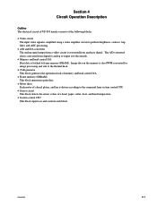
...Operation of head position sensor Position TOP MIDDLE BOTTOM IC304-17pin H L H IC304-16pin H H L Condition Unlocks the door. No paper 4-10 UP-895/(E) The head position is open. 4-4-6. Condition of Door Sensor The door position is detected using optical head position sensors (photo-interrupters PH21 ... sensor Position CLOSE OPEN IC304-20pin L H Condition The door is properly put in the forward and reverse directions. Condition of optical paper sensors (phototransistors PH31 and PH12) and read by a system control (IC304). Lowers the head. Wait (Usual) Print 4-4-5. The ...
...Operation of head position sensor Position TOP MIDDLE BOTTOM IC304-17pin H L H IC304-16pin H H L Condition Unlocks the door. No paper 4-10 UP-895/(E) The head position is open. 4-4-6. Condition of Door Sensor The door position is detected using optical head position sensors (photo-interrupters PH21 ... sensor Position CLOSE OPEN IC304-20pin L H Condition The door is properly put in the forward and reverse directions. Condition of optical paper sensors (phototransistors PH31 and PH12) and read by a system control (IC304). Lowers the head. Wait (Usual) Print 4-4-5. The ...
Service Manual
Page 41
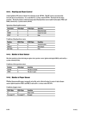
...data generator circuit to the head is also possible to change the darkness by changing the "H" and "L" data input to the latch section. UP-895/(E) 4-15 n The BEO terminal goes from "L" to "H" when starting the print and goes from "H" to "L" when print is controlled by...(64 data) is input to the shift register section in synchronization with the clock output from IC501. Basic Operation Various signals are turned on thermosensitive paper can be changed. This section describes the operation in only one line (nPRINT_PULSE) by the "H" and "L" data in synchronization with a clock. ...
...data generator circuit to the head is also possible to change the darkness by changing the "H" and "L" data input to the latch section. UP-895/(E) 4-15 n The BEO terminal goes from "L" to "H" when starting the print and goes from "H" to "L" when print is controlled by...(64 data) is input to the shift register section in synchronization with the clock output from IC501. Basic Operation Various signals are turned on thermosensitive paper can be changed. This section describes the operation in only one line (nPRINT_PULSE) by the "H" and "L" data in synchronization with a clock. ...
Service Manual
Page 42
... "1" to the head, the 1st stair data is transferred to the latch section and the next 2nd stair data is input to the size of paper. In such a way, the stair data with the heat generated by and stored in a heat generator. (5) Thus, by controlling the STB pulse's T... interval and DR pulse. Correction is an intermediate stair (gray). Therefore, an error occurs in the figure. In this correction circuit. 4-16 UP-895/(E) T64) shown in the energy applied to the shift register. Therefore, this unit, a system control (IC304) measures the temperature change for thermosensitive...
... "1" to the head, the 1st stair data is transferred to the latch section and the next 2nd stair data is input to the size of paper. In such a way, the stair data with the heat generated by and stored in a heat generator. (5) Thus, by controlling the STB pulse's T... interval and DR pulse. Correction is an intermediate stair (gray). Therefore, an error occurs in the figure. In this correction circuit. 4-16 UP-895/(E) T64) shown in the energy applied to the shift register. Therefore, this unit, a system control (IC304) measures the temperature change for thermosensitive...

Service Manual
Page 45
5-3. YES PH31 on SE-531 board or D11 on MA-99 board? UP-895/(E) 5-3 Is signal from sensor available at pin 6 of IC304 on MA-99 board are defective. Pins 18 and 19 of CN3 on SE-532 board is Out of Order START Is signal from sensor available at pin 5 of CN2 on SE-532 board is NO defective. "Paper Sensor" is NO defective. YES LED on front panel or PH12 on MA-99 board?
5-3. YES PH31 on SE-531 board or D11 on MA-99 board? UP-895/(E) 5-3 Is signal from sensor available at pin 6 of IC304 on MA-99 board are defective. Pins 18 and 19 of CN3 on SE-532 board is Out of Order START Is signal from sensor available at pin 5 of CN2 on SE-532 board is NO defective. "Paper Sensor" is NO defective. YES LED on front panel or PH12 on MA-99 board?

Service Manual
Page 47
... Are pulse signals input to bases of Q404 through Q407 on MA-99 board? Peripheral circuits Q404 and Q407, and CN201 on MA-99 board? Paper Feeding is Out of IC301 on NO MA-99 board are defective. YES Pins 22, 23, 24 and 25 of IC301 on MA-99 board...-99 board are NO defective. YES Is signal output from CN8 on MA-99 board is defective. YES Fuse F400 on MA-99 board? UP-895/(E) 5-5 The platen motor is defective. 5-5. YES Are pulse signals input to pins 1, 3, 11 and 13 of Order START Is fuse F400 blown...
... Are pulse signals input to bases of Q404 through Q407 on MA-99 board? Peripheral circuits Q404 and Q407, and CN201 on MA-99 board? Paper Feeding is Out of IC301 on NO MA-99 board are defective. YES Pins 22, 23, 24 and 25 of IC301 on MA-99 board...-99 board are NO defective. YES Is signal output from CN8 on MA-99 board is defective. YES Fuse F400 on MA-99 board? UP-895/(E) 5-5 The platen motor is defective. 5-5. YES Are pulse signals input to pins 1, 3, 11 and 13 of Order START Is fuse F400 blown...
Service Manual
Page 51
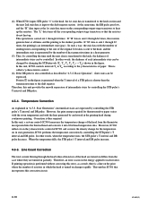
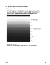
... be displayed in the range of print sheet history Set the PRINT SIZE switch to 150,000. The white line position indicates the sheet of paper. Display and Clearing of Print Sheet History 1 Display of 0 to SML (SMALL mode). Next, press the PRINT key to print the stair step shown in... the white line is in the figure below. 6-4. One step indicates 10,000 sheets of paper that has been printed. UP-895/(E) 6-3 The sheet of print paper exceeding 150,000 is displayed as 150,000. 150,000 sheets of paper (maximum) The sheet of print sheet history In the power off state, turn on...
... be displayed in the range of print sheet history Set the PRINT SIZE switch to 150,000. The white line position indicates the sheet of paper. Display and Clearing of Print Sheet History 1 Display of 0 to SML (SMALL mode). Next, press the PRINT key to print the stair step shown in... the white line is in the figure below. 6-4. One step indicates 10,000 sheets of paper that has been printed. UP-895/(E) 6-3 The sheet of print paper exceeding 150,000 is displayed as 150,000. 150,000 sheets of paper (maximum) The sheet of print sheet history In the power off state, turn on...

Service Manual
Page 57
... o SHAFT,HEAD FULCRUM 114 3-624-816-01 s STOPPER,ROLL 115 4-926-219-02 s RING (DIA.2.3), RETAINING UP-895/(E) 8-3 Part No. SP Description 101 A-8323-915-A o MOUNTED CIRCUIT BOARD, KY-454 102 X-3605-752-1 o ASSY,PAPER TRAY 103 1-251-855-11 s HEAD, THERMAL (LVE6413SS) 104 1-763-007-21 o FAN, DC (OPTION) 105 1-792...
... o SHAFT,HEAD FULCRUM 114 3-624-816-01 s STOPPER,ROLL 115 4-926-219-02 s RING (DIA.2.3), RETAINING UP-895/(E) 8-3 Part No. SP Description 101 A-8323-915-A o MOUNTED CIRCUIT BOARD, KY-454 102 X-3605-752-1 o ASSY,PAPER TRAY 103 1-251-855-11 s HEAD, THERMAL (LVE6413SS) 104 1-763-007-21 o FAN, DC (OPTION) 105 1-792...
Service Manual
Page 59
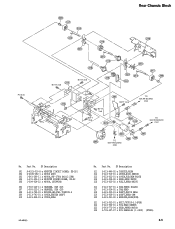
...-11 o HARNESS, SUB (2P) 308 3-613-740-01 s SPRING,HELICAL TORSION A 309 3-613-781-01 s COVER,CENTER SHAFT 310 3-623-868-01 o COVER,GEAR UP-895/(E) No. Part No. SP Description 311 3-623-886-02 o CHASSIS,REAR 312 3-623-910-01 s LEVER,DOOR SENSOR 313 3-623-922-01 o COVER,FULCRUM PLATE... 3-623-931-02 s BEARING,REAR(POM) 321 3-623-932-01 s BELT,70TN10-3.5(PUR) 322 3-623-933-01 s FIN,HEAD SENSOR 323 3-683-773-04 s GEAR,PAPER MOTOR 324 3-703-357-07 s PIN PARALLEL (1.6X10) (STEEL) 8-5 PS 3x6 Rear Chassis Block 309 317 319 324 310 316 320 311 BVTT 3x6 318...
...-11 o HARNESS, SUB (2P) 308 3-613-740-01 s SPRING,HELICAL TORSION A 309 3-613-781-01 s COVER,CENTER SHAFT 310 3-623-868-01 o COVER,GEAR UP-895/(E) No. Part No. SP Description 311 3-623-886-02 o CHASSIS,REAR 312 3-623-910-01 s LEVER,DOOR SENSOR 313 3-623-922-01 o COVER,FULCRUM PLATE... 3-623-931-02 s BEARING,REAR(POM) 321 3-623-932-01 s BELT,70TN10-3.5(PUR) 322 3-623-933-01 s FIN,HEAD SENSOR 323 3-683-773-04 s GEAR,PAPER MOTOR 324 3-703-357-07 s PIN PARALLEL (1.6X10) (STEEL) 8-5 PS 3x6 Rear Chassis Block 309 317 319 324 310 316 320 311 BVTT 3x6 318...
