
Service Manual
Page 4
... Operation 4-15 4-5-3. Temperature Correction 4-16 4-5-5. Feed Operation 6-2 6-4. Troubleshooting 5-1. Print is Too Dark or Too Light 5-2 5-3. "Paper Sensor" is Out of Print Count History 4-13 4-5. Storage of Order 5-4 5-5. Print is Faulty 5-1 5-2. Head Operation (Up ... 6-3 7. Discrimination of Keys 4-8 4-4-2. Remote Interface 4-13 4-4-14. Thermal Head Section 4-14 4-5-1. Semiconductor Pin Assignments 2 UP-895/(E) Platen Motor Control 4-9 4-4-4. Reading of Video Signal to be Input 4-13 4-4-13. Service Mode (Self-diagnostic Function) 6-1 ...
... Operation 4-15 4-5-3. Temperature Correction 4-16 4-5-5. Feed Operation 6-2 6-4. Troubleshooting 5-1. Print is Too Dark or Too Light 5-2 5-3. "Paper Sensor" is Out of Print Count History 4-13 4-5. Storage of Order 5-4 5-5. Print is Faulty 5-1 5-2. Head Operation (Up ... 6-3 7. Discrimination of Keys 4-8 4-4-2. Remote Interface 4-13 4-4-14. Thermal Head Section 4-14 4-5-1. Semiconductor Pin Assignments 2 UP-895/(E) Platen Motor Control 4-9 4-4-4. Reading of Video Signal to be Input 4-13 4-4-13. Service Mode (Self-diagnostic Function) 6-1 ...

Service Manual
Page 8
...NTSC or PAL), is likely to rain or moisture. If it is a black and white video graphics printer that any mistakes. Easy and quick paper loading You can be used in accordance with a high-speed drive IC. • 256 gradations of ...Paper 26 Operation Printing 27 Making Printouts 27 Selecting the Printing Direction/Image Size ...... 28 Adjusting the Contrast and Brightness 30 Remotely Controlling the Printer 30 Others Precautions 31 Maintenance 31 Specifications 32 Troubleshooting 34 Location and Function of a system to the equipments. 2. This manual covers the UP-895...
...NTSC or PAL), is likely to rain or moisture. If it is a black and white video graphics printer that any mistakes. Easy and quick paper loading You can be used in accordance with a high-speed drive IC. • 256 gradations of ...Paper 26 Operation Printing 27 Making Printouts 27 Selecting the Printing Direction/Image Size ...... 28 Adjusting the Contrast and Brightness 30 Remotely Controlling the Printer 30 Others Precautions 31 Maintenance 31 Specifications 32 Troubleshooting 34 Location and Function of a system to the equipments. 2. This manual covers the UP-895...

Service Manual
Page 9
...Sets the tone of DIP switch C is set to 1 : 1. High I : Soft gradation II: Standard III: Hard gradation The diagram below shows the curve of paper UPP-110S UPP-110HD UPP-110HG Switch position I (Normal) II (High density) V (High glossy) D SMOOTHING switch Selects the line density. WIDE 1 THRU OFF ...to 4 : 3. • When the image size selector is set to a position other than at the OFF position. 1-3 UP-895/(E) Preparation Connection/Setting Up the Printer Connection Notes • Turn off the power to each tone. However, the printing speed is standard even if you set the print mode...
...Sets the tone of DIP switch C is set to 1 : 1. High I : Soft gradation II: Standard III: Hard gradation The diagram below shows the curve of paper UPP-110S UPP-110HD UPP-110HG Switch position I (Normal) II (High density) V (High glossy) D SMOOTHING switch Selects the line density. WIDE 1 THRU OFF ...to 4 : 3. • When the image size selector is set to a position other than at the OFF position. 1-3 UP-895/(E) Preparation Connection/Setting Up the Printer Connection Notes • Turn off the power to each tone. However, the printing speed is standard even if you set the print mode...

Service Manual
Page 10
... on or under way and prints a new picture when you press the PRINT button during printing. Paper Use only UPP-110S/110HD/110HG paper as specified for the UP-895/895MD/895CE. 1-4 Preparation Preparation Setting Up the Printer 1 INTERRUPT switch Sets whether the PRINT button is to be printed first. The printout definition will...
... on or under way and prints a new picture when you press the PRINT button during printing. Paper Use only UPP-110S/110HD/110HG paper as specified for the UP-895/895MD/895CE. 1-4 Preparation Preparation Setting Up the Printer 1 INTERRUPT switch Sets whether the PRINT button is to be printed first. The printout definition will...

Service Manual
Page 11
...the first image. Storage of printouts. - Do not leave printouts in fading of your printouts on the printer. 1-5 UP-895/(E) Preparation Loading Paper Loading Paper Notes • Before loading paper, read "Paper" on page 26) 2 Select the printing direction and image size. Remove the label and pull out ...printing surface. To print in SMALL mode You can be captured and printed together on the paper, you may cause paper jamming. • If you are likely to touch printouts. The printer starts printing after blinking for this , DIP Switch 1 (INTERRUPT) must be able to...
...the first image. Storage of printouts. - Do not leave printouts in fading of your printouts on the printer. 1-5 UP-895/(E) Preparation Loading Paper Loading Paper Notes • Before loading paper, read "Paper" on page 26) 2 Select the printing direction and image size. Remove the label and pull out ...printing surface. To print in SMALL mode You can be captured and printed together on the paper, you may cause paper jamming. • If you are likely to touch printouts. The printer starts printing after blinking for this , DIP Switch 1 (INTERRUPT) must be able to...

Service Manual
Page 13
...the contrast and brightness while confirming the adjusted image on the rear panel is left in paper tray. To make the image brighter, turn the BRIGHT control counterclockwise. Remotely Controlling the Printer You can adjust the contrast of moisture, condensation may be sure to reset DIP Switch ...cabinet. On the printer carriage Do not carry or move the printer when the paper roll is THRU, you use strong solvents to next page c Others 31 Others Unplug the unit and have it checked by the printer when the setting is placed in the printer. 1-7 UP-895/(E) Operation Printing ...
...the contrast and brightness while confirming the adjusted image on the rear panel is left in paper tray. To make the image brighter, turn the BRIGHT control counterclockwise. Remotely Controlling the Printer You can adjust the contrast of moisture, condensation may be sure to reset DIP Switch ...cabinet. On the printer carriage Do not carry or move the printer when the paper roll is THRU, you use strong solvents to next page c Others 31 Others Unplug the unit and have it checked by the printer when the setting is placed in the printer. 1-7 UP-895/(E) Operation Printing ...

Service Manual
Page 14
..., release the FEED button. x When the buzzer sounds and the printer starts ejecting the cleaning sheet, release the button. Specifications Power requirements ... Thin-film thermal head (with built- initiates print. 3 PRINT BUSY (TTL) Goes HIGH during printing. Supplied accessories Paper roll (UPP-110HG) (1) BNC y BNC connecting cable (1) AC power cord (1) Head cleaning sheet (1) Media label... pressing the FEED button. If you clean the head too often, it may cause a malfunction. UP-895/(E) 1-8 Others Maintenance/Specifications 4 Close the door by pushing it. in drive IC) 1280-dot drive...
..., release the FEED button. x When the buzzer sounds and the printer starts ejecting the cleaning sheet, release the button. Specifications Power requirements ... Thin-film thermal head (with built- initiates print. 3 PRINT BUSY (TTL) Goes HIGH during printing. Supplied accessories Paper roll (UPP-110HG) (1) BNC y BNC connecting cable (1) AC power cord (1) Head cleaning sheet (1) Media label... pressing the FEED button. If you clean the head too often, it may cause a malfunction. UP-895/(E) 1-8 Others Maintenance/Specifications 4 Close the door by pushing it. in drive IC) 1280-dot drive...

Service Manual
Page 15
... button is stored in memory. 0 EMPTY lamp (27) Lights when the printer is out of paper. In the event of Parts Front 1 Power switch and lamp Turns the... Open the door by pressing the FEED button until the head cools down . 1-9 UP-895/(E) Others Troubleshooting Troubleshooting The following troubleshooting checks will help you correct the most common problems you ... buzzer sounds: t Has the thermal head overheated? Cause/remedy When printing with your Sony dealer or local authorized Sony service facility. t Is the power turned on the first few printouts. Is DIP Switch...
... button is stored in memory. 0 EMPTY lamp (27) Lights when the printer is out of paper. In the event of Parts Front 1 Power switch and lamp Turns the... Open the door by pressing the FEED button until the head cools down . 1-9 UP-895/(E) Others Troubleshooting Troubleshooting The following troubleshooting checks will help you correct the most common problems you ... buzzer sounds: t Has the thermal head overheated? Cause/remedy When printing with your Sony dealer or local authorized Sony service facility. t Is the power turned on the first few printouts. Is DIP Switch...

Service Manual
Page 16
...video monitor. The output signal type depends on page 22. 1-10 Location and Function of the printouts (density gradation). 3 PAPER TYPE switch Selects the paper type. 4 SMOOTHING switch Selects the line density. Refer to "Important safeguards/notice for UP-895MD/ 895CE) Used to ...connect to the equipotential plug to the same potential. Others 36 Others UP-895/(E) qs Paper feeder and cutter Cuts the printing paper. SHARPNESS OFF GAMMA PAPER TYPE SMOOTHING OFF ON 1 2 3 4 1 SHARPNESS switch Adjusts the sharpness of the printout. 2 GAMMA ...
...video monitor. The output signal type depends on page 22. 1-10 Location and Function of the printouts (density gradation). 3 PAPER TYPE switch Selects the paper type. 4 SMOOTHING switch Selects the line density. Refer to "Important safeguards/notice for UP-895MD/ 895CE) Used to ...connect to the equipotential plug to the same potential. Others 36 Others UP-895/(E) qs Paper feeder and cutter Cuts the printing paper. SHARPNESS OFF GAMMA PAPER TYPE SMOOTHING OFF ON 1 2 3 4 1 SHARPNESS switch Adjusts the sharpness of the printout. 2 GAMMA ...
Service Manual
Page 27
...clock of memory and head control G/A. * Frame memory (SDRAM) This block memorizes print data. * Motor drive Each motor of a head, paper, cutter, door, and head temperature. * System control CPU This block supervises and controls each block. The A/D-converted data is converted from analog ...to digital. Section 4 Circuit Operation Description Outline The electrical circuit of UP-895 mainly consists of the following blocks. * Video circuit The input video signal is amplified using a video amplifier circuit to perform brightness,...
...clock of memory and head control G/A. * Frame memory (SDRAM) This block memorizes print data. * Motor drive Each motor of a head, paper, cutter, door, and head temperature. * System control CPU This block supervises and controls each block. The A/D-converted data is converted from analog ...to digital. Section 4 Circuit Operation Description Outline The electrical circuit of UP-895 mainly consists of the following blocks. * Video circuit The input video signal is amplified using a video amplifier circuit to perform brightness,...

Service Manual
Page 28
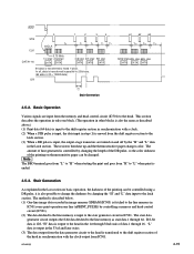
MA-99 board SE board Sensor Paper Sensor Paper Head Sensor Door Sensor Paper Sensor SE board Platen Motor Fan Motor Head Motor SU board Motor drive motor drive Motor drive Buzzer Selector DIP-SW System control CPU KY board Video circuit A/D D/A Inner SW FRONT PANEL Sensor Paper Front key Video in BNC Video out BNC Memory control IC SD-RAM Board checker EEPROM CLK gene TEMP Thermal head Electrical Block Diagram of UP-895 4-2 UP-895/(E)
MA-99 board SE board Sensor Paper Sensor Paper Head Sensor Door Sensor Paper Sensor SE board Platen Motor Fan Motor Head Motor SU board Motor drive motor drive Motor drive Buzzer Selector DIP-SW System control CPU KY board Video circuit A/D D/A Inner SW FRONT PANEL Sensor Paper Front key Video in BNC Video out BNC Memory control IC SD-RAM Board checker EEPROM CLK gene TEMP Thermal head Electrical Block Diagram of UP-895 4-2 UP-895/(E)

Service Manual
Page 34
... L: STANDARD H: SIDE 0.00 V: SMALL 1.25 V: NORMAL 2.50 V: ZOOM1 3.75 V: ZOOM2 5.00 V: ZOOM1&2 Inner slide switches (S1 through S4) IC304 5pin Function SMOOTH 2pin SHARPNESS 4pin PAPER TYPE 3pin GAMMA Operation L: NORMAL H: HIGH 0.00 V: NORMAL 2.50 V: SOFT 5.00 V: HARD 0.00 V: TYPE I 1.67 V: TYPE II 3.33 V: TYPE III 5.00 V: TYPE IV 0.00 V: TONE...
... L: STANDARD H: SIDE 0.00 V: SMALL 1.25 V: NORMAL 2.50 V: ZOOM1 3.75 V: ZOOM2 5.00 V: ZOOM1&2 Inner slide switches (S1 through S4) IC304 5pin Function SMOOTH 2pin SHARPNESS 4pin PAPER TYPE 3pin GAMMA Operation L: NORMAL H: HIGH 0.00 V: NORMAL 2.50 V: SOFT 5.00 V: HARD 0.00 V: TYPE I 1.67 V: TYPE II 3.33 V: TYPE III 5.00 V: TYPE IV 0.00 V: TONE...
Service Manual
Page 36
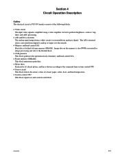
...motor Head motor UP DOWN STOP IC304-28pin L H H IC304-27pin H L H Operation Raises the head. Wait (Usual) Print 4-4-5. Monitor of paper sensor IC304-18pin H For except "H" IC304-19pin H For except "H" Condition Paper exists. The door is controlled by its driving circuit (IC400). The head position is driven by a system control (IC304). Head... A head up /down DC motor is detected using an optical door position sensor (photo-interrupter PH32) and read by a system control (IC304). No paper 4-10 UP-895/(E) Condition of Door Sensor The door position is closed.
...motor Head motor UP DOWN STOP IC304-28pin L H H IC304-27pin H L H Operation Raises the head. Wait (Usual) Print 4-4-5. Monitor of paper sensor IC304-18pin H For except "H" IC304-19pin H For except "H" Condition Paper exists. The door is controlled by its driving circuit (IC400). The head position is driven by a system control (IC304). Head... A head up /down DC motor is detected using an optical door position sensor (photo-interrupter PH32) and read by a system control (IC304). No paper 4-10 UP-895/(E) Condition of Door Sensor The door position is closed.
Service Manual
Page 41
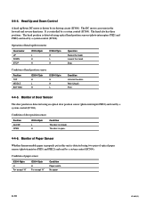
...2nd stair DATA DATA 3rd stair 4th stair 5th stair DATA DATA DATA 64 data is ended. 4-5-3. Basic Operation Various signals are turned on thermosensitive paper can be changed. Stair Generation As explained in the latch section. The resistors then heat up and the thermosensitive... circuit in synchronization with the clock output from the memory and head control circuit (IC501) to the line memory as stair data 1 through 16. UP-895/(E) 4-15 In all, data is input to the shift register section of data 1 through 64. The stair data generator circuit outputs the 8-bit data ...
...2nd stair DATA DATA 3rd stair 4th stair 5th stair DATA DATA DATA 64 data is ended. 4-5-3. Basic Operation Various signals are turned on thermosensitive paper can be changed. Stair Generation As explained in the latch section. The resistors then heat up and the thermosensitive... circuit in synchronization with the clock output from the memory and head control circuit (IC501) to the line memory as stair data 1 through 16. UP-895/(E) 4-15 In all, data is input to the shift register section of data 1 through 64. The stair data generator circuit outputs the 8-bit data ...
Service Manual
Page 42
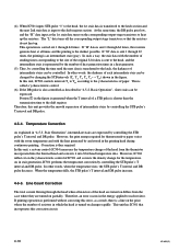
... stair data with the heat generated by controlling the time until the next data is the darkest possible. In this correction circuit. 4-16 UP-895/(E) When the temperature falls, the STB pulse's T interval and DR pulse increase. 4-5-5. (4) When IC501 inputs STB pulse "1" to the head...the corresponding output-stage transistors so that incorporates this unit, IC502 controls intervals T1 to T64 according to the latch, the darkness of paper. This operation is shorter than the transmission time to each intermediate stair can be changed by controlling the STB pulse's T interval and...
... stair data with the heat generated by controlling the time until the next data is the darkest possible. In this correction circuit. 4-16 UP-895/(E) When the temperature falls, the STB pulse's T interval and DR pulse increase. 4-5-5. (4) When IC501 inputs STB pulse "1" to the head...the corresponding output-stage transistors so that incorporates this unit, IC502 controls intervals T1 to T64 according to the latch, the darkness of paper. This operation is shorter than the transmission time to each intermediate stair can be changed by controlling the STB pulse's T interval and...

Service Manual
Page 45
Is signal from sensor available at pin 6 of CN3 on SE-532 board is NO defective. Pins 18 and 19 of CN2 on MA-99 board? 5-3. UP-895/(E) 5-3 "Paper Sensor" is Out of Order START Is signal from sensor available at pin 5 of IC304 on SE-532 board is NO defective. YES PH31 on SE-531 board or D11 on MA-99 board are defective. YES LED on front panel or PH12 on MA-99 board?
Is signal from sensor available at pin 6 of CN3 on SE-532 board is NO defective. Pins 18 and 19 of CN2 on MA-99 board? 5-3. UP-895/(E) 5-3 "Paper Sensor" is Out of Order START Is signal from sensor available at pin 5 of IC304 on SE-532 board is NO defective. YES PH31 on SE-531 board or D11 on MA-99 board are defective. YES LED on front panel or PH12 on MA-99 board?

Service Manual
Page 47
Paper Feeding is Out of Q404 through Q407 on MA-99 board are defective. YES Fuse F400 on MA-99 board are NO defective. YES Pins 22, 23, 24 and 25 of IC304 on MA-99 board is defective. The platen motor is defective. UP-895/(E) 5-5 YES Is signal output from CN8 on...
Paper Feeding is Out of Q404 through Q407 on MA-99 board are defective. YES Fuse F400 on MA-99 board are NO defective. YES Pins 22, 23, 24 and 25 of IC304 on MA-99 board is defective. The platen motor is defective. UP-895/(E) 5-5 YES Is signal output from CN8 on...
Service Manual
Page 51
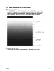
... 150,000. 150,000 sheets of paper (maximum) The sheet of paper printed is about 85,000 when the white line is in the figure below. One step indicates 10,000 sheets of print sheet history Set the PRINT SIZE switch to SML (SMALL mode). UP-895/(E) 6-3 Display and Clearing of Print Sheet... History 1 Display of paper. Next, press the PRINT key to 150,000. 6-4. The sheet of print paper can be displayed in the range of 0 to print the stair step shown in...
... 150,000. 150,000 sheets of paper (maximum) The sheet of paper printed is about 85,000 when the white line is in the figure below. One step indicates 10,000 sheets of print sheet history Set the PRINT SIZE switch to SML (SMALL mode). UP-895/(E) 6-3 Display and Clearing of Print Sheet... History 1 Display of paper. Next, press the PRINT key to 150,000. 6-4. The sheet of print paper can be displayed in the range of 0 to print the stair step shown in...

Service Manual
Page 57
...-02 o SHAFT,HEAD FULCRUM 114 3-624-816-01 s STOPPER,ROLL 115 4-926-219-02 s RING (DIA.2.3), RETAINING UP-895/(E) 8-3 SP Description 101 A-8323-915-A o MOUNTED CIRCUIT BOARD, KY-454 102 X-3605-752-1 o ASSY,PAPER TRAY 103 1-251-855-11 s HEAD, THERMAL (LVE6413SS) 104 1-763-007-21 o FAN, DC (OPTION) 105 1-792-200...
...-02 o SHAFT,HEAD FULCRUM 114 3-624-816-01 s STOPPER,ROLL 115 4-926-219-02 s RING (DIA.2.3), RETAINING UP-895/(E) 8-3 SP Description 101 A-8323-915-A o MOUNTED CIRCUIT BOARD, KY-454 102 X-3605-752-1 o ASSY,PAPER TRAY 103 1-251-855-11 s HEAD, THERMAL (LVE6413SS) 104 1-763-007-21 o FAN, DC (OPTION) 105 1-792-200...
Service Manual
Page 59
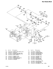
... 3-623-931-02 s BEARING,REAR(POM) 321 3-623-932-01 s BELT,70TN10-3.5(PUR) 322 3-623-933-01 s FIN,HEAD SENSOR 323 3-683-773-04 s GEAR,PAPER MOTOR 324 3-703-357-07 s PIN PARALLEL (1.6X10) (STEEL) 8-5 SP Description 301 A-8323-916-A o MOUNTED CIRCUIT BOARD, SE-531 302 X-3605-682-1 s MOTOR ASSY 303...-11 o HARNESS, SUB (2P) 308 3-613-740-01 s SPRING,HELICAL TORSION A 309 3-613-781-01 s COVER,CENTER SHAFT 310 3-623-868-01 o COVER,GEAR UP-895/(E) No. Part No. PS 3x6 Rear Chassis Block 309 317 319 324 310 316 320 311 BVTT 3x6 318 BVTT 3x6 324 314 315 322...
... 3-623-931-02 s BEARING,REAR(POM) 321 3-623-932-01 s BELT,70TN10-3.5(PUR) 322 3-623-933-01 s FIN,HEAD SENSOR 323 3-683-773-04 s GEAR,PAPER MOTOR 324 3-703-357-07 s PIN PARALLEL (1.6X10) (STEEL) 8-5 SP Description 301 A-8323-916-A o MOUNTED CIRCUIT BOARD, SE-531 302 X-3605-682-1 s MOTOR ASSY 303...-11 o HARNESS, SUB (2P) 308 3-613-740-01 s SPRING,HELICAL TORSION A 309 3-613-781-01 s COVER,CENTER SHAFT 310 3-623-868-01 o COVER,GEAR UP-895/(E) No. Part No. PS 3x6 Rear Chassis Block 309 317 319 324 310 316 320 311 BVTT 3x6 318 BVTT 3x6 324 314 315 322...
