
Service Manual
Page 1
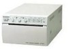
VIDEO GRAPHIC PRINTER UP-895 UP-895CE UP-895MD SERVICE MANUAL 1st Edition
VIDEO GRAPHIC PRINTER UP-895 UP-895CE UP-895MD SERVICE MANUAL 1st Edition

Service Manual
Page 3
... of Fan Motor 2-6 3. Initialization of Contents 1. AGC Circuit 4-3 4-1-4. Memory and Head Control Circuit 4-4 4-3-1. Operating Instructions 2. Service Information 2-1. Thermal Head Control and One-Line Memory 4-5 UP-895/(E) 1 Video Circuit 4-3 4-1-1. Table of Print Count History 3-3 4. AGC Adjustment 3-1 3-2.
... of Fan Motor 2-6 3. Initialization of Contents 1. AGC Circuit 4-3 4-1-4. Memory and Head Control Circuit 4-4 4-3-1. Operating Instructions 2. Service Information 2-1. Thermal Head Control and One-Line Memory 4-5 UP-895/(E) 1 Video Circuit 4-3 4-1-1. Table of Print Count History 3-3 4. AGC Adjustment 3-1 3-2.

Service Manual
Page 4
... 5-3 5-4. Feed Operation 6-2 6-4. Service Mode (Self-diagnostic Function) 6-1 Printing the Test Pattern 6-1 6-2. Print is Out of Order 5-4 5-5. Monitor of Paper Sensor 4-10 4-4-7. Semiconductor Pin Assignments 2 UP-895/(E) Head Up and Down Control 4-10 4-4-5. Monitor of Door Sensor 4-10 4-4-6. Remote Interface 4-13 4-4-14. Line Count Correction 4-16 5. "Paper Sensor" is Faulty 5-1 5-2.
... 5-3 5-4. Feed Operation 6-2 6-4. Service Mode (Self-diagnostic Function) 6-1 Printing the Test Pattern 6-1 6-2. Print is Out of Order 5-4 5-5. Monitor of Paper Sensor 4-10 4-4-7. Semiconductor Pin Assignments 2 UP-895/(E) Head Up and Down Control 4-10 4-4-5. Monitor of Door Sensor 4-10 4-4-6. Remote Interface 4-13 4-4-14. Line Count Correction 4-16 5. "Paper Sensor" is Faulty 5-1 5-2.

Service Manual
Page 5
Spare Parts 8-1. Electrical Parts List 8-7 9. 8. Notes on Repair Parts 8-1 8-2. Block Diagram Overall ...9-1 10. Schematic Diagrams and Board Layouts FRAME ...10-2 KY-454 ...10-2 SE-531 ...10-2 SE-532 ...10-2 SU-52 ...10-2 MA-99 ...10-4 UP-895/(E) 3 Exploded Views 8-2 8-3.
Spare Parts 8-1. Electrical Parts List 8-7 9. 8. Notes on Repair Parts 8-1 8-2. Block Diagram Overall ...9-1 10. Schematic Diagrams and Board Layouts FRAME ...10-2 KY-454 ...10-2 SE-531 ...10-2 SE-532 ...10-2 SU-52 ...10-2 MA-99 ...10-4 UP-895/(E) 3 Exploded Views 8-2 8-3.

Service Manual
Page 7
UP-895/(E) 3-868-286-01 (1) Video Graphic Printer Instructions for Use Page 20 GB Section 1 Operating Instructions This section is extracted from operation manual. (For UP-895MD/895CE) UP-895 UP-895MD UP-895CE © 1999 Sony Corporation 1-1
UP-895/(E) 3-868-286-01 (1) Video Graphic Printer Instructions for Use Page 20 GB Section 1 Operating Instructions This section is extracted from operation manual. (For UP-895MD/895CE) UP-895 UP-895MD UP-895CE © 1999 Sony Corporation 1-1

Service Manual
Page 8
...harmful interference in this equipment. Refer servicing to comply with FCC emission limits. This manual covers the UP-895/895MD/895CE models. DIP switches and slide switches to optimize the printer • You can adjust printout quality and select the paper type by setting the slide switches. •...to Part 15 of this equipment in a residential area is a black and white video graphics printer that any other equipment in a commercial environment. For the customers in the U.S.A. (for UP-895/895MD) This equipment has been tested and found to comply with the limits for UP-895MD)...
...harmful interference in this equipment. Refer servicing to comply with FCC emission limits. This manual covers the UP-895/895MD/895CE models. DIP switches and slide switches to optimize the printer • You can adjust printout quality and select the paper type by setting the slide switches. •...to Part 15 of this equipment in a residential area is a black and white video graphics printer that any other equipment in a commercial environment. For the customers in the U.S.A. (for UP-895/895MD) This equipment has been tested and found to comply with the limits for UP-895MD)...

Service Manual
Page 9
... To make a sharper outline, set to 1 : 1. However, the printing speed is set the switch to the proper position. 1-3 UP-895/(E) Preparation Connection/Setting Up the Printer Connection Notes • Turn off the power to each tone. OFF: Normally keep this switch to emphasize an outline of the paper type...1:1 FIELD REV WIDE 2 NORM EE ON - Video equipment to video output connector Color/black and white video monitor Setting Up the Printer You can set the printer to the desired specifications using two kinds of switches. • Slide switches on the rear panel is set to 4 : 3. ...
... To make a sharper outline, set to 1 : 1. However, the printing speed is set the switch to the proper position. 1-3 UP-895/(E) Preparation Connection/Setting Up the Printer Connection Notes • Turn off the power to each tone. OFF: Normally keep this switch to emphasize an outline of the paper type...1:1 FIELD REV WIDE 2 NORM EE ON - Video equipment to video output connector Color/black and white video monitor Setting Up the Printer You can set the printer to the desired specifications using two kinds of switches. • Slide switches on the rear panel is set to 4 : 3. ...

Service Manual
Page 10
...75 Ω ON/OFF switch ON (SW-DOWN): When nothing is selected regardless of the setting of the printer. Paper Use only UPP-110S/110HD/110HG paper as specified for the UP-895/895MD/895CE. Alcohol, plastic tape or film will be printed is progressively widened in the OFF mode, the ... way. You cannot use double-sided adhesive tape or water-based glue. 24 Preparation Preparation 25 UP-895/(E) WIDE 1 (Switch 7, SW-DOWN position): Prints when the signal scans beyond the edge of the printers to ON, and the other video equipment is pressed during printing in the NORM, WIDE 1, and ...
...75 Ω ON/OFF switch ON (SW-DOWN): When nothing is selected regardless of the setting of the printer. Paper Use only UPP-110S/110HD/110HG paper as specified for the UP-895/895MD/895CE. Alcohol, plastic tape or film will be printed is progressively widened in the OFF mode, the ... way. You cannot use double-sided adhesive tape or water-based glue. 24 Preparation Preparation 25 UP-895/(E) WIDE 1 (Switch 7, SW-DOWN position): Prints when the signal scans beyond the edge of the printers to ON, and the other video equipment is pressed during printing in the NORM, WIDE 1, and ...

Service Manual
Page 11
...on or under a diazo copy sheet. Do not pull out the paper manually. 26 Preparation Printing Before making printouts Confirm the following . Should this printer. (page 25) • Set the PAPER TYPE switch according to the paper type. (page 23) Loading 1 Press the power switch to 8... inches) of clay-free paper or polypropylene. - Do not allow any volatile organic solvent or vinyl chloride to feed the paper. 1-5 UP-895/(E) Preparation Loading Paper Loading Paper Notes • Before loading paper, read "Paper" on page 26) 2 Select the printing direction and image size....
...on or under a diazo copy sheet. Do not pull out the paper manually. 26 Preparation Printing Before making printouts Confirm the following . Should this printer. (page 25) • Set the PAPER TYPE switch according to the paper type. (page 23) Loading 1 Press the power switch to 8... inches) of clay-free paper or polypropylene. - Do not allow any volatile organic solvent or vinyl chloride to feed the paper. 1-5 UP-895/(E) Preparation Loading Paper Loading Paper Notes • Before loading paper, read "Paper" on page 26) 2 Select the printing direction and image size....

Service Manual
Page 12
... button. To print in the same direction as nothing is retained in the direction where the image is available. To print the image in the printer's memory until you press the COPY button, a short buzzer sounds. Negative printouts You can make multiple copies of the video image on the video...in different directions and sizes except in normal or small size by 90 degrees counterclockwise, set the selector to STD (standard). Operation 29 UP-895/(E) STD SIDE STD SIDE Image displayed on the monitor after turning the power on the front panel to the combination of settings of the STD...
... button. To print in the same direction as nothing is retained in the direction where the image is available. To print the image in the printer's memory until you press the COPY button, a short buzzer sounds. Negative printouts You can make multiple copies of the video image on the video...in different directions and sizes except in normal or small size by 90 degrees counterclockwise, set the selector to STD (standard). Operation 29 UP-895/(E) STD SIDE STD SIDE Image displayed on the monitor after turning the power on the front panel to the combination of settings of the STD...

Service Manual
Page 13
...moved from a cold room to a warm room or when it checked by grasping the plug. Avoid locations near heat sources. 1-7 UP-895/(E) Operation Printing Adjusting the Contrast and Brightness You can adjust the contrast and brightness of moisture, condensation may cause a malfunction. Since the ...monitor without being captured and immediately printed when DIP Switch 1 (INTERRUPT) on the rear panel is dirty or white stripes appear on the printer. 2 Press the OPEN button to EE (SW-UP). To make the contrast stronger, turn the CONTR control counterclockwise. 30 Operation Precautions...
...moved from a cold room to a warm room or when it checked by grasping the plug. Avoid locations near heat sources. 1-7 UP-895/(E) Operation Printing Adjusting the Contrast and Brightness You can adjust the contrast and brightness of moisture, condensation may cause a malfunction. Since the ...monitor without being captured and immediately printed when DIP Switch 1 (INTERRUPT) on the rear panel is dirty or white stripes appear on the printer. 2 Press the OPEN button to EE (SW-UP). To make the contrast stronger, turn the CONTR control counterclockwise. 30 Operation Precautions...

Service Manual
Page 14
...176;F) Storage and transport humidity 20 % to change without notice. 32 Others Specifications Others 33 Others x When the buzzer sounds and the printer starts ejecting the cleaning sheet, release the button. Cleaning is in STD and NOR mode) About 3.9 seconds/screen (at factory settings) ... (with built- If you clean the head too often, it pressed. When the buzzer sounds and the printer start ejecting the cleaning sheet, release the FEED button. UP-895/(E) 1-8 Others Maintenance/Specifications 4 Close the door by pushing it. initiates print. 3 PRINT BUSY (TTL)...
...176;F) Storage and transport humidity 20 % to change without notice. 32 Others Specifications Others 33 Others x When the buzzer sounds and the printer starts ejecting the cleaning sheet, release the button. Cleaning is in STD and NOR mode) About 3.9 seconds/screen (at factory settings) ... (with built- If you clean the head too often, it pressed. When the buzzer sounds and the printer start ejecting the cleaning sheet, release the FEED button. UP-895/(E) 1-8 Others Maintenance/Specifications 4 Close the door by pushing it. initiates print. 3 PRINT BUSY (TTL)...

Service Manual
Page 15
...and allow the unit to stand for a while. 1-9 UP-895/(E) Others Troubleshooting Troubleshooting The following troubleshooting checks will help you correct the most common problems you may encounter with your Sony dealer or local authorized Sony service facility. In the event of Parts Front 1 Power switch ...and lamp Turns the power on the surface of the paper may overheat when the printer prints dark image continuously. t Clean the...
...and allow the unit to stand for a while. 1-9 UP-895/(E) Others Troubleshooting Troubleshooting The following troubleshooting checks will help you correct the most common problems you may encounter with your Sony dealer or local authorized Sony service facility. In the event of Parts Front 1 Power switch ...and lamp Turns the power on the surface of the paper may overheat when the printer prints dark image continuously. t Clean the...

Service Manual
Page 16
...-895MD/ 895CE) Used to connect to the equipotential plug to a wall outlet using the AC power cord supplied with the unit. Others 36 Others UP-895/(E) Also, interrupts printing midway. 1-10 Location and Function of the printouts (density gradation). 3 PAPER TYPE switch Selects the paper type. 4 SMOOTHING switch Selects the line...
...-895MD/ 895CE) Used to connect to the equipotential plug to a wall outlet using the AC power cord supplied with the unit. Others 36 Others UP-895/(E) Also, interrupts printing midway. 1-10 Location and Function of the printouts (density gradation). 3 PAPER TYPE switch Selects the paper type. 4 SMOOTHING switch Selects the line...

Service Manual
Page 17
Removal of Top Cover 2 Top cover 1 M3 case fixing screw KY-454 board SU-52 board SE-531 board 1 M3 case fixing screw UP-895/(E) 2-1 Section 2 Service Information 2-1. Board Layout SE-532 board MA-99 board 2-2. Disassembly n Remove the top cover in the order shown in the figure during removal.
Removal of Top Cover 2 Top cover 1 M3 case fixing screw KY-454 board SU-52 board SE-531 board 1 M3 case fixing screw UP-895/(E) 2-1 Section 2 Service Information 2-1. Board Layout SE-532 board MA-99 board 2-2. Disassembly n Remove the top cover in the order shown in the figure during removal.

Service Manual
Page 18
Removal of Mechanical Block 1. Remove the top cover. (Refer to Section 2-2.) 2 3 Step screw Claws Claws 4 Door panel 3 Step screw 1 Lock arm 6 Power switch rod 5 Rod stopper 1 CN14 1 CN1 3 Mechanical block 1 CN7 1 CN8 1 CN2 1 CN13 1 CN3 1 CN9 2 Screw (BVTT 3x6) 3 Claws 3 Claws 4 Front panel 2 Screws (BVTT 3x6) 2 Screws (BVTT 3x6) Be careful not to slacken the harness when installing the mechanical block. 2-2 UP-895/(E) 2-3. Removal of Major Parts 2-3-1.
Removal of Mechanical Block 1. Remove the top cover. (Refer to Section 2-2.) 2 3 Step screw Claws Claws 4 Door panel 3 Step screw 1 Lock arm 6 Power switch rod 5 Rod stopper 1 CN14 1 CN1 3 Mechanical block 1 CN7 1 CN8 1 CN2 1 CN13 1 CN3 1 CN9 2 Screw (BVTT 3x6) 3 Claws 3 Claws 4 Front panel 2 Screws (BVTT 3x6) 2 Screws (BVTT 3x6) Be careful not to slacken the harness when installing the mechanical block. 2-2 UP-895/(E) 2-3. Removal of Major Parts 2-3-1.

Service Manual
Page 19
... (M3) 4 CN14 4 CN2 4 CN8 4 CN12 4 CN1 5 Tapping screws (M3) 4 CN13 4 CN7 4 CN3 6 MA-99 board 4 CN9 6 Switching regulator 4 Screws (PS 3x6) 4 Screws (PS 3x6) UP-895/(E) 2-3 Removal of Switching Regulator 1. 2-3-2. Removal of MA-99 Board 1. Remove the MA-99 board. (Refer to Section 2-3-1.) 3. Remove the top cover. (Refer to Section 2-2.) 2. Remove...
... (M3) 4 CN14 4 CN2 4 CN8 4 CN12 4 CN1 5 Tapping screws (M3) 4 CN13 4 CN7 4 CN3 6 MA-99 board 4 CN9 6 Switching regulator 4 Screws (PS 3x6) 4 Screws (PS 3x6) UP-895/(E) 2-3 Removal of Switching Regulator 1. 2-3-2. Removal of MA-99 Board 1. Remove the MA-99 board. (Refer to Section 2-3-1.) 3. Remove the top cover. (Refer to Section 2-2.) 2. Remove...

Service Manual
Page 20
Remove the top cover. (Refer to Section 2-3-1.) 1 Screw (BVTT 3x6) 2 Top chassis 3 Spring compression 5 Head assembly 1 Screw (BVTT 3x6) 4 CN13 4 CN9 2 Screws (PSW 3x6) 3 Heat sink 1 Flat type wire (26 core) Printing side Contact 4 Thermal head 1 Flat type wire (30 core) 2-4 UP-895/(E) Remove the front panel and power switch rod. (Refer to Section 2-2.) 2. 2-3-4. Removal of Thermal Head 1.
Remove the top cover. (Refer to Section 2-3-1.) 1 Screw (BVTT 3x6) 2 Top chassis 3 Spring compression 5 Head assembly 1 Screw (BVTT 3x6) 4 CN13 4 CN9 2 Screws (PSW 3x6) 3 Heat sink 1 Flat type wire (26 core) Printing side Contact 4 Thermal head 1 Flat type wire (30 core) 2-4 UP-895/(E) Remove the front panel and power switch rod. (Refer to Section 2-2.) 2. 2-3-4. Removal of Thermal Head 1.

Service Manual
Page 21
Tightening the Screws 2 Screw (BVTT 3x6) Top chassis Portion A 1 Screw (BVTT 3x6) Mechanical chassis Push and then fix. Mechanical chassis Top chassis Mechanical chassis assembly Gear bracket assembly Front side Belt Rear chassis 1 Screw (PSW 3x6) 2 Screw (BVTT 3x6) n Confirm that the belt tension is not loosened after screw installation. m 1. UP-895/(E) 2-5 Confirm that no clearance exists between the mechanical chassis and top chassis. 2-4. Be careful not to hold the gear bracket by hand when installing screws 1 and 2. 2.
Tightening the Screws 2 Screw (BVTT 3x6) Top chassis Portion A 1 Screw (BVTT 3x6) Mechanical chassis Push and then fix. Mechanical chassis Top chassis Mechanical chassis assembly Gear bracket assembly Front side Belt Rear chassis 1 Screw (PSW 3x6) 2 Screw (BVTT 3x6) n Confirm that the belt tension is not loosened after screw installation. m 1. UP-895/(E) 2-5 Confirm that no clearance exists between the mechanical chassis and top chassis. 2-4. Be careful not to hold the gear bracket by hand when installing screws 1 and 2. 2.

Service Manual
Page 22
Installation of Fan Motor n Install the fan motor while paying the attention to the direction of the harness with the surface, to which the fan motor sticker is attached, down. Screws (PTT 3x10) Fan motor MA-99 board Top chassis CN6 2-6 UP-895/(E) 2-5.
Installation of Fan Motor n Install the fan motor while paying the attention to the direction of the harness with the surface, to which the fan motor sticker is attached, down. Screws (PTT 3x10) Fan motor MA-99 board Top chassis CN6 2-6 UP-895/(E) 2-5.
