
Service Manual
Page 2
... on the lower right portion of the rear panel (see the illustration below). R SURROUND SPEAKERS R FRONT Area code Any differences in operation, according to the area code, are subject... BACK L L + - + - Rear Panel - To reset the scale to 9 kHz or 10 kHz. STR-K1500 Ver. 1.1 AM tuner section Tuning range Models of area code SP, SP6, AUS With 9-kHz tuning scale: ...area codes The area code of the receiver you change the AM tuning scale to 10 kHz (or 9 kHz), repeat the procedure. Video section Inputs/Outputs Video: 1 Vp-p, 75 ohms COMPONENT VIDEO: Y: 1 Vp-p, 75 ohms...
... on the lower right portion of the rear panel (see the illustration below). R SURROUND SPEAKERS R FRONT Area code Any differences in operation, according to the area code, are subject... BACK L L + - + - Rear Panel - To reset the scale to 9 kHz or 10 kHz. STR-K1500 Ver. 1.1 AM tuner section Tuning range Models of area code SP, SP6, AUS With 9-kHz tuning scale: ...area codes The area code of the receiver you change the AM tuning scale to 10 kHz (or 9 kHz), repeat the procedure. Video section Inputs/Outputs Video: 1 Vp-p, 75 ohms COMPONENT VIDEO: Y: 1 Vp-p, 75 ohms...
Service Manual
Page 3
.... Schematic Diagram - Printed Wiring Boards - Printed Wiring Board - SPEAKER C/SB Board, STANDBY Board, AC SELECT Board 33 3-19. Printed Wiring Boards - REPLACE THESE COMPONENTS WITH SONY PARTS WHOSE PART NUMBERS APPEAR AS SHOWN IN THIS MANUAL OR IN...COMPONENTS IDENTIFIED BY MARK 0 OR DOTTED LINE WITH MARK 0 ON THE SCHEMATIC DIAGRAMS AND IN THE PARTS LIST ARE CRITICAL TO SAFE OPERATION. STANDBY Board, AC SELECT Board 31 3-17. SPEAKER C/SB Board - ........ 32 3-18. Printed Wiring Board - Printed Wiring Board - Schematic Diagram - Schematic Diagram - STR-K1500...
.... Schematic Diagram - Printed Wiring Boards - Printed Wiring Board - SPEAKER C/SB Board, STANDBY Board, AC SELECT Board 33 3-19. Printed Wiring Boards - REPLACE THESE COMPONENTS WITH SONY PARTS WHOSE PART NUMBERS APPEAR AS SHOWN IN THIS MANUAL OR IN...COMPONENTS IDENTIFIED BY MARK 0 OR DOTTED LINE WITH MARK 0 ON THE SCHEMATIC DIAGRAMS AND IN THE PARTS LIST ARE CRITICAL TO SAFE OPERATION. STANDBY Board, AC SELECT Board 31 3-17. SPEAKER C/SB Board - ........ 32 3-18. Printed Wiring Board - Printed Wiring Board - Schematic Diagram - Schematic Diagram - STR-K1500...

Service Manual
Page 4
.../OFF) Press to select information displayed on or off . E Remote sensor Receives signals from instruction manual. 34 5 67 8 ?/1 SPEAKERS (ON/OFF) AUTO CAL MIC PHONES VIDEO 3 IN/PORTABLE AV IN VIDEO L AUDIO R MULTI CHANNEL DECODING DISPLAY INPUT MODE INPUT ... . G INPUT MODE Press to select the input mode when the same components are connected to store a station or enter the selection when selecting the settings. Q MEMORY/ENTER Press to both digital and analog jacks . STR-K1500 Receiver Front panel 12 SECTION 1 GENERAL This section is decoded. MOVIE MUSIC MULTI...
.../OFF) Press to select information displayed on or off . E Remote sensor Receives signals from instruction manual. 34 5 67 8 ?/1 SPEAKERS (ON/OFF) AUTO CAL MIC PHONES VIDEO 3 IN/PORTABLE AV IN VIDEO L AUDIO R MULTI CHANNEL DECODING DISPLAY INPUT MODE INPUT ... . G INPUT MODE Press to select the input mode when the same components are connected to store a station or enter the selection when selecting the settings. Q MEMORY/ENTER Press to both digital and analog jacks . STR-K1500 Receiver Front panel 12 SECTION 1 GENERAL This section is decoded. MOVIE MUSIC MULTI...

Service Manual
Page 5
..."; "DTS-ES" lights up according to output the center and surround channel signals. Lights up if the speaker output is turned off or if a headphone is activated. Name A SW B LFE C SP D ;... (IIx) F DTS (-ES)/ (96/24) G NEO:6 H Tuner indicators Function "; Lights up when the receiver is actually being reproduced. PRO LOGIC II" lights up when the disc being played back contains an LFE (Low Frequency...not function for DTS format signals or for signals with a sampling frequency of more than 48 kHz. STR-K1500 About the indicators on the display 1 23 4 5 67 8 9 SW LFE SP ;DIGITAL EX...
..."; "DTS-ES" lights up according to output the center and surround channel signals. Lights up if the speaker output is turned off or if a headphone is activated. Name A SW B LFE C SP D ;... (IIx) F DTS (-ES)/ (96/24) G NEO:6 H Tuner indicators Function "; Lights up when the receiver is actually being reproduced. PRO LOGIC II" lights up when the disc being played back contains an LFE (Low Frequency...not function for DTS format signals or for signals with a sampling frequency of more than 48 kHz. STR-K1500 About the indicators on the display 1 23 4 5 67 8 9 SW LFE SP ;DIGITAL EX...
Service Manual
Page 7
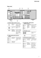
...a TV or a projector. You OUTPUT jacka) can enjoy high quality image. STR-K1500 Rear panel 1 23 4 DIGITAL OPTICAL VIDEO 1 IN VIDEO 2 IN ANTENNA AM DVD IN VIDEO 2 IN MONITOR OUT COMPONENT VIDEO ASSIGNABLE Y ASSIGNABLE HDMI MONITOR PB/CB /B-Y PR/CR /R-Y VIDEO IN ...INPUT/ satellite tuner. SURROUND BACK L L + - + - Yellow VIDEO IN/ OUT jacka) C COMPONENT VIDEO INPUT/ OUTPUT section Green Blue Red COMPONENT Connects to an MD deck or CD player, etc. D SPEAKER section Connects to a DVD IN jack player, etc. The COAXIAL jack provides a better COAXIAL IN quality...
...a TV or a projector. You OUTPUT jacka) can enjoy high quality image. STR-K1500 Rear panel 1 23 4 DIGITAL OPTICAL VIDEO 1 IN VIDEO 2 IN ANTENNA AM DVD IN VIDEO 2 IN MONITOR OUT COMPONENT VIDEO ASSIGNABLE Y ASSIGNABLE HDMI MONITOR PB/CB /B-Y PR/CR /R-Y VIDEO IN ...INPUT/ satellite tuner. SURROUND BACK L L + - + - Yellow VIDEO IN/ OUT jacka) C COMPONENT VIDEO INPUT/ OUTPUT section Green Blue Red COMPONENT Connects to an MD deck or CD player, etc. D SPEAKER section Connects to a DVD IN jack player, etc. The COAXIAL jack provides a better COAXIAL IN quality...
Service Manual
Page 9
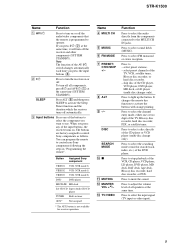
... DVD player, MD deck, or LD player (multi-disc changer only). To turn off all speakers at the same time. When you want to use. Press to select FM monaural or stereo ... of the input buttons, the receiver turns on. Press to light up the button. STR-K1500 Name Function A AV ?/1 Press to turn on or off the audio/video components that the remote is not available... sound fields (MUSIC). DISC SEARCH MODE Jx K MUTING L MASTER VOL +a)/- Press to control Sony components as follows. Press to activate the buttons with orange printing. Press to select the channel entry ...
... DVD player, MD deck, or LD player (multi-disc changer only). To turn off all speakers at the same time. When you want to use. Press to select FM monaural or stereo ... of the input buttons, the receiver turns on. Press to light up the button. STR-K1500 Name Function A AV ?/1 Press to turn on or off the audio/video components that the remote is not available... sound fields (MUSIC). DISC SEARCH MODE Jx K MUTING L MASTER VOL +a)/- Press to control Sony components as follows. Press to activate the buttons with orange printing. Press to select the channel entry ...

Service Manual
Page 12
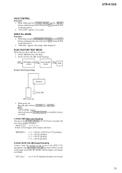
STR-K1500 SECTION 2 TEST MODE FACTORY PRESET MODE All preset contents are reset to the...MONO DIRECT dB kHz mft. Turn the INPUT SELECTOR dial once again. All segments turn on the main power. 2. While depressing the SPEAKERS (ON/OFF) and the 2CH buttons simultaneously, press the power ?/1 button to AM. Procedure: 1. Procedure: 1. "CLEARED" appears ...RANGE EQ STEREO MONO DIRECT C SL SR kHz mft. Turn the INPUT SELECTOR dial once again. While depressing the SPEAKERS (ON/OFF) and the MOVIE buttons simultaneously, press the power ?/1 button to turn on one after another in ...
STR-K1500 SECTION 2 TEST MODE FACTORY PRESET MODE All preset contents are reset to the...MONO DIRECT dB kHz mft. Turn the INPUT SELECTOR dial once again. All segments turn on the main power. 2. While depressing the SPEAKERS (ON/OFF) and the 2CH buttons simultaneously, press the power ?/1 button to AM. Procedure: 1. Procedure: 1. "CLEARED" appears ...RANGE EQ STEREO MONO DIRECT C SL SR kHz mft. Turn the INPUT SELECTOR dial once again. While depressing the SPEAKERS (ON/OFF) and the MOVIE buttons simultaneously, press the power ?/1 button to turn on one after another in ...
Service Manual
Page 13
...Start DSP Data Line Pass Check Auto Cal Mic Check Pass END Factory Test System Setup Receiver DCAC MIC SPK Front Left 1. Afterward, press the TUNING MODE to 255 (depends on loudness of the receiver and AUTO CAL microphone. "SWP.ALL" appears. (No change accordingly. When power ...off : Press the three buttons TUNING + + MOVIE + ?/1 . DCAC DSP Data Line Checking After press the TUNING MODE , DCAC Factory test mode will be test tone sound output from front left speaker of test tone) STR-K1500...
...Start DSP Data Line Pass Check Auto Cal Mic Check Pass END Factory Test System Setup Receiver DCAC MIC SPK Front Left 1. Afterward, press the TUNING MODE to 255 (depends on loudness of the receiver and AUTO CAL microphone. "SWP.ALL" appears. (No change accordingly. When power ...off : Press the three buttons TUNING + + MOVIE + ?/1 . DCAC DSP Data Line Checking After press the TUNING MODE , DCAC Factory test mode will be test tone sound output from front left speaker of test tone) STR-K1500...

Service Manual
Page 15
• Circuit Boards Location SPEAKER B board POWER board STANDBY board AC SELECT board (E51 only) SPEAKER C/SB board VIDEO board HDMI board (SP, SP6, AUS) ADCC board HEADPHONE board VIDEO 3 board DISPLAY board DIGITAL board MAIN board • Waveforms - DIGITAL Board - 1 IC1501 9 (MCLK1) 72 ns 1 V/DIV, 40 ns/DIV 2 IC1101 id (X1) 3.4 Vp-p 41.6 ns 1 V/DIV, 20 ns/DIV 3 IC1301 ws (XIN) 4.2 Vp-p 81 ns 1 V/DIV, 40 ns/DIV 4.4 Vp-p STR-K1500 Ver. 1.1 STR-K1500 15 15
• Circuit Boards Location SPEAKER B board POWER board STANDBY board AC SELECT board (E51 only) SPEAKER C/SB board VIDEO board HDMI board (SP, SP6, AUS) ADCC board HEADPHONE board VIDEO 3 board DISPLAY board DIGITAL board MAIN board • Waveforms - DIGITAL Board - 1 IC1501 9 (MCLK1) 72 ns 1 V/DIV, 40 ns/DIV 2 IC1101 id (X1) 3.4 Vp-p 41.6 ns 1 V/DIV, 20 ns/DIV 3 IC1301 ws (XIN) 4.2 Vp-p 81 ns 1 V/DIV, 40 ns/DIV 4.4 Vp-p STR-K1500 Ver. 1.1 STR-K1500 15 15

Service Manual
Page 17
...OUT1 3 Q110 LED DRIVE D105 Q534 BOOSTER FL_LAT SYSTEM CONTROL IC1101(2/2) X0 X1 A/D1 A/D2 ADCC STR-K1500 J2000 AUTO CAL MIC 82 83 39 40 38 X1101 24MHz FUNCTION KEY S108-111,115 FUNCTION KEY...Q710 RELAY DRIVE RY701 R-CH TM601 L R J791 PHONES FRONT R-CH Q610 RELAY DRIVE RY601 SR SURROUND SL SPEAKERS IMPEDANCE USE 6-16Ω Q550 RELAY DRIVE RY501 TM501 C CENTER FL101 -20V +B SB SURROUND -B BACK ... DETECT 63 SIRCS 54 AVCC 35 VCC3 84 VCC5 23 RSTX 77 STOP 48 IC102 REMOTE 1 CONTROL RECEIVER IC1111 1 RESET 2 +3.3V +2.5V +5V TUNER +10V RELAY +B AUDIO +7V AUDIO +5V ...
...OUT1 3 Q110 LED DRIVE D105 Q534 BOOSTER FL_LAT SYSTEM CONTROL IC1101(2/2) X0 X1 A/D1 A/D2 ADCC STR-K1500 J2000 AUTO CAL MIC 82 83 39 40 38 X1101 24MHz FUNCTION KEY S108-111,115 FUNCTION KEY...Q710 RELAY DRIVE RY701 R-CH TM601 L R J791 PHONES FRONT R-CH Q610 RELAY DRIVE RY601 SR SURROUND SL SPEAKERS IMPEDANCE USE 6-16Ω Q550 RELAY DRIVE RY501 TM501 C CENTER FL101 -20V +B SB SURROUND -B BACK ... DETECT 63 SIRCS 54 AVCC 35 VCC3 84 VCC5 23 RSTX 77 STOP 48 IC102 REMOTE 1 CONTROL RECEIVER IC1111 1 RESET 2 +3.3V +2.5V +5V TUNER +10V RELAY +B AUDIO +7V AUDIO +5V ...
Service Manual
Page 25
... BOARD CNS501 (Page 19) E F G DIGITAL BOARD CNS502 (Page 19) G H I STR-K1500 C3013 C3012 2 3 4 5 SA-CD/CD ADCC VIDEO 3 BOARD BOARD IN OUT CNP2000 CN201... 15 1 15 IC601 1 4 1 E E E 5 1 E 1 5 E E E E 4 1 3 1 1 4 1 5 1 6 B C E E E E E E E E E E E E E E E E E E E E E E B CE B CE E B CE B CE E B CE B CE E B CE B CE E B CE B CE E B CE B E CE 15 SPEAKER C/SB BOARD CNP503 (Page 32) M STANDBY BOARD CNP801 (Page 31) N O POWER TRANSFORMER T901 (Page 31) E DIGITAL BOARD CNP505 (Page 19) Q POWER TRANSFORMER T901 (Page 31...
... BOARD CNS501 (Page 19) E F G DIGITAL BOARD CNS502 (Page 19) G H I STR-K1500 C3013 C3012 2 3 4 5 SA-CD/CD ADCC VIDEO 3 BOARD BOARD IN OUT CNP2000 CN201... 15 1 15 IC601 1 4 1 E E E 5 1 E 1 5 E E E E 4 1 3 1 1 4 1 5 1 6 B C E E E E E E E E E E E E E E E E E E E E E E B CE B CE E B CE B CE E B CE B CE E B CE B CE E B CE B CE E B CE B E CE 15 SPEAKER C/SB BOARD CNP503 (Page 32) M STANDBY BOARD CNP801 (Page 31) N O POWER TRANSFORMER T901 (Page 31) E DIGITAL BOARD CNP505 (Page 19) Q POWER TRANSFORMER T901 (Page 31...

Service Manual
Page 29
... - 3-14. No. DISPLAY BOARD, POWER BOARD - • See page 15 for Circuit Boards Location. :Uses unleaded solder. Location D105 A-9 IC100 C-9 IC101 D-8 H IC102 C-6 Q110 A-8 ?/1 4 1 SPEAKERS (ON/OFF) STR-K1500 29 29 STR-K1500 1 A B CC DIGITAL BOARD CNS505 (Page 19) D E 2 3 4 5 6 7 8 9 10 11 12 13 14 MASTER VOLUME MUTING MULTI CH IN INPUT MODE DISPLAY INPUT SELECTOR R131...
... - 3-14. No. DISPLAY BOARD, POWER BOARD - • See page 15 for Circuit Boards Location. :Uses unleaded solder. Location D105 A-9 IC100 C-9 IC101 D-8 H IC102 C-6 Q110 A-8 ?/1 4 1 SPEAKERS (ON/OFF) STR-K1500 29 29 STR-K1500 1 A B CC DIGITAL BOARD CNS505 (Page 19) D E 2 3 4 5 6 7 8 9 10 11 12 13 14 MASTER VOLUME MUTING MULTI CH IN INPUT MODE DISPLAY INPUT SELECTOR R131...

Service Manual
Page 32
SURROUND BACK + - SPEAKER C/SB BOARD - • See page 15 for Circuit Boards Location. :Uses unleaded solder. 1 2 3 4 5 SPEAKER C/SB BOARD A TM501 CENTER +- B C D E STR-K1500 3 1 E R TM MAIN BOARD CNP806 (Page 25) MAIN MAIN BOARD BOARD WP02 CN808 (Page 25) (Page 25) U MAIN BOARD WP03 (Page 25) 32 32 PRINTED WIRING BOARD - STR-K1500 3-17.
SURROUND BACK + - SPEAKER C/SB BOARD - • See page 15 for Circuit Boards Location. :Uses unleaded solder. 1 2 3 4 5 SPEAKER C/SB BOARD A TM501 CENTER +- B C D E STR-K1500 3 1 E R TM MAIN BOARD CNP806 (Page 25) MAIN MAIN BOARD BOARD WP02 CN808 (Page 25) (Page 25) U MAIN BOARD WP03 (Page 25) 32 32 PRINTED WIRING BOARD - STR-K1500 3-17.

Service Manual
Page 45
... output I Fuse detect signal input I Volume signal input from rotary encoder I Volume signal input from rotary encoder O Front A speaker relay control signal output O Front B speaker control signal output O Center speaker relay control signal output O Rear speaker control signal output O Sub woofer control signal output O Analog switch IC clock signal output O Brigeable relay control output... signal output terminal O Reset signal output to DIR O CKSEL control signal output to DIR O Clock signal output to DIR O Chip enable signal output to DIR STR-K1500 45
... output I Fuse detect signal input I Volume signal input from rotary encoder I Volume signal input from rotary encoder O Front A speaker relay control signal output O Front B speaker control signal output O Center speaker relay control signal output O Rear speaker control signal output O Sub woofer control signal output O Analog switch IC clock signal output O Brigeable relay control output... signal output terminal O Reset signal output to DIR O CKSEL control signal output to DIR O Clock signal output to DIR O Chip enable signal output to DIR STR-K1500 45

Service Manual
Page 60
...CARBON 1K 5% 1/4W < SWITCH > S100 1-771-410-21 SWITCH, TACTILE (?/1) S115 1-771-410-21 SWITCH, TACTILE (SPEAKERS/ON/OFF SPEAKER C/SB BOARD < CAPACITOR > CC16 1-127-876-11 CERAMIC CC17 1-127-876-11 CERAMIC 0.01uF 10% 50V 0.01uF 10%...0 R765 0 R766 0 R767 0 R768 1-249-399-11 CARBON 33 5% 1-249-399-11 CARBON 33 5% 1-234-182-11 ENCAPSULATED COMPONENT 1-249-393-11 CARBON 10 5% 1-249-389-11 CARBON 4.7 5% R769 0 R771 R772 R773 R775 1-247-847-91 CARBON 1-240-... 1/4W 1/4W 1/4W 1/2W 1/4W 1/4W Ref. No. Part No. No. STR-K1500 Ver. 1.1 MAIN POWER SPEAKER C/SB STANDBY Ref.
...CARBON 1K 5% 1/4W < SWITCH > S100 1-771-410-21 SWITCH, TACTILE (?/1) S115 1-771-410-21 SWITCH, TACTILE (SPEAKERS/ON/OFF SPEAKER C/SB BOARD < CAPACITOR > CC16 1-127-876-11 CERAMIC CC17 1-127-876-11 CERAMIC 0.01uF 10% 50V 0.01uF 10%...0 R765 0 R766 0 R767 0 R768 1-249-399-11 CARBON 33 5% 1-249-399-11 CARBON 33 5% 1-234-182-11 ENCAPSULATED COMPONENT 1-249-393-11 CARBON 10 5% 1-249-389-11 CARBON 4.7 5% R769 0 R771 R772 R773 R775 1-247-847-91 CARBON 1-240-... 1/4W 1/4W 1/4W 1/2W 1/4W 1/4W Ref. No. Part No. No. STR-K1500 Ver. 1.1 MAIN POWER SPEAKER C/SB STANDBY Ref.


