
Service Manual
Page 1
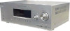
...Inputs (Digital) DVD (Coaxial) VIDEO 1, 2 (Optical) Sensitivity: - Continued on the sound field settings and the source, there may be no sound output. Impedance: - SERVICE MANUAL Ver. 1.1 2006.05 STR-K1500 E Model Australian Model • STR-K1500 is the tuner and the amplifier section in HT-DDW1500. Outputs (Analog) MD/TAPE (OUT), VIDEO 1 (AUDIO OUT) SUB WOOFER Voltage: 800 mV Impedance: 10 kohms Voltage: 2 V Impedance: 1 kohm Reproduction frequency range: Tone 28 - 20,000 Hz Gain levels ±6 dB, 1 dB step FM tuner section Tuning range 87.5 - 108.0 MHz Antenna FM wire...
...Inputs (Digital) DVD (Coaxial) VIDEO 1, 2 (Optical) Sensitivity: - Continued on the sound field settings and the source, there may be no sound output. Impedance: - SERVICE MANUAL Ver. 1.1 2006.05 STR-K1500 E Model Australian Model • STR-K1500 is the tuner and the amplifier section in HT-DDW1500. Outputs (Analog) MD/TAPE (OUT), VIDEO 1 (AUDIO OUT) SUB WOOFER Voltage: 800 mV Impedance: 10 kohms Voltage: 2 V Impedance: 1 kohm Reproduction frequency range: Tone 28 - 20,000 Hz Gain levels ±6 dB, 1 dB step FM tuner section Tuning range 87.5 - 108.0 MHz Antenna FM wire...

Service Manual
Page 2
... TUNING MODE, press ?/1. Parts No. CENTER + - SURROUND BACK L L + - + - STR-K1500 Ver. 1.1 AM tuner section Tuning range Models of area code SP, SP6, AUS With 9-kHz tuning scale: 531 - 1,602 kHz Models of area code E51 With 10-kHz tuning scale: 530 - 1,610 kHz4) With 9-kHz tuning scale: 531 - 1,602 kHz4) Models of the receiver you change the tuning scale. To reset the scale to change the AM tuning scale to 9 kHz or 10 kHz. Rear Panel - MODEL...
... TUNING MODE, press ?/1. Parts No. CENTER + - SURROUND BACK L L + - + - STR-K1500 Ver. 1.1 AM tuner section Tuning range Models of area code SP, SP6, AUS With 9-kHz tuning scale: 531 - 1,602 kHz Models of area code E51 With 10-kHz tuning scale: 530 - 1,610 kHz4) With 9-kHz tuning scale: 531 - 1,602 kHz4) Models of the receiver you change the tuning scale. To reset the scale to change the AM tuning scale to 9 kHz or 10 kHz. Rear Panel - MODEL...
Service Manual
Page 3
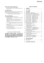
... TO SAFE OPERATION. Block Diagram - Block Diagram - MAIN Board (2/3 27 3-13. Schematic Diagram - ADCC Board, VIDEO 3 Board - 35 3-21. VIDEO Board, HEADPHONE Board 36 3-22. HDMI Board 39 4. DIGITAL Board (Side B) - ...... 19 3-5. STANDBY Board, AC SELECT Board 31 3-17. DIGITAL Board (1/5 20 3-6. Schematic Diagram - HDMI Board 38 3-24. Schematic Diagram - REPLACE THESE COMPONENTS WITH SONY PARTS WHOSE PART NUMBERS APPEAR AS SHOWN IN THIS MANUAL OR IN SUPPLEMENTS PUBLISHED BY SONY. DIGITAL Board (3/5 22 3-8. DIGITAL Board (5/5 24...
... TO SAFE OPERATION. Block Diagram - Block Diagram - MAIN Board (2/3 27 3-13. Schematic Diagram - ADCC Board, VIDEO 3 Board - 35 3-21. VIDEO Board, HEADPHONE Board 36 3-22. HDMI Board 39 4. DIGITAL Board (Side B) - ...... 19 3-5. STANDBY Board, AC SELECT Board 31 3-17. DIGITAL Board (1/5 20 3-6. Schematic Diagram - HDMI Board 38 3-24. Schematic Diagram - REPLACE THESE COMPONENTS WITH SONY PARTS WHOSE PART NUMBERS APPEAR AS SHOWN IN THIS MANUAL OR IN SUPPLEMENTS PUBLISHED BY SONY. DIGITAL Board (3/5 22 3-8. DIGITAL Board (5/5 24...

Service Manual
Page 4
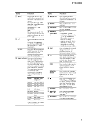
... lamp channel audio is extracted from children. F DISPLAY Press to the supplied ECM-AC2 optimizer microphone for the Auto Calibration function. Press to both digital and analog jacks . G INPUT MODE Press to select the input mode when the same components are connected to select sound fields (MOVIE, MUSIC). H MASTER VOLUME Turn to select A.F.D. K INPUT SELECTOR L MOVIE, MUSIC M A.F.D. N 2CH O TUNING +/- STR-K1500 Receiver Front panel 12 SECTION 1 GENERAL This section is decoded. Press to adjust the volume level of all speakers at the same time. ql...
... lamp channel audio is extracted from children. F DISPLAY Press to the supplied ECM-AC2 optimizer microphone for the Auto Calibration function. Press to both digital and analog jacks . G INPUT MODE Press to select the input mode when the same components are connected to select sound fields (MOVIE, MUSIC). H MASTER VOLUME Turn to select A.F.D. K INPUT SELECTOR L MOVIE, MUSIC M A.F.D. N 2CH O TUNING +/- STR-K1500 Receiver Front panel 12 SECTION 1 GENERAL This section is decoded. Press to adjust the volume level of all speakers at the same time. ql...

Service Manual
Page 5
... A SW B LFE C SP D ;DIGITAL (EX) Function Lights up when DTS signals are input. "; Note When playing a DTS format disc, be sure that you have made digital connections and that INPUT MODE is activated. PRO LOGIC IIx" lights up when DTS Neo:6 Cinema/Music decoder is not set to output the center and surround channel signals. STR-K1500 About the indicators on the display 1 23 4 5 67 8 9 SW LFE SP ;DIGITAL EX ;PRO LOGIC IIx DTS-ES NEO:6 SLEEP OPT COAX HDMI 96/24 D.RANGE LCR...
... A SW B LFE C SP D ;DIGITAL (EX) Function Lights up when DTS signals are input. "; Note When playing a DTS format disc, be sure that you have made digital connections and that INPUT MODE is activated. PRO LOGIC IIx" lights up when DTS Neo:6 Cinema/Music decoder is not set to output the center and surround channel signals. STR-K1500 About the indicators on the display 1 23 4 5 67 8 9 SW LFE SP ;DIGITAL EX ;PRO LOGIC IIx DTS-ES NEO:6 SLEEP OPT COAX HDMI 96/24 D.RANGE LCR...

Service Manual
Page 6
... the COAXIAL jack, or when INPUT MODE is set to tune in the VIDEO menu . Lights up when using the receiver to "OPT IN" . Front Left Front Right Center (monaural) Surround Left Surround Right Surround (monaural or the surround components obtained by Pro Logic processing) Surround back (the surround back components obtained by 6.1 channel decoding) Example: Recording format (Front/ Surround): 3/2.1 Sound Field: A.F.D. AUTO SW LCR SL SR * Except for models of area code MX, E51. 6 in radio stations you select "HDMI...
... the COAXIAL jack, or when INPUT MODE is set to tune in the VIDEO menu . Lights up when using the receiver to "OPT IN" . Front Left Front Right Center (monaural) Surround Left Surround Right Surround (monaural or the surround components obtained by Pro Logic processing) Surround back (the surround back components obtained by 6.1 channel decoding) Example: Recording format (Front/ Surround): 3/2.1 Sound Field: A.F.D. AUTO SW LCR SL SR * Except for models of area code MX, E51. 6 in radio stations you select "HDMI...
Service Manual
Page 7
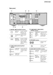
... analog audio jack for 5.1 channel sound. 7 White (L) Red (R) MULTI CHANNEL INPUT jack Black Connects to a DVD VIDEO player, TV, or a INPUT/ satellite tuner. D SPEAKER section Connects to the sub woofers. STR-K1500 Rear panel 1 23 4 DIGITAL OPTICAL VIDEO 1 IN VIDEO 2 IN ANTENNA AM DVD IN VIDEO 2 IN MONITOR OUT COMPONENT VIDEO ASSIGNABLE Y ASSIGNABLE HDMI MONITOR PB/CB /B-Y PR/CR /R-Y VIDEO IN VIDEO IN VIDEO OUT VIDEO IN VIDEO OUT DVD VIDEO 2 MONITOR IN IN OUT DVD IN COAXIAL D-LIGHT SYNC OUT L L R IN SA-CD/CD R OUT IN MD/TAPE AUDIO OUT L L L CENTER...
... analog audio jack for 5.1 channel sound. 7 White (L) Red (R) MULTI CHANNEL INPUT jack Black Connects to a DVD VIDEO player, TV, or a INPUT/ satellite tuner. D SPEAKER section Connects to the sub woofers. STR-K1500 Rear panel 1 23 4 DIGITAL OPTICAL VIDEO 1 IN VIDEO 2 IN ANTENNA AM DVD IN VIDEO 2 IN MONITOR OUT COMPONENT VIDEO ASSIGNABLE Y ASSIGNABLE HDMI MONITOR PB/CB /B-Y PR/CR /R-Y VIDEO IN VIDEO IN VIDEO OUT VIDEO IN VIDEO OUT DVD VIDEO 2 MONITOR IN IN OUT DVD IN COAXIAL D-LIGHT SYNC OUT L L R IN SA-CD/CD R OUT IN MD/TAPE AUDIO OUT L L L CENTER...

Service Manual
Page 8
.../ AMP TV CH VIDEO MENU AUTO WIDE CAL qj 4 5 6 7 8 9 0 qa qs qd qf qg qh 8 a)You can also program the remote to the AM loop antenna supplied with this receiver . MOVIE MUSIC 1 2 3 DUAL FM MONO MODE 4 5 6 AUDIO ANGLE JUMP/ PRESET/ TUNING TIME CH/D.SKIP 7 8 9 MEMORY SUBTITLE ENTER .> 0/10 >10/11 12 D.TUNING DISC ALT mM - For details, see "Programming the remote". STR-K1500 F D-LIGHT SYNC OUT section D-LIGHT Connects to a TV monitor. AM ANTENNA Connects to control non-Sony audio/video components...
.../ AMP TV CH VIDEO MENU AUTO WIDE CAL qj 4 5 6 7 8 9 0 qa qs qd qf qg qh 8 a)You can also program the remote to the AM loop antenna supplied with this receiver . MOVIE MUSIC 1 2 3 DUAL FM MONO MODE 4 5 6 AUDIO ANGLE JUMP/ PRESET/ TUNING TIME CH/D.SKIP 7 8 9 MEMORY SUBTITLE ENTER .> 0/10 >10/11 12 D.TUNING DISC ALT mM - For details, see "Programming the remote". STR-K1500 F D-LIGHT SYNC OUT section D-LIGHT Connects to a TV monitor. AM ANTENNA Connects to control non-Sony audio/video components...
Service Manual
Page 9
B ?/1 Press to turn the receiver on or off automatically. The buttons are factory assigned to the MULTI CH IN jacks. Name D MULTI CH E MUSIC F FM MODE G PRESET/ CH/D.SKIP +/- M TV/VIDEO Function Press to select the audio directly from the components connected to control Sony components as follows. Press to stop playback of the AV ?/1 switch changes automatically each time you want to use. To turn off all speakers at the same time. SLEEP Press ALT (H) and then press...
B ?/1 Press to turn the receiver on or off automatically. The buttons are factory assigned to the MULTI CH IN jacks. Name D MULTI CH E MUSIC F FM MODE G PRESET/ CH/D.SKIP +/- M TV/VIDEO Function Press to select the audio directly from the components connected to control Sony components as follows. Press to stop playback of the AV ?/1 switch changes automatically each time you want to use. To turn off all speakers at the same time. SLEEP Press ALT (H) and then press...

Service Manual
Page 10
... player, VCD player, LD player, DVD player, MD deck, Blu-ray disc recorder, hard disc recorder, or PSX. - clear a mistake when you press TOP MENU/ GUIDE or AV MENU, press the control button to select the settings. Press to select preset TV channels. search tracks in recording standby.) Press to the previous menu. - exit the menu while the menu or on the TV screen. Press to - Name W AV MENU X Ha) YX Z m/M D. return to - STR-K1500 Name N AMP MENU O AUTO...
... player, VCD player, LD player, DVD player, MD deck, Blu-ray disc recorder, hard disc recorder, or PSX. - clear a mistake when you press TOP MENU/ GUIDE or AV MENU, press the control button to select the settings. Press to select preset TV channels. search tracks in recording standby.) Press to the previous menu. - exit the menu while the menu or on the TV screen. Press to - Name W AV MENU X Ha) YX Z m/M D. return to - STR-K1500 Name N AMP MENU O AUTO...

Service Manual
Page 11
... player, DVD player, MD deck, DAT deck, or tape deck. select channel numbers of the TV, VCR, satellite tuner, Blu-ray disc recorder, hard disc recorder, or PSX. >10/11 Press ALT (H) and then press >10/11 to serve as references when operating the receiver. a) The MASTER VOL +, TV VOL +, TV CH +, and H buttons have tactile dots. MEMORY Press to - DUAL MONO Press to select sound fields (MOVIE). STR-K1500 Name Function...
... player, DVD player, MD deck, DAT deck, or tape deck. select channel numbers of the TV, VCR, satellite tuner, Blu-ray disc recorder, hard disc recorder, or PSX. >10/11 Press ALT (H) and then press >10/11 to serve as references when operating the receiver. a) The MASTER VOL +, TV VOL +, TV CH +, and H buttons have tactile dots. MEMORY Press to - DUAL MONO Press to select sound fields (MOVIE). STR-K1500 Name Function...

Service Manual
Page 12
... COAX MULTI CH IN 96/24 D.RANGE EQ STEREO MONO DIRECT C SL SR kHz mft. The message "SF. The buttons which are already counted once are displayed. (7 second) KEY CHECK MODE Button check Procedure: 1. While depressing the SPEAKERS (ON/OFF) and the MUSIC buttons simultaneously, press the power ?/1 button to the default setting. SBL SB SBR MHz 3. Every pressing of repair. STR-K1500 SECTION 2 TEST MODE FACTORY PRESET MODE All preset contents are reset to turn...
... COAX MULTI CH IN 96/24 D.RANGE EQ STEREO MONO DIRECT C SL SR kHz mft. The message "SF. The buttons which are already counted once are displayed. (7 second) KEY CHECK MODE Button check Procedure: 1. While depressing the SPEAKERS (ON/OFF) and the MUSIC buttons simultaneously, press the power ?/1 button to the default setting. SBL SB SBR MHz 3. Every pressing of repair. STR-K1500 SECTION 2 TEST MODE FACTORY PRESET MODE All preset contents are reset to turn...
Service Manual
Page 13
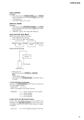
... display will change while displayed.) DCAC FACTORY TEST MODE DCAC Factory Test mode have two stages: 1. DCAC AUTO CAL MIC board Checking Start DSP Data Line Pass Check Auto Cal Mic Check Pass END Factory Test System Setup Receiver DCAC MIC SPK Front Left 1. DCAC DSP Data Line Checking After press the TUNING MODE , DCAC Factory test mode will start DCAC factory test mode. 1. Turn MASTER VOLUME jog, there will be test tone sound output from front left speaker of test tone) STR-K1500 13 When power off : Press the three buttons TUNING...
... display will change while displayed.) DCAC FACTORY TEST MODE DCAC Factory Test mode have two stages: 1. DCAC AUTO CAL MIC board Checking Start DSP Data Line Pass Check Auto Cal Mic Check Pass END Factory Test System Setup Receiver DCAC MIC SPK Front Left 1. DCAC DSP Data Line Checking After press the TUNING MODE , DCAC Factory test mode will start DCAC factory test mode. 1. Turn MASTER VOLUME jog, there will be test tone sound output from front left speaker of test tone) STR-K1500 13 When power off : Press the three buttons TUNING...

Service Manual
Page 14
... PRINTED WIRING BOARDS AND SCHEMATIC DIAGRAMS. (In addition to this, the necessary note is printed in each block.) For Schematic Diagrams. Note: • All capacitors are in Ω and 1/4 W or less unless otherwise specified. • % : indicates tolerance. • f : internal component. • 2 : nonflammable resistor. • 5 : fusible resistor. • C : panel designation. F : FM J : ANALOG c : DIGITAL I : VIDEO • Abbreviation AUS : Australian model. Parts on the parts face...
... PRINTED WIRING BOARDS AND SCHEMATIC DIAGRAMS. (In addition to this, the necessary note is printed in each block.) For Schematic Diagrams. Note: • All capacitors are in Ω and 1/4 W or less unless otherwise specified. • % : indicates tolerance. • f : internal component. • 2 : nonflammable resistor. • 5 : fusible resistor. • C : panel designation. F : FM J : ANALOG c : DIGITAL I : VIDEO • Abbreviation AUS : Australian model. Parts on the parts face...

Service Manual
Page 16
... MD/TAPE L • R-CH is omitted due to same as L-CH. • Signal Path : FM : ANALOG : DIGITAL : VIDEO SL DISPLAY A /POWER SECTION (Page 17) C R-CH SBL IC3001 AMP 2 1 +B IC402 WOOFER AMP 5 7 Q560 RELAY DRIVE CN3001 L+R D-LIGHT SYNC-OUT J309 AUDIO OUT SUB WOOFER IC1131 EEPROM SDA SCL 5 6 29 30 70 Q560 RELAY DRIVE RY560 COMPONENT VIDEO J301 (1/2) VIDEO 2 IN Y PB/CB/B-Y PR/CR/R-Y Y DVD IN PB/CB/B-Y PR/CR/R-Y STR-K1500...
... MD/TAPE L • R-CH is omitted due to same as L-CH. • Signal Path : FM : ANALOG : DIGITAL : VIDEO SL DISPLAY A /POWER SECTION (Page 17) C R-CH SBL IC3001 AMP 2 1 +B IC402 WOOFER AMP 5 7 Q560 RELAY DRIVE CN3001 L+R D-LIGHT SYNC-OUT J309 AUDIO OUT SUB WOOFER IC1131 EEPROM SDA SCL 5 6 29 30 70 Q560 RELAY DRIVE RY560 COMPONENT VIDEO J301 (1/2) VIDEO 2 IN Y PB/CB/B-Y PR/CR/R-Y Y DVD IN PB/CB/B-Y PR/CR/R-Y STR-K1500...

Service Manual
Page 17
... SURROUND SL SPEAKERS IMPEDANCE USE 6-16Ω Q550 RELAY DRIVE RY501 TM501 C CENTER FL101 -20V +B SB SURROUND -B BACK IC691 2 1 POWER AMP -B IC691 5 7 D1110 D1108 D1107 D1111 55 62 66 69 68 67 56 58 S100 ?/1 FUSE DETECT 63 SIRCS 54 AVCC 35 VCC3 84 VCC5 23 RSTX 77 STOP 48 IC102 REMOTE 1 CONTROL RECEIVER IC1111 1 RESET 2 +3.3V +2.5V +5V TUNER +10V RELAY +B AUDIO +7V AUDIO +5V AUDIO...
... SURROUND SL SPEAKERS IMPEDANCE USE 6-16Ω Q550 RELAY DRIVE RY501 TM501 C CENTER FL101 -20V +B SB SURROUND -B BACK IC691 2 1 POWER AMP -B IC691 5 7 D1110 D1108 D1107 D1111 55 62 66 69 68 67 56 58 S100 ?/1 FUSE DETECT 63 SIRCS 54 AVCC 35 VCC3 84 VCC5 23 RSTX 77 STOP 48 IC102 REMOTE 1 CONTROL RECEIVER IC1111 1 RESET 2 +3.3V +2.5V +5V TUNER +10V RELAY +B AUDIO +7V AUDIO +5V AUDIO...
Service Manual
Page 44
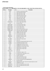
Power supply (+3.3V) O FL driver reset signal output O Not used 44 Analog power supply (+3.3V) I HACN signal input from DSP O Reset signal output to DSP O PM signal output to DSP O GP12 signal output to DSP O FL driver latch signal output O IC reset signal output to DAC - O Not used - STR-K1500 • IC Pin Function Description DIGITAL BOARD IC1101 MB90488BPF-G-175E1:MX, MB90488BPF-G-193E1: EXCEPT MX (SYSTEM CONTROL) Pin No. 1 2 3 4 5 6 7 8 9 10 11 12 13 14 15 16 17 18 19 20 21 22 23 24...
Power supply (+3.3V) O FL driver reset signal output O Not used 44 Analog power supply (+3.3V) I HACN signal input from DSP O Reset signal output to DSP O PM signal output to DSP O GP12 signal output to DSP O FL driver latch signal output O IC reset signal output to DAC - O Not used - STR-K1500 • IC Pin Function Description DIGITAL BOARD IC1101 MB90488BPF-G-175E1:MX, MB90488BPF-G-193E1: EXCEPT MX (SYSTEM CONTROL) Pin No. 1 2 3 4 5 6 7 8 9 10 11 12 13 14 15 16 17 18 19 20 21 22 23 24...

Service Manual
Page 45
...output I Protector status detect signal input O Headphone relay control signal output I Fuse detect signal input I Volume signal input from rotary encoder I Volume signal input from rotary encoder O Front A speaker relay control signal output O Front B speaker control signal output O Center speaker relay control signal output O Rear speaker control signal output O Sub woofer control signal output O Analog switch IC clock signal output O Brigeable relay control output I Frequency data signal input from the tuner O Latch signal output to the tuner I Tuning a frequency signal input...
...output I Protector status detect signal input O Headphone relay control signal output I Fuse detect signal input I Volume signal input from rotary encoder I Volume signal input from rotary encoder O Front A speaker relay control signal output O Front B speaker control signal output O Center speaker relay control signal output O Rear speaker control signal output O Sub woofer control signal output O Analog switch IC clock signal output O Brigeable relay control output I Frequency data signal input from the tuner O Latch signal output to the tuner I Tuning a frequency signal input...

Service Manual
Page 47
... mechanical parts with no reference number in the exploded views are not supplied. • Items marked "*" are not stocked since they are critical for routine service. FRONT PANEL SECTION STR-K1500 Ver. 1.1 The components identified by mark 0 or dotted line with mark 0 are seldom required for safety. Description Remark 2-661-142-11 VOLUME KNOB 2-661-141-11 MENU KNOB...
... mechanical parts with no reference number in the exploded views are not supplied. • Items marked "*" are not stocked since they are critical for routine service. FRONT PANEL SECTION STR-K1500 Ver. 1.1 The components identified by mark 0 or dotted line with mark 0 are seldom required for safety. Description Remark 2-661-142-11 VOLUME KNOB 2-661-141-11 MENU KNOB...

Service Manual
Page 49
... part number specified. • Abbreviation AUS : Australian model. SECTION 5 ELECTRICAL PARTS LIST STR-K1500 Ver. 1.1 AC SELECT ADCC DIGITAL NOTE: • Due to standardization, replacements in the parts list may have some difference from the original one. • RESISTORS All resistors are in the diagrams or the components used on the set. • -XX and -X mean standardized parts, so they are seldom required for routine service...
... part number specified. • Abbreviation AUS : Australian model. SECTION 5 ELECTRICAL PARTS LIST STR-K1500 Ver. 1.1 AC SELECT ADCC DIGITAL NOTE: • Due to standardization, replacements in the parts list may have some difference from the original one. • RESISTORS All resistors are in the diagrams or the components used on the set. • -XX and -X mean standardized parts, so they are seldom required for routine service...


