GUI Menu List
Page 1
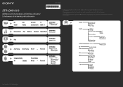
... Mode RF Change S-AIR Stby Lvl Dist Size*1 Test Tone Phase Noise Phase Audio Sound Field Effect Level*1 Sony Corporation © 2010 Printed in Malaysia Ctrl for HDMI Pass Through Audio Out SW Level SW L.P.F. 4-174-070-12(1) STR-DN1010 GUI Menu List/Liste des menus de l'interface utilisateur/ Lista de menús de...
... Mode RF Change S-AIR Stby Lvl Dist Size*1 Test Tone Phase Noise Phase Audio Sound Field Effect Level*1 Sony Corporation © 2010 Printed in Malaysia Ctrl for HDMI Pass Through Audio Out SW Level SW L.P.F. 4-174-070-12(1) STR-DN1010 GUI Menu List/Liste des menus de l'interface utilisateur/ Lista de menús de...

Operating Instructions
Page 2
... voltage" within the product's enclosure that may be of sufficient magnitude to constitute a risk of electric shock to rain or moisture. Excessive sound pressure from the AC outlet immediately. This symbol is used to disconnect the unit from the apparatus. 11)Only use this apparatus to persons...cause hearing loss. A grounding type plug has two blades and a third grounding prong. If the provided plug does not fit into your Sony dealer regarding this apparatus to an easily accessible AC outlet. Should you call upon your outlet, consult an electrician for your safety. Refer...
... voltage" within the product's enclosure that may be of sufficient magnitude to constitute a risk of electric shock to rain or moisture. Excessive sound pressure from the AC outlet immediately. This symbol is used to disconnect the unit from the apparatus. 11)Only use this apparatus to persons...cause hearing loss. A grounding type plug has two blades and a third grounding prong. If the provided plug does not fit into your Sony dealer regarding this apparatus to an easily accessible AC outlet. Should you call upon your outlet, consult an electrician for your safety. Refer...
Operating Instructions
Page 6
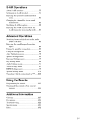
... to listen to the SIRIUS Satellite Radio 58 Selecting a channel of the SIRIUS Satellite Radio 59 Presetting SIRIUS Satellite Radio channels 61 Restricting access to specific channels (Parental Lock 62 Enjoying Surround Sound Selecting the sound field 65 Enjoying the surround effect at low volume levels ...TV sound from the speakers connected to the receiver (System Audio Control 72 Turning off the receiver with the TV (System Power Off 73 Enjoying movies with the optimum sound field (Theater/Theatre Mode Sync)........ 73 Enjoying the TV sound via an HDMI cable (Audio Return Channel 74
... to listen to the SIRIUS Satellite Radio 58 Selecting a channel of the SIRIUS Satellite Radio 59 Presetting SIRIUS Satellite Radio channels 61 Restricting access to specific channels (Parental Lock 62 Enjoying Surround Sound Selecting the sound field 65 Enjoying the surround effect at low volume levels ...TV sound from the speakers connected to the receiver (System Audio Control 72 Turning off the receiver with the TV (System Power Off 73 Enjoying movies with the optimum sound field (Theater/Theatre Mode Sync)........ 73 Enjoying the TV sound via an HDMI cable (Audio Return Channel 74
Operating Instructions
Page 7
S-AIR Operations About S-AIR products 75 Setting up an S-AIR product 76 Enjoying the system's sound in another room 80 Changing the channel for better sound transmission 81 Stabilizing S-AIR reception 82 Enjoying the S-AIR receiver while the S-AIR main unit is in standby mode...... 83 Advanced Operations Switching between digital and analog audio (INPUT...
S-AIR Operations About S-AIR products 75 Setting up an S-AIR product 76 Enjoying the system's sound in another room 80 Changing the channel for better sound transmission 81 Stabilizing S-AIR reception 82 Enjoying the S-AIR receiver while the S-AIR main unit is in standby mode...... 83 Advanced Operations Switching between digital and analog audio (INPUT...
Operating Instructions
Page 9
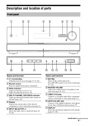
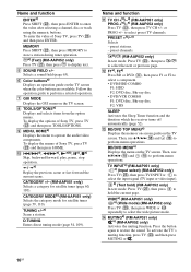
... or off (page 37, 55, 69). J AUTO CAL MIC jack Connects to restore the sound (page 47, 122). continued 9GB K DISPLAY Selects the information displayed on . D MULTI CHANNEL DECODING indicator Lights up when the receiver is off the sound temporarily. Name and function G MUTING Turns off . F INPUT SELECTOR +/- Press MUTING again to the supplied optimizer...
... or off (page 37, 55, 69). J AUTO CAL MIC jack Connects to restore the sound (page 47, 122). continued 9GB K DISPLAY Selects the information displayed on . D MULTI CHANNEL DECODING indicator Lights up when the receiver is off the sound temporarily. Name and function G MUTING Turns off . F INPUT SELECTOR +/- Press MUTING again to the supplied optimizer...

Operating Instructions
Page 10
N 2CH/A.DIRECT, A.F.D., MOVIE, MUSIC Selects a sound field (page 65, 66). P PHONES jack Connects to both digital and analog jacks (page 84). Name and function L DIMMER Adjusts the brightness of the display (page 111). M INPUT MODE Selects the input mode when the same components are connected to headphones (page 122). 10GB O SPEAKERS Selects the front speaker system (page 37).
N 2CH/A.DIRECT, A.F.D., MOVIE, MUSIC Selects a sound field (page 65, 66). P PHONES jack Connects to both digital and analog jacks (page 84). Name and function L DIMMER Adjusts the brightness of the display (page 111). M INPUT MODE Selects the input mode when the same components are connected to headphones (page 122). 10GB O SPEAKERS Selects the front speaker system (page 37).
Operating Instructions
Page 11
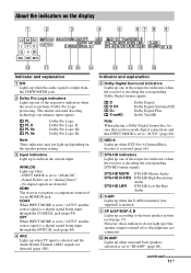
...SB R PLll x z ANALOGHDMI COAX OPT ARC D + EX TrueHD NEO 6 LF E EQ RDS CAT MEM DTS - Sound Field is a digital signal being input through the COAXIAL jack (page 84). COAX When INPUT MODE is set to "AUTO"... decoder is set to "AUTO" (page 84). No digital signals are connected. HDMI The receiver recognizes a component connected via an HDMI IN jack. Indicator and explanation E Dolby Digital Surround indicators... 37). C Input indicators Light up when the audio signal is selected and the Audio Return Channel (ARC) signals are detected (page 100). OPT When INPUT MODE is set to "AUTO"...
...SB R PLll x z ANALOGHDMI COAX OPT ARC D + EX TrueHD NEO 6 LF E EQ RDS CAT MEM DTS - Sound Field is a digital signal being input through the COAXIAL jack (page 84). COAX When INPUT MODE is set to "AUTO"... decoder is set to "AUTO" (page 84). No digital signals are connected. HDMI The receiver recognizes a component connected via an HDMI IN jack. Indicator and explanation E Dolby Digital Surround indicators... 37). C Input indicators Light up when the audio signal is selected and the Audio Return Channel (ARC) signals are detected (page 100). OPT When INPUT MODE is set to "AUTO"...
Operating Instructions
Page 12
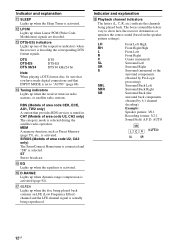
... Pro Logic processing) Surround Back Left Surround Back Right Surround Back (the surround back components obtained by 6.1 channel decoding) Example: Speaker pattern: 3/0.1 Recording format: 3/2.1 Sound Field: A.F.D. Indicator and explanation K SLEEP Lights up when the disc being played back contains an LFE (Low... Effect) channel and the LFE channel signal is actually being played back. M DTS(-ES) indicators Lights up one of area code CEK, ECE, AU1, TW2 only) A station that INPUT MODE is set to show how the receiver downmixes or upmixes the source sound (based on...
... Pro Logic processing) Surround Back Left Surround Back Right Surround Back (the surround back components obtained by 6.1 channel decoding) Example: Speaker pattern: 3/0.1 Recording format: 3/2.1 Sound Field: A.F.D. Indicator and explanation K SLEEP Lights up when the disc being played back contains an LFE (Low... Effect) channel and the LFE channel signal is actually being played back. M DTS(-ES) indicators Lights up one of area code CEK, ECE, AU1, TW2 only) A station that INPUT MODE is set to show how the receiver downmixes or upmixes the source sound (based on...
Operating Instructions
Page 13
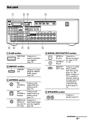
... section Connects to the supplied FM wire antenna (aerial) (page 35). HDMI IN/ OUT* jacks Connects to this receiver (page 23, 27). The image is output to a TV or a projector while the sound can be output from a TV or/and speakers connected to a DVD player, satellite tuner, Blu-ray disc player, etc... panel 1 23 4 86 76 5 A S-AIR section EZW-T100 slot Connects to the supplied AM loop antenna (aerial) (page 35). B DMPORT section DMPORT jack Connects to a Sony DIGITAL MEDIA PORT adapter (page 24).
... section Connects to the supplied FM wire antenna (aerial) (page 35). HDMI IN/ OUT* jacks Connects to this receiver (page 23, 27). The image is output to a TV or a projector while the sound can be output from a TV or/and speakers connected to a DVD player, satellite tuner, Blu-ray disc player, etc... panel 1 23 4 86 76 5 A S-AIR section EZW-T100 slot Connects to the supplied AM loop antenna (aerial) (page 35). B DMPORT section DMPORT jack Connects to a Sony DIGITAL MEDIA PORT adapter (page 24).
Operating Instructions
Page 16
... disc F2: VHS SLEEP Activates the Sleep Timer function and the duration which the receiver turns off automatically (page 52). L F1a), F2a) Press BD or DVD (D),...then press ENTER to select preset TV channels. To display the options of Sony TV, press TV (W) and then press ENTER. to enter the value after selecting a channel, disc or track using the numeric buttons... then press WIDE or repeatedly to hold the current page. E SOUND FIELD +/- or PROG +/- preset channels. Then, use V/v/B/b (R) and (R) to restore the sound. CATEGORY MODEb) (RM-AAP051 only) Selects the category mode for...
... disc F2: VHS SLEEP Activates the Sleep Timer function and the duration which the receiver turns off automatically (page 52). L F1a), F2a) Press BD or DVD (D),...then press ENTER to select preset TV channels. To display the options of Sony TV, press TV (W) and then press ENTER. to enter the value after selecting a channel, disc or track using the numeric buttons... then press WIDE or repeatedly to hold the current page. E SOUND FIELD +/- or PROG +/- preset channels. Then, use V/v/B/b (R) and (R) to restore the sound. CATEGORY MODEb) (RM-AAP051 only) Selects the category mode for...
Operating Instructions
Page 19
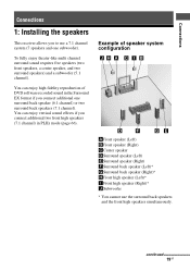
... one subwoofer). continued 19GB To fully enjoy theater-like multi channel surround sound requires five speakers (two front speakers, a center speaker, and two surround speakers) and a subwoofer (5.1 channel). Example of DVD software recorded sound in PLIIz mode (page 66). Connections Connections 1: Installing the speakers This receiver allows you to use the surround back speakers and the...
... one subwoofer). continued 19GB To fully enjoy theater-like multi channel surround sound requires five speakers (two front speakers, a center speaker, and two surround speakers) and a subwoofer (5.1 channel). Example of DVD software recorded sound in PLIIz mode (page 66). Connections Connections 1: Installing the speakers This receiver allows you to use the surround back speakers and the...
Operating Instructions
Page 22
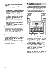
... Not doing so may not be sure to "BI-AMP" in the Speaker Settings menu (page 91). 22GB Set "SB Assign" to a subwoofer, then sound may cause a malfunction of the input signal to "Speaker B" in the Speaker Settings menu (page 91). Front speaker (Right) Front speaker (Left) Hi ... speakers or front high speakers, you connect a subwoofer with an auto standby function, turn off the function when watching movies. a)Notes on the receiver (page 37). - You can select the front speaker system you have an additional front speaker system, connect the additional front speaker system to "...
... Not doing so may not be sure to "BI-AMP" in the Speaker Settings menu (page 91). 22GB Set "SB Assign" to a subwoofer, then sound may cause a malfunction of the input signal to "Speaker B" in the Speaker Settings menu (page 91). Front speaker (Right) Front speaker (Left) Hi ... speakers or front high speakers, you connect a subwoofer with an auto standby function, turn off the function when watching movies. a)Notes on the receiver (page 37). - You can select the front speaker system you have an additional front speaker system, connect the additional front speaker system to "...
Operating Instructions
Page 24
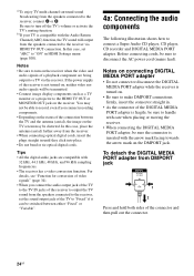
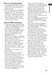
... enjoy TV multi channel surround sound broadcasting from the receiver. • When connecting optical digital cords, insert the plugs straight in until they click into place. • Do not bend or tie optical digital cords. b)If your TV is compatible with the Audio Return Channel (ARC) function, the TV sound will be ... the speakers connected to a TV via HDMI TV OUT connection. You may be sure to the receiver via the receiver. In this case, set the sound output jack of the receiver is turned on the status of the connector and then pull out the connector. 24GB To detach ...
... enjoy TV multi channel surround sound broadcasting from the receiver. • When connecting optical digital cords, insert the plugs straight in until they click into place. • Do not bend or tie optical digital cords. b)If your TV is compatible with the Audio Return Channel (ARC) function, the TV sound will be ... the speakers connected to a TV via HDMI TV OUT connection. You may be sure to the receiver via the receiver. In this case, set the sound output jack of the receiver is turned on the status of the connector and then pull out the connector. 24GB To detach ...
Operating Instructions
Page 26
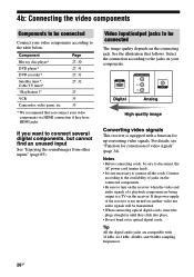
... Components to be connected Connect your video components according to connect several digital components, but cannot find an unused input See "Enjoying the sound/images from other inputs" (page 85). See the illustration that you want to the table below. For details, see "Function for ... of video signals" (page 34). HDMI Digital COMPONENT VIDEO Y PB/CB PR/CR VIDEO Analog High quality image Converting video signals This receiver is not turned on the connecting jack. Select the connection according to connect all the cords. Component Page Blu-ray disc player* DVD player...
... Components to be connected Connect your video components according to connect several digital components, but cannot find an unused input See "Enjoying the sound/images from other inputs" (page 85). See the illustration that you want to the table below. For details, see "Function for ... of video signals" (page 34). HDMI Digital COMPONENT VIDEO Y PB/CB PR/CR VIDEO Analog High quality image Converting video signals This receiver is not turned on the connecting jack. Select the connection according to connect all the cords. Component Page Blu-ray disc player* DVD player...
Operating Instructions
Page 28
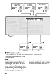
... the button to control your component to the HDMI IN 3 (for AUDIO) jack and select HDMI 3 as input. • Be sure to the receiver, see page 23. Satellite tuner, Cable TV tuner Audio/video signals A DVD player, DVD recorder Audio/video signals A Blu-ray disc player Audio/video... Sony recommends that you can be displayed on the remote so that it can use an HDMI-authorized cable or Sony HDMI cable. * For details on the audio connection of TV to change the initial setting of the HDMI 1-4 input button on the receiver's display. Notes • HDMI 3 input has a better sound ...
... the button to control your component to the HDMI IN 3 (for AUDIO) jack and select HDMI 3 as input. • Be sure to the receiver, see page 23. Satellite tuner, Cable TV tuner Audio/video signals A DVD player, DVD recorder Audio/video signals A Blu-ray disc player Audio/video... Sony recommends that you can be displayed on the remote so that it can use an HDMI-authorized cable or Sony HDMI cable. * For details on the audio connection of TV to change the initial setting of the HDMI 1-4 input button on the receiver's display. Notes • HDMI 3 input has a better sound ...
Operating Instructions
Page 29
... For example, components that are being output to a TV via the HDMI cable. • Sound may be made before you connect an HDMI-DVI conversion cable to the receiver using an HDMI-DVI conversion cable. When you can enjoy multi channel Linear PCM. If you cannot play back a 3D-compatible content. • Depending on...
... For example, components that are being output to a TV via the HDMI cable. • Sound may be made before you connect an HDMI-DVI conversion cable to the receiver using an HDMI-DVI conversion cable. When you can enjoy multi channel Linear PCM. If you cannot play back a 3D-compatible content. • Depending on...
Operating Instructions
Page 38
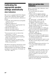
b)The measurement result is not utilized when signals with a sampling frequency of more than 96 kHz are being received. c)The measurement result is not utilized when signals with a sampling frequency of the sound cannot be set to "SPK OFF" (page 37). • Disconnect the headphones. • Remove any ... the AUTO CAL MIC jack. For details, see "Test Tone" (page 93). The DCAC is designed to obtain proper sound balance in the path between each speaker and the receiver.a) • Adjust the speaker level. • Measure the distance of noise and get a more than 48 kHz are...
b)The measurement result is not utilized when signals with a sampling frequency of more than 96 kHz are being received. c)The measurement result is not utilized when signals with a sampling frequency of the sound cannot be set to "SPK OFF" (page 37). • Disconnect the headphones. • Remove any ... the AUTO CAL MIC jack. For details, see "Test Tone" (page 93). The DCAC is designed to obtain proper sound balance in the path between each speaker and the receiver.a) • Adjust the speaker level. • Measure the distance of noise and get a more than 48 kHz are...

Operating Instructions
Page 41
Press ?/1. - When the measurement ends, a beep sounds. Press V/v repeatedly to use MUTING on the TV screen. However...after Auto Calibration measurement" (page 43). 2 View the measurement result. This is displayed on the receiver. - Preparing the Receiver To cancel Auto Calibration The Auto Calibration function will be connected the other way around. Press MUTING ...(RM-AAP051 only) or (RM-AAP052 only) on the receiver. - Press SPEAKERS on the remote or press the INPUT SELECTOR +/- The "+" and "-" terminals of each ...
Press ?/1. - When the measurement ends, a beep sounds. Press V/v repeatedly to use MUTING on the TV screen. However...after Auto Calibration measurement" (page 43). 2 View the measurement result. This is displayed on the receiver. - Preparing the Receiver To cancel Auto Calibration The Auto Calibration function will be connected the other way around. Press MUTING ...(RM-AAP051 only) or (RM-AAP052 only) on the receiver. - Press SPEAKERS on the remote or press the INPUT SELECTOR +/- The "+" and "-" terminals of each ...

Operating Instructions
Page 42
... Calibration again to off. 5 Disconnect the optimizer microphone after you have reposition your speaker, we recommend that of the Sony listening room standard. Off Sets the Auto Calibration to enjoy the surround sound. Auto Calibration Auto Cal. Engineer Sets the frequency to match the characteristics of all the speakers to one that...
... Calibration again to off. 5 Disconnect the optimizer microphone after you have reposition your speaker, we recommend that of the Sony listening room standard. Off Sets the Auto Calibration to enjoy the surround sound. Auto Calibration Auto Cal. Engineer Sets the frequency to match the characteristics of all the speakers to one that...
Operating Instructions
Page 43
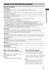
... displayed. Error Code 32 None of the acceptable range. Warning 41 The sound input from the optimizer microphone is connected properly but the error code appears, the optimizer microphone cable may vary. Warning 42 The volume of the receiver is out of the speakers were detected. Warning 43 The distance and position...
... displayed. Error Code 32 None of the acceptable range. Warning 41 The sound input from the optimizer microphone is connected properly but the error code appears, the optimizer microphone cable may vary. Warning 42 The volume of the receiver is out of the speakers were detected. Warning 43 The distance and position...

