
Limited Warranty (US Only)
Page 1
...not contained in exchange for your unit. A dated purchase receipt is valid only in material or workmanship during service and Sony will supply new or refurbished replacement parts in the Product; For specific instructions on how to obtain warranty service for parts...with a new or refurbished product. 4-557-173-03 General Stereo/Hifi Components/Tape Decks ® CD Players/Mini Disc Players/Audio Systems Hifi Audio LIMITED WARRANTY (U.S. This Limited Warranty covers only the hardware components packaged with new or refurbished product, product determined to commercial use ; ...
...not contained in exchange for your unit. A dated purchase receipt is valid only in material or workmanship during service and Sony will supply new or refurbished replacement parts in the Product; For specific instructions on how to obtain warranty service for parts...with a new or refurbished product. 4-557-173-03 General Stereo/Hifi Components/Tape Decks ® CD Players/Mini Disc Players/Audio Systems Hifi Audio LIMITED WARRANTY (U.S. This Limited Warranty covers only the hardware components packaged with new or refurbished product, product determined to commercial use ; ...
Operating Instructions
Page 6
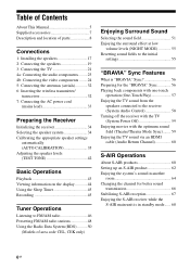
...the TV 21 4a: Connecting the audio components.........23 4b: Connecting the video components ........24 5: Connecting the antennas (aerials 32 6: Inserting the wireless transmitter/ transceiver 32 7: Connecting the AC power cord (mains lead 33 Preparing the Receiver Initializing the receiver 34 Selecting the speaker system 34 Calibrating... for the "BRAVIA" Sync 56 Playing back components with one-touch operation (One-Touch Play 57 Enjoying the TV sound from the speakers connected to the receiver (System Audio Control 58 Turning off the receiver with the TV (System Power Off 59 Enjoying...
...the TV 21 4a: Connecting the audio components.........23 4b: Connecting the video components ........24 5: Connecting the antennas (aerials 32 6: Inserting the wireless transmitter/ transceiver 32 7: Connecting the AC power cord (mains lead 33 Preparing the Receiver Initializing the receiver 34 Selecting the speaker system 34 Calibrating... for the "BRAVIA" Sync 56 Playing back components with one-touch operation (One-Touch Play 57 Enjoying the TV sound from the speakers connected to the receiver (System Audio Control 58 Turning off the receiver with the TV (System Power Off 59 Enjoying...

Operating Instructions
Page 7
... 93 Troubleshooting 95 Specifications 101 Index 103 • Remote commander (1) - Advanced Operations Switching between digital and analog audio (INPUT MODE 69 Enjoying the sound/images from other inputs 69 Enjoying sound/images from the components connected to the DIGITAL MEDIA PORT 71 Using a bi-amplifier connection 71 Using the setting menu 72...
... 93 Troubleshooting 95 Specifications 101 Index 103 • Remote commander (1) - Advanced Operations Switching between digital and analog audio (INPUT MODE 69 Enjoying the sound/images from other inputs 69 Enjoying sound/images from the components connected to the DIGITAL MEDIA PORT 71 Using a bi-amplifier connection 71 Using the setting menu 72...

Operating Instructions
Page 9
... is set to "ANALOG" or no digital signals are detected when INPUT MODE is set to "AUTO" and the source signal is selected and the Audio Return Channel (ARC) signals are connected. Indicator and explanation D ARC Lights up when INPUT MODE is set to "AUTO" (page 69). I SP A/SP B/SP A B ... IIz Dolby Pro Logic Dolby Pro Logic II Dolby Pro Logic IIx Dolby Pro Logic IIz Note These indicators may not light up when the receiver recognizes a component connected via an HDMI IN jack (page 24). OPT Lights up when DTS Neo:6 Cinema/Music decoder is output from the SUBWOOFER jack. ...
... is set to "ANALOG" or no digital signals are detected when INPUT MODE is set to "AUTO" and the source signal is selected and the Audio Return Channel (ARC) signals are connected. Indicator and explanation D ARC Lights up when INPUT MODE is set to "AUTO" (page 69). I SP A/SP B/SP A B ... IIz Dolby Pro Logic Dolby Pro Logic II Dolby Pro Logic IIx Dolby Pro Logic IIz Note These indicators may not light up when the receiver recognizes a component connected via an HDMI IN jack (page 24). OPT Lights up when DTS Neo:6 Cinema/Music decoder is output from the SUBWOOFER jack. ...

Operating Instructions
Page 10
... (based on the speaker settings). MEM Lights up when the receiver is activated. LH RH L R C SL SR S SBL SBR SB Front Left High Front Right High Front Left Front Right Center (monaural) Surround Left Surround Right Surround (monaural or the surround components obtained by Pro Logic processing) Surround Back Left Surround Back...
... (based on the speaker settings). MEM Lights up when the receiver is activated. LH RH L R C SL SR S SBL SBR SB Front Left High Front Right High Front Left Front Right Center (monaural) Surround Left Surround Right Surround (monaural or the surround components obtained by Pro Logic processing) Surround Back Left Surround Back...

Operating Instructions
Page 11
... 3 IN 3 IN 2 Y PB / CB PR / CR COMPONENT VIDEO AUDIO ASSIGNABLE (INPUT ONLY) OUT L R IN 1 MONITOR OUT DMPORT DC5V 0.7A MAX VIDEO IN VIDEO IN VIDEO OUT AUDIO IN AUDIO IN AUDIO IN AUDIO IN AUDIO OUT TV DIGITAL (ASSIGNABLE) IN OPTICAL SAT/ CATV IN OPTICAL VIDEO IN VIDEO OUT BD DVD IN IN COAXIAL AUDIO MONITOR IN AUDIO OUT SURROUND BACK/ FRONT HIGH/ BI-AMP...
... 3 IN 3 IN 2 Y PB / CB PR / CR COMPONENT VIDEO AUDIO ASSIGNABLE (INPUT ONLY) OUT L R IN 1 MONITOR OUT DMPORT DC5V 0.7A MAX VIDEO IN VIDEO IN VIDEO OUT AUDIO IN AUDIO IN AUDIO IN AUDIO IN AUDIO OUT TV DIGITAL (ASSIGNABLE) IN OPTICAL SAT/ CATV IN OPTICAL VIDEO IN VIDEO OUT BD DVD IN IN COAXIAL AUDIO MONITOR IN AUDIO OUT SURROUND BACK/ FRONT HIGH/ BI-AMP...

Operating Instructions
Page 12
...MONITOR OUT jack to operate. E Video signal section* The image quality depends on the connecting jack. F SPEAKERS section (page 19) Remote commander You can use the supplied remote to operate the receiver and to control the Sony audio/video components that the remote is assigned to... a TV (page 21, 24). BD DVD SAT/ CATV TV VIDEO 1 VIDEO 2 SA-CD/ CD DMPORT TUNER HDMI 1 HDMI 2 HDMI 3 HDMI 4 ql qk 1 ...
...MONITOR OUT jack to operate. E Video signal section* The image quality depends on the connecting jack. F SPEAKERS section (page 19) Remote commander You can use the supplied remote to operate the receiver and to control the Sony audio/video components that the remote is assigned to... a TV (page 21, 24). BD DVD SAT/ CATV TV VIDEO 1 VIDEO 2 SA-CD/ CD DMPORT TUNER HDMI 1 HDMI 2 HDMI 3 HDMI 4 ql qk 1 ...
Operating Instructions
Page 13
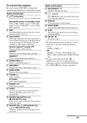
.... c)Press SHIFT (V) then only press this button. The buttons are initial assigned to control the receiver. number 5, VIDEO 1 -N - continued 13GB To control the receiver Be sure to press AMP (C) to change the remote button function to control Sony components. V SHIFT The button lights up and activates the buttons with pink printing. Name and function A ?/1b...
.... c)Press SHIFT (V) then only press this button. The buttons are initial assigned to control the receiver. number 5, VIDEO 1 -N - continued 13GB To control the receiver Be sure to press AMP (C) to change the remote button function to control Sony components. V SHIFT The button lights up and activates the buttons with pink printing. Name and function A ?/1b...

Operating Instructions
Page 14
...Follow the operation guide to the previous TV menu. ca)/C (RM-AAP050 only) In text mode: Selects the next or previous page. number 5, VIDEO 1 -N - D Numeric buttons (number 5a)) Selects the TV channels. -/--, >10 Selects the channel entry mode. I MENU/HOME Displays the TV...guide. To control a Sony TV Press TV (W), then press the yellow printing button to a quiz). Name and function T DISPLAY (RM-AAP049 only) Selects information of AV ?/1 (B) changes automatically each time you press ?/1 (A) and AV ?/1 (B) simultaneously, the receiver and connected components will turn off the ...
...Follow the operation guide to the previous TV menu. ca)/C (RM-AAP050 only) In text mode: Selects the next or previous page. number 5, VIDEO 1 -N - D Numeric buttons (number 5a)) Selects the TV channels. -/--, >10 Selects the channel entry mode. I MENU/HOME Displays the TV...guide. To control a Sony TV Press TV (W), then press the yellow printing button to a quiz). Name and function T DISPLAY (RM-AAP049 only) Selects information of AV ?/1 (B) changes automatically each time you press ?/1 (A) and AV ?/1 (B) simultaneously, the receiver and connected components will turn off the ...

Operating Instructions
Page 15
Search Search forward, forward, backward backward Play Play Pause Pause Stop Stop Side A, Bg) - Enter Select - To control other Sony components Name Blu-ray Satellite disc, DVD tuner player VCR PSX B AV ?/1b) D Numeric buttonsa)c) -/--c), >10c) Power Channel Clear ENTERc) F Color buttons H TOOLS/ OPTIONS I MENU/HOME J ./>k) ...
Search Search forward, forward, backward backward Play Play Pause Pause Stop Stop Side A, Bg) - Enter Select - To control other Sony components Name Blu-ray Satellite disc, DVD tuner player VCR PSX B AV ?/1b) D Numeric buttonsa)c) -/--c), >10c) Power Channel Clear ENTERc) F Color buttons H TOOLS/ OPTIONS I MENU/HOME J ./>k) ...

Operating Instructions
Page 16
... work depending on the model. • The above operation may not be cleared. Observe the correct polarity when installing batteries. number 5, VIDEO 1 -N - k)This button is intended to avoid possible damage from battery leakage and corrosion. • When you replace the batteries,...area code U2 only) or RM-AAP050 (Models of AV ?/1 (B) changes automatically each time you press ?/1 (A) and AV ?/1 (B) simultaneously, the receiver and connected components will turn off (SYSTEM STANDBY). a)The following buttons have tactile dots. PRESET +, TV CH + (RM-AAP049 only), PROG + (RM-AAP050 only...
... work depending on the model. • The above operation may not be cleared. Observe the correct polarity when installing batteries. number 5, VIDEO 1 -N - k)This button is intended to avoid possible damage from battery leakage and corrosion. • When you replace the batteries,...area code U2 only) or RM-AAP050 (Models of AV ?/1 (B) changes automatically each time you press ?/1 (A) and AV ?/1 (B) simultaneously, the receiver and connected components will turn off (SYSTEM STANDBY). a)The following buttons have tactile dots. PRESET +, TV CH + (RM-AAP049 only), PROG + (RM-AAP050 only...

Operating Instructions
Page 20
...using bi-amplifier connection (page 20). You can select the front speaker system you want using the SPEAKERS button on the receiver (page 34). • If you are not using surround back speaker or front high speakers, you have an additional front.../ CB PR / CR COMPONENT VIDEO AUDIO ASSIGNABLE (INPUT ONLY) OUT L R IN 1 MONITOR OUT DMPORT DC5V 0.7A MAX VIDEO IN VIDEO IN VIDEO OUT AUDIO IN AUDIO IN AUDIO IN AUDIO IN AUDIO OUT TV DIGITAL (ASSIGNABLE) IN OPTICAL SAT/ CATV IN OPTICAL VIDEO IN VIDEO OUT BD DVD IN IN COAXIAL AUDIO MONITOR IN AUDIO OUT SURROUND BACK/ FRONT HIGH...
...using bi-amplifier connection (page 20). You can select the front speaker system you want using the SPEAKERS button on the receiver (page 34). • If you are not using surround back speaker or front high speakers, you have an additional front.../ CB PR / CR COMPONENT VIDEO AUDIO ASSIGNABLE (INPUT ONLY) OUT L R IN 1 MONITOR OUT DMPORT DC5V 0.7A MAX VIDEO IN VIDEO IN VIDEO OUT AUDIO IN AUDIO IN AUDIO IN AUDIO IN AUDIO OUT TV DIGITAL (ASSIGNABLE) IN OPTICAL SAT/ CATV IN OPTICAL VIDEO IN VIDEO OUT BD DVD IN IN COAXIAL AUDIO MONITOR IN AUDIO OUT SURROUND BACK/ FRONT HIGH...
Operating Instructions
Page 21
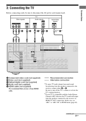
...CENTER L SPEAKERS SURROUND R L FRONT A R L A Component video cord (not supplied) B Video cord (not supplied) C Optical digital cord (not supplied) D Audio cord (not supplied) E HDMI cable (not supplied) We recommend that you use a Sony HDMI cable. continued 21GB Recommended connection Alternative connection a)To ...enjoy TV multi channel surround sound broadcasting from the speakers connected to the receiver via HDMI TV OUT connection. b)If your TV is compatible with the Audio Return ...
...CENTER L SPEAKERS SURROUND R L FRONT A R L A Component video cord (not supplied) B Video cord (not supplied) C Optical digital cord (not supplied) D Audio cord (not supplied) E HDMI cable (not supplied) We recommend that you use a Sony HDMI cable. continued 21GB Recommended connection Alternative connection a)To ...enjoy TV multi channel surround sound broadcasting from the speakers connected to the receiver via HDMI TV OUT connection. b)If your TV is compatible with the Audio Return ...

Operating Instructions
Page 22
...if you connect recording components. • Depending on the status of the connection between the TV and the antenna (aerial), the image on the receiver when the video and audio signals of video signals" (page 31). 22GB Unless the power is turned on, neither video nor audio signals will be ...transmitted. • Connect image display components such as a TV monitor or a projector to a ...
...if you connect recording components. • Depending on the status of the connection between the TV and the antenna (aerial), the image on the receiver when the video and audio signals of video signals" (page 31). 22GB Unless the power is turned on, neither video nor audio signals will be ...transmitted. • Connect image display components such as a TV monitor or a projector to a ...

Operating Instructions
Page 23
Connections 4a: Connecting the audio components The following illustration shows how to the receiver. 23GB Super Audio TV* CD player, CD player, CD recorder A B EZW-T100 ANTENNA AM IN 3 IN 2 Y PB / CB PR / CR COMPONENT VIDEO AUDIO ASSIGNABLE (INPUT ONLY) OUT L R IN 1 MONITOR OUT DMPORT DC5V 0.7A MAX VIDEO IN VIDEO IN VIDEO OUT AUDIO IN AUDIO IN AUDIO IN AUDIO IN AUDIO OUT TV DIGITAL...
Connections 4a: Connecting the audio components The following illustration shows how to the receiver. 23GB Super Audio TV* CD player, CD player, CD recorder A B EZW-T100 ANTENNA AM IN 3 IN 2 Y PB / CB PR / CR COMPONENT VIDEO AUDIO ASSIGNABLE (INPUT ONLY) OUT L R IN 1 MONITOR OUT DMPORT DC5V 0.7A MAX VIDEO IN VIDEO IN VIDEO OUT AUDIO IN AUDIO IN AUDIO IN AUDIO IN AUDIO OUT TV DIGITAL...

Operating Instructions
Page 24
... have HDMI jacks. If you connect your video components according to the table below. Colour (x.v. HDMI features • A digital audio signals transmitted by HDMI can be output from other inputs" (page 69). 4b: Connecting the video components Components to be connected Connect your video components via the receiver. Tip All the digital audio jacks are being output to disconnect the...
... have HDMI jacks. If you connect your video components according to the table below. Colour (x.v. HDMI features • A digital audio signals transmitted by HDMI can be output from other inputs" (page 69). 4b: Connecting the video components Components to be connected Connect your video components via the receiver. Tip All the digital audio jacks are being output to disconnect the...

Operating Instructions
Page 25
...COAXIAL AUDIO MONITOR IN AUDIO OUT SURROUND BACK/ FRONT HIGH/ BI-AMP/ FRONT B R SA-CD/CD/CD-R TV SAT/CATV BD VIDEO 1 SUBWOOFER IN 2 IN 1 HDMI ASSIGNABLE (INPUT ONLY) TV OUT ARC CENTER L SPEAKERS SURROUND R L FRONT A R L A A HDMI cable (not supplied) We recommend that it can use a Sony HDMI...that you use the button to the receiver. Notes • Be sure to change the initial setting of TV to control your components. For details, see "Naming inputs" (page 44). continued 25GB Audio/video signals TV, etc.* * See page 21 for the audio connection of the HDMI 1-4 input ...
...COAXIAL AUDIO MONITOR IN AUDIO OUT SURROUND BACK/ FRONT HIGH/ BI-AMP/ FRONT B R SA-CD/CD/CD-R TV SAT/CATV BD VIDEO 1 SUBWOOFER IN 2 IN 1 HDMI ASSIGNABLE (INPUT ONLY) TV OUT ARC CENTER L SPEAKERS SURROUND R L FRONT A R L A A HDMI cable (not supplied) We recommend that it can use a Sony HDMI...that you use the button to the receiver. Notes • Be sure to change the initial setting of TV to control your components. For details, see "Naming inputs" (page 44). continued 25GB Audio/video signals TV, etc.* * See page 21 for the audio connection of the HDMI 1-4 input ...

Operating Instructions
Page 26
Notes on the receiver when video and audio signals of player may not be displayed properly. • Sony recommends that are not output. • Audio signals (sampling frequency, bit length, etc.) transmitted from an HDMI jack may not support Audio Return Channel (ARC). &#...audio cords or digital connecting cords, then set "PASS THRU" to "OFF", video and audio signals will not output from the TV speaker. • DSD signals of Super Audio CD are being output to a TV through this case, check the specification of the connected component. • Be sure to "AMP". In this receiver...
Notes on the receiver when video and audio signals of player may not be displayed properly. • Sony recommends that are not output. • Audio signals (sampling frequency, bit length, etc.) transmitted from an HDMI jack may not support Audio Return Channel (ARC). &#...audio cords or digital connecting cords, then set "PASS THRU" to "OFF", video and audio signals will not output from the TV speaker. • DSD signals of Super Audio CD are being output to a TV through this case, check the specification of the connected component. • Be sure to "AMP". In this receiver...

Operating Instructions
Page 27
... 3 IN 3 IN 2 Y PB / CB PR / CR COMPONENT VIDEO AUDIO ASSIGNABLE (INPUT ONLY) OUT L R IN 1 MONITOR OUT DMPORT DC5V 0.7A MAX VIDEO IN VIDEO IN VIDEO OUT AUDIO IN AUDIO IN AUDIO IN AUDIO IN AUDIO OUT TV DIGITAL (ASSIGNABLE) IN OPTICAL SAT/ CATV IN OPTICAL VIDEO IN VIDEO OUT BD DVD IN IN COAXIAL AUDIO MONITOR IN AUDIO OUT SURROUND BACK/ FRONT HIGH/ BI-AMP...
... 3 IN 3 IN 2 Y PB / CB PR / CR COMPONENT VIDEO AUDIO ASSIGNABLE (INPUT ONLY) OUT L R IN 1 MONITOR OUT DMPORT DC5V 0.7A MAX VIDEO IN VIDEO IN VIDEO OUT AUDIO IN AUDIO IN AUDIO IN AUDIO IN AUDIO OUT TV DIGITAL (ASSIGNABLE) IN OPTICAL SAT/ CATV IN OPTICAL VIDEO IN VIDEO OUT BD DVD IN IN COAXIAL AUDIO MONITOR IN AUDIO OUT SURROUND BACK/ FRONT HIGH/ BI-AMP...

Operating Instructions
Page 28
... so that it can be sure to the COMPONENT VIDEO IN 1 or IN 3 jacks, set "A. ASSIGN" in the VIDEO menu (page 69). • To input multi channel digital audio from the DVD player or DVD recorder, set the digital audio output setting on the receiver's display. If you connect a component equipped with the DVD player or DVD...
... so that it can be sure to the COMPONENT VIDEO IN 1 or IN 3 jacks, set "A. ASSIGN" in the VIDEO menu (page 69). • To input multi channel digital audio from the DVD player or DVD recorder, set the digital audio output setting on the receiver's display. If you connect a component equipped with the DVD player or DVD...


