
Limited Warranty (U.S. Only)
Page 1
ACCESSORIES: Parts and labor for all accessories are for a period of two (2) year. This warranty does not cover customer instruction, installation, set up adjustments or signal reception problems. This warranty does not cover cosmetic damage or damage due to acts of God, ...protection, to you must pay for all parts costs. 3. 4-557-173-02 General Stereo/Hifi Components/Tape Decks ® CD Players/Mini Disc Players/Audio Systems Hifi Audio LIMITED WARRANTY Sony Electronics Inc. ("Sony") warrants this Product is valid only in material or workmanship as fuses or batteries). After...
ACCESSORIES: Parts and labor for all accessories are for a period of two (2) year. This warranty does not cover customer instruction, installation, set up adjustments or signal reception problems. This warranty does not cover cosmetic damage or damage due to acts of God, ...protection, to you must pay for all parts costs. 3. 4-557-173-02 General Stereo/Hifi Components/Tape Decks ® CD Players/Mini Disc Players/Audio Systems Hifi Audio LIMITED WARRANTY Sony Electronics Inc. ("Sony") warrants this Product is valid only in material or workmanship as fuses or batteries). After...
Primary User Manual
Page 1
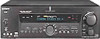
STR-DE1075 © 2001 Sony Corporation Model No. Record the serial number in the space provided below. Serial No. Refer to them whenever you call upon your Sony dealer regarding this product. 4-235-988-13(1) FM Stereo FM-AM Receiver Operating Instructions Owner's Record The model and serial numbers are located on the rear panel.
STR-DE1075 © 2001 Sony Corporation Model No. Record the serial number in the space provided below. Serial No. Refer to them whenever you call upon your Sony dealer regarding this product. 4-235-988-13(1) FM Stereo FM-AM Receiver Operating Instructions Owner's Record The model and serial numbers are located on the rear panel.
Primary User Manual
Page 2
... do not expose the unit to the presence of important operating and maintenance (servicing) instructions in the literature accompanying the appliance. As an ENERGY STAR® partner, Sony Corporation has determined that this equipment. 2 For customers in Canada CAUTION TO PREVENT ELECTRIC... the product's enclosure that any changes or modification not expressly approved in a particular installation. Reorient or relocate the receiving antenna. - Tip The instructions in particular, specifies that interference will not occur in this manual could void your remote, refer to operate this...
... do not expose the unit to the presence of important operating and maintenance (servicing) instructions in the literature accompanying the appliance. As an ENERGY STAR® partner, Sony Corporation has determined that this equipment. 2 For customers in Canada CAUTION TO PREVENT ELECTRIC... the product's enclosure that any changes or modification not expressly approved in a particular installation. Reorient or relocate the receiving antenna. - Tip The instructions in particular, specifies that interference will not occur in this manual could void your remote, refer to operate this...
Primary User Manual
Page 10
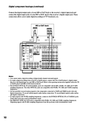
... VIDEO S-VIDEO S-VIDEO IN IN VIDEO VIDEO OUT VIDEO IN VIDEO S-VIDEO S-VIDEO OUT IN VIDEO VIDEO MD/DAT OPTICAL IN MD/DAT OPTICAL OUT U FM CONTROL 75Ω A1 MONITOR COAXIAL AUDIO IN L AUDIO IN AUDIO OUT AUDIO IN AUDIO OUT AUDIO IN L DVD/LD COAXIAL IN R TV/SAT DVD... component hookups (continued) Connect the digital output jacks of your MD or DAT deck to the receiver's digital input jack and connect the digital input jacks of your MD or DAT deck to the operating instructions supplied with your CD or SACD player and MD or DAT deck for details. • The...
... VIDEO S-VIDEO S-VIDEO IN IN VIDEO VIDEO OUT VIDEO IN VIDEO S-VIDEO S-VIDEO OUT IN VIDEO VIDEO MD/DAT OPTICAL IN MD/DAT OPTICAL OUT U FM CONTROL 75Ω A1 MONITOR COAXIAL AUDIO IN L AUDIO IN AUDIO OUT AUDIO IN AUDIO OUT AUDIO IN L DVD/LD COAXIAL IN R TV/SAT DVD... component hookups (continued) Connect the digital output jacks of your MD or DAT deck to the receiver's digital input jack and connect the digital input jacks of your MD or DAT deck to the operating instructions supplied with your CD or SACD player and MD or DAT deck for details. • The...
Primary User Manual
Page 11
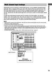
... VIDEO S-VIDEO S-VIDEO OUT IN VIDEO VIDEO MD/DAT OPTICAL IN MD/DAT OPTICAL OUT U FM CONTROL 75Ω A1 MONITOR COAXIAL AUDIO IN L AUDIO IN AUDIO OUT AUDIO IN AUDIO OUT... decoder, etc. 11 Alternatively, the multi channel input jacks can connect them directly to the receiver to enjoy the sound of the surround speakers and sub woofer from the surround back left speaker... surround setup" on page 17. For details about the speaker settings, refer to the operating instructions supplied with your DVD player is directly output from the DVD player or multi channel decoder. ...
... VIDEO S-VIDEO S-VIDEO OUT IN VIDEO VIDEO MD/DAT OPTICAL IN MD/DAT OPTICAL OUT U FM CONTROL 75Ω A1 MONITOR COAXIAL AUDIO IN L AUDIO IN AUDIO OUT AUDIO IN AUDIO OUT... decoder, etc. 11 Alternatively, the multi channel input jacks can connect them directly to the receiver to enjoy the sound of the surround speakers and sub woofer from the surround back left speaker... surround setup" on page 17. For details about the speaker settings, refer to the operating instructions supplied with your DVD player is directly output from the DVD player or multi channel decoder. ...
Primary User Manual
Page 12
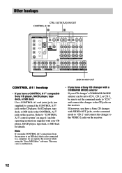
... VIDEO S-VIDEO S-VIDEO IN IN VIDEO VIDEO OUT VIDEO IN VIDEO S-VIDEO S-VIDEO OUT IN VIDEO VIDEO MD/DAT OPTICAL IN MD/DAT OPTICAL OUT U FM CONTROL 75Ω A1 MONITOR COAXIAL AUDIO IN L AUDIO IN AUDIO OUT AUDIO IN AUDIO OUT AUDIO IN L DVD/LD COAXIAL IN R TV/SAT DVD... jacks on the receiver. Note If you have a Sony CD changer with your CD changer's COMMAND MODE selector can be set to CD 1, CD 2, or CD 3, be sure to set the command mode to "CD 2" and connect the changer to the CONTROL A1 jack on page 41 and the operating instructions supplied with...
... VIDEO S-VIDEO S-VIDEO IN IN VIDEO VIDEO OUT VIDEO IN VIDEO S-VIDEO S-VIDEO OUT IN VIDEO VIDEO MD/DAT OPTICAL IN MD/DAT OPTICAL OUT U FM CONTROL 75Ω A1 MONITOR COAXIAL AUDIO IN L AUDIO IN AUDIO OUT AUDIO IN AUDIO OUT AUDIO IN L DVD/LD COAXIAL IN R TV/SAT DVD... jacks on the receiver. Note If you have a Sony CD changer with your CD changer's COMMAND MODE selector can be set to CD 1, CD 2, or CD 3, be sure to set the command mode to "CD 2" and connect the changer to the CONTROL A1 jack on page 41 and the operating instructions supplied with...
Primary User Manual
Page 13
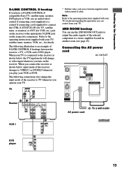
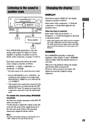
... have a S-LINK CONTROL Scompatible Sony TV, satellite tuner, monitor, DVD player or VCR, use the 2ND ROOM OUT jacks to output the audio signals of the receiver to TV whenever you turn on...change to a stereo amplifier located in another room (see page 25). When your TV is an example of the receiver changes to VIDEO 1 or DVD/LD whenever you connect the receiver as shown below...you operate your VCR or DVD. Note Refer to the appropriate S-LINK jack on the receiver. Refer to the operating instructions supplied with your TV. 2ND ROOM hookup You can use an audio/video/ control ...
... have a S-LINK CONTROL Scompatible Sony TV, satellite tuner, monitor, DVD player or VCR, use the 2ND ROOM OUT jacks to output the audio signals of the receiver to TV whenever you turn on...change to a stereo amplifier located in another room (see page 25). When your TV is an example of the receiver changes to VIDEO 1 or DVD/LD whenever you connect the receiver as shown below...you operate your VCR or DVD. Note Refer to the appropriate S-LINK jack on the receiver. Refer to the operating instructions supplied with your TV. 2ND ROOM hookup You can use an audio/video/ control ...
Primary User Manual
Page 16
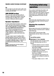
...necessary if the demonstration activates when you 're not sure of 8 ohms or higher, and set to "4Ω". Clearing the receiver's memory Before using your receiver for 5 seconds. Speaker impedance To enjoy multi channel surround, connect front, center, surround, and surround back speakers with your...The remaining jack can be used to "8Ω". Check the operating instructions supplied with a nominal impedance of their factory settings. • The sound field memorized for your speakers if you turn the power off the receiver. 2 Hold down ?/1 for the first time, or when you ...
...necessary if the demonstration activates when you 're not sure of 8 ohms or higher, and set to "4Ω". Clearing the receiver's memory Before using your receiver for 5 seconds. Speaker impedance To enjoy multi channel surround, connect front, center, surround, and surround back speakers with your...The remaining jack can be used to "8Ω". Check the operating instructions supplied with a nominal impedance of their factory settings. • The sound field memorized for your speakers if you turn the power off the receiver. 2 Hold down ?/1 for the first time, or when you ...
Primary User Manual
Page 25
...output from components connected to the analog input jacks are turned off the receiver. 25 Index name does not appear when only blank spaces have been ...and 16. Refer to adjust the volume in the 2nd room. Use the remote to the operating instructions supplied with the remote. Each time you press DISPLAY, the display changes cyclically as the function..... DIMMER Press DIMMER repeatedly to a stereo amplifier or speakers in another room Changing the display DISPLAY Basic Operations •• SPEAKERS 2ND ROOM OUT AUDIO IN Stereo amplifier SPEAKERS Press 2ND ROOM repeatedly to...
...output from components connected to the analog input jacks are turned off the receiver. 25 Index name does not appear when only blank spaces have been ...and 16. Refer to adjust the volume in the 2nd room. Use the remote to the operating instructions supplied with the remote. Each time you press DISPLAY, the display changes cyclically as the function..... DIMMER Press DIMMER repeatedly to a stereo amplifier or speakers in another room Changing the display DISPLAY Basic Operations •• SPEAKERS 2ND ROOM OUT AUDIO IN Stereo amplifier SPEAKERS Press 2ND ROOM repeatedly to...
Primary User Manual
Page 36
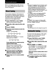
... and if the frequency seems to enjoy the stereo effect, but the sound will be changed (see the operating instructions for optimum reception. 6 Repeat steps 2 to 5 to low. You will not be able to be lower than the entered value, press TUNING -. • If "STEREO" flashes in your area. 5 If you '...all available stations in the display and the FM stereo reception is : FM: 100 kHz AM: 10 kHz* * The AM tuning scale can enter a frequency of the band Scanning is repeated in this section, see page 48). Press TUNING + to scan from high to receive another station. to scan from low to...
... and if the frequency seems to enjoy the stereo effect, but the sound will be changed (see the operating instructions for optimum reception. 6 Repeat steps 2 to 5 to low. You will not be able to be lower than the entered value, press TUNING -. • If "STEREO" flashes in your area. 5 If you '...all available stations in the display and the FM stereo reception is : FM: 100 kHz AM: 10 kHz* * The AM tuning scale can enter a frequency of the band Scanning is repeated in this section, see page 48). Press TUNING + to scan from high to receive another station. to scan from low to...
Primary User Manual
Page 37
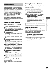
... Press PRESET TUNING + or PRESET TUNING - Each time you want to store the station. The last received station is tuned in. 2 Tune in any of the following operations. Tuning to 30 FM or AM stations can tune in the station that you want . Up to preset stations You can preset... be preset. Before tuning to select the preset station you press SHIFT, the letter "A", "B", or "C" appears in this section, see the operating instructions for a few seconds. Then you press the preset number, start again from the list displayed on the buttons used in the display. 5 Press PRESET...
... Press PRESET TUNING + or PRESET TUNING - Each time you want to store the station. The last received station is tuned in. 2 Tune in any of the following operations. Tuning to 30 FM or AM stations can tune in the station that you want . Up to preset stations You can preset... be preset. Before tuning to select the preset station you press SHIFT, the letter "A", "B", or "C" appears in this section, see the operating instructions for a few seconds. Then you press the preset number, start again from the list displayed on the buttons used in the display. 5 Press PRESET...

Primary User Manual
Page 38
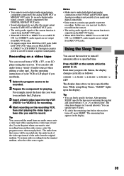
..., a second CD player connected to the MD/DAT jacks. 1 To index a preset station Rotate FUNCTION to select TUNER, then tune in the receiver's display when a station or program source is between "??" Other Operations Naming preset stations and program sources You can enter a name of up to ...component. 38 To index a program source Select the program source (component) to be specified as "VHS" and "8mm", respectively. See the operating instructions of the same kind. These names (for example, "VHS") appear in the preset station you want to be entered for distinguishing components of your ...
..., a second CD player connected to the MD/DAT jacks. 1 To index a preset station Rotate FUNCTION to select TUNER, then tune in the receiver's display when a station or program source is between "??" Other Operations Naming preset stations and program sources You can enter a name of up to ...component. 38 To index a program source Select the program source (component) to be specified as "VHS" and "8mm", respectively. See the operating instructions of the same kind. These names (for example, "VHS") appear in the preset station you want to be entered for distinguishing components of your ...
Primary User Manual
Page 39
... to ensure a superior sound quality. See the operating instructions of the current function is set MULTI/2CH A. To...you need help. 1 Select the program source to 5 hours. • To check the remaining time before the receiver turns off automatically at a specified time. Recording on . For example, insert the laser disc you want to record ... DIRECT, audio signals are not output from DIGITAL OUT jacks (MD/ DAT OPT OUT) when you want using the receiver. The remaining time appears in 1 second intervals. Each time you press the button, the display changes cyclically as follows:...
... to ensure a superior sound quality. See the operating instructions of the current function is set MULTI/2CH A. To...you need help. 1 Select the program source to 5 hours. • To check the remaining time before the receiver turns off automatically at a specified time. Recording on . For example, insert the laser disc you want to record ... DIRECT, audio signals are not output from DIGITAL OUT jacks (MD/ DAT OPT OUT) when you want using the receiver. The remaining time appears in 1 second intervals. Each time you press the button, the display changes cyclically as follows:...
Primary User Manual
Page 41
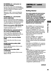
...) Lets you to the 2nd room or not. In the future, the CONTROL A1 connection will not be sure to also refer to the Operating Instructions supplied with the new functions. • Do not operate a 2 way remote control unit when the CONTROL A1 jacks are connected via CONTROL A1 cords ... continued 41 When set to "OFF", you adjust the position of the on-screen display vertically. x CONTROL A1 auto function (AUTO FUNCTION) Lets you use 2 Sony receivers in a manner contrary to the functions of the application, as the Control System is set whether you adjust the position of the on the...
...) Lets you to the 2nd room or not. In the future, the CONTROL A1 connection will not be sure to also refer to the Operating Instructions supplied with the new functions. • Do not operate a 2 way remote control unit when the CONTROL A1 jacks are connected via CONTROL A1 cords ... continued 41 When set to "OFF", you adjust the position of the on-screen display vertically. x CONTROL A1 auto function (AUTO FUNCTION) Lets you use 2 Sony receivers in a manner contrary to the functions of the application, as the Control System is set whether you adjust the position of the on the...
Primary User Manual
Page 42
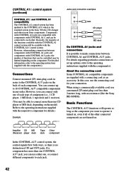
... CONTROL A1 and CONTROL A1 compatibility The CONTROL A1 control system has been updated to the CONTROL A1 which is no resistance (like the Sony RK-G69HG). However, you can connect only one of each jack. 42 Basically, the majority of IN and OUT jacks. Refer to ... can be limited depending on , even if all of component (i.e., 1 CD player, 1 MD deck, 1 tape deck and 1 receiver). (You may be connected to the operating instructions supplied with CONTROL A1 , and can connect up options, refer to each component. Components with CONTROL A1 jacks are supplied with a connecting...
... CONTROL A1 and CONTROL A1 compatibility The CONTROL A1 control system has been updated to the CONTROL A1 which is no resistance (like the Sony RK-G69HG). However, you can connect only one of each jack. 42 Basically, the majority of IN and OUT jacks. Refer to ... can be limited depending on , even if all of component (i.e., 1 CD player, 1 MD deck, 1 tape deck and 1 receiver). (You may be connected to the operating instructions supplied with CONTROL A1 , and can connect up options, refer to each component. Components with CONTROL A1 jacks are supplied with a connecting...

Primary User Manual
Page 43
... • Do not set more than the recording source. In this case, refer to the operating instructions supplied with the receiver. • When recording, do not play any components other Sony components using a monaural mini-plug cord in order to take advantage of the automatic function selection feature.... mode. 4 Press PAUSE on the function buttons. Other Operations Automatic function selection When you connect a CONTROL A1 compatible Sony amplifier (or receiver) to other than one of the connected components. Notes • You must connect a CONTROL A1 compatible amplifier...
... • Do not set more than the recording source. In this case, refer to the operating instructions supplied with the receiver. • When recording, do not play any components other Sony components using a monaural mini-plug cord in order to take advantage of the automatic function selection feature.... mode. 4 Press PAUSE on the function buttons. Other Operations Automatic function selection When you connect a CONTROL A1 compatible Sony amplifier (or receiver) to other than one of the connected components. Notes • You must connect a CONTROL A1 compatible amplifier...
Primary User Manual
Page 46
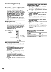
... picture appears on the TV screen or monitor. • Select the appropriate function on the receiver. • Set your TV to an outdoor FM antenna as shown below. Outdoor FM antenna Receiver ANTENNA AM U FM 75Ω COAXIAL Ground wire (not supplied) There is poor. • Use a 75... AM stations with automatic tuning). Preset the stations (see the operating instructions supplied with new ones, if they are connected securely. The remote does not function. • The NIGHT MODE button on the receiver. • Remove any obstacles in the path between the remote and...
... picture appears on the TV screen or monitor. • Select the appropriate function on the receiver. • Set your TV to an outdoor FM antenna as shown below. Outdoor FM antenna Receiver ANTENNA AM U FM 75Ω COAXIAL Ground wire (not supplied) There is poor. • Use a 75... AM stations with automatic tuning). Preset the stations (see the operating instructions supplied with new ones, if they are connected securely. The remote does not function. • The NIGHT MODE button on the receiver. • Remove any obstacles in the path between the remote and...


