
Limited Warranty (U.S. Only)
Page 1
... cover damage due to improper operation or maintenance, connection to improper voltage supply, or attempted repair by Sony to you must be defective, Sony will supply, at no charge, new or rebuilt replacements in material or workmanship as fuses or batteries). 4-557-173-02 General Stereo/Hifi Components/Tape Decks ® CD Players/Mini Disc Players/Audio Systems Hifi Audio LIMITED WARRANTY Sony Electronics Inc. ("Sony") warrants this Product is within...
... cover damage due to improper operation or maintenance, connection to improper voltage supply, or attempted repair by Sony to you must be defective, Sony will supply, at no charge, new or rebuilt replacements in material or workmanship as fuses or batteries). 4-557-173-02 General Stereo/Hifi Components/Tape Decks ® CD Players/Mini Disc Players/Audio Systems Hifi Audio LIMITED WARRANTY Sony Electronics Inc. ("Sony") warrants this Product is within...

Primary User Manual
Page 3
...The next time you turn the receiver on the power. Table of Contents Parts Identification Main unit 4 Hooking Up the Components Required cords 5 Antenna hookups 6 Audio component hookups 7 Video component hookups 8 Digital component hookups 9 Multi channel input hookups 11 Other hookups 12 Hooking Up and Setting Up the Speaker System Speaker system hookups 15 Performing initial setup operations ..... 16 Multi channel surround setup 17 Checking the connections 22 Basic Operations Selecting the component 23 Listening to the sound in another room 25 Changing the display 25 Enjoying...
...The next time you turn the receiver on the power. Table of Contents Parts Identification Main unit 4 Hooking Up the Components Required cords 5 Antenna hookups 6 Audio component hookups 7 Video component hookups 8 Digital component hookups 9 Multi channel input hookups 11 Other hookups 12 Hooking Up and Setting Up the Speaker System Speaker system hookups 15 Performing initial setup operations ..... 16 Multi channel surround setup 17 Checking the connections 22 Basic Operations Selecting the component 23 Listening to the sound in another room 25 Changing the display 25 Enjoying...
Primary User Manual
Page 5
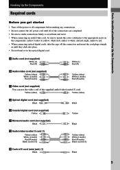
...; When connecting an audio/video cord, be sure to match the color-coded pins to the appropriate jacks on the components: yellow (video) to yellow; white (left, audio) to red. • When connecting optical digital cords, take the caps off the power to all of the supplied audio/video/control S cord. Parts Identification/Hooking Up the Components Hooking Up the Components Required cords Before you get started • Turn off the connectors and insert the cord plugs straight...
...; When connecting an audio/video cord, be sure to match the color-coded pins to the appropriate jacks on the components: yellow (video) to yellow; white (left, audio) to red. • When connecting optical digital cords, take the caps off the power to all of the supplied audio/video/control S cord. Parts Identification/Hooking Up the Components Hooking Up the Components Required cords Before you get started • Turn off the connectors and insert the cord plugs straight...
Primary User Manual
Page 8
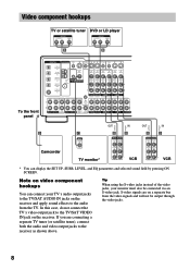
...'s audio output jacks to the TV/SAT AUDIO IN jacks on a separate bus from the TV. S-video signals are connecting a separate TV tuner (or satellite tuner), connect both the audio and video output jacks to the TV/SAT VIDEO IN jack on video component hookups You can display the SET UP, SURR, LEVEL, and EQ parameters and selected sound field by pressing ON SCREEN. Video component hookups TV or satellite tuner DVD or LD player OUTPUT AUDIO OUT R L VIDEO OUT OUTPUT AUDIO OUT R L VIDEO OUT B B To the front panel DIGITAL ANTENNA...
...'s audio output jacks to the TV/SAT AUDIO IN jacks on a separate bus from the TV. S-video signals are connecting a separate TV tuner (or satellite tuner), connect both the audio and video output jacks to the TV/SAT VIDEO IN jack on video component hookups You can display the SET UP, SURR, LEVEL, and EQ parameters and selected sound field by pressing ON SCREEN. Video component hookups TV or satellite tuner DVD or LD player OUTPUT AUDIO OUT R L VIDEO OUT OUTPUT AUDIO OUT R L VIDEO OUT B B To the front panel DIGITAL ANTENNA...
Primary User Manual
Page 9
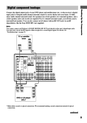
..."Troubleshooting" on page 44. continued 9 Note You cannot connect an LD player's DOLBY DIGITAL RF OUT jack directly to either coaxial or optical connections. For 6.1 channel surround sound, you will also need a surround back speaker. Hooking Up the Components Digital component hookups Connect the digital output jacks of your home. TV or satellite tuner OUTPUT VIDEO OUT OUTPUT DIGITAL OPTICAL AUDIO OUT L R D B DIGITAL ANTENNA CTRL S IN CTRL S STATUS IN CTRL S OUT CTRL S OUT DVD/LD OPTICAL IN AM TV/SAT OPTICAL IN S-VIDEO OUT VIDEO S-VIDEO IN VIDEO S-VIDEO IN VIDEO...
..."Troubleshooting" on page 44. continued 9 Note You cannot connect an LD player's DOLBY DIGITAL RF OUT jack directly to either coaxial or optical connections. For 6.1 channel surround sound, you will also need a surround back speaker. Hooking Up the Components Digital component hookups Connect the digital output jacks of your home. TV or satellite tuner OUTPUT VIDEO OUT OUTPUT DIGITAL OPTICAL AUDIO OUT L R D B DIGITAL ANTENNA CTRL S IN CTRL S STATUS IN CTRL S OUT CTRL S OUT DVD/LD OPTICAL IN AM TV/SAT OPTICAL IN S-VIDEO OUT VIDEO S-VIDEO IN VIDEO S-VIDEO IN VIDEO...
Primary User Manual
Page 11
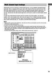
... using the connections described below, adjust the level of the DVD player's multi channel decoder. To fully enjoy multi channel surround sound, five speakers (two front speakers, two surround speakers, and a center speaker) and a sub woofer are required. Refer to the operating instructions supplied with your DVD player is equipped with multi channel input jacks. DIGITAL ANTENNA CTRL S IN CTRL S STATUS IN CTRL S OUT CTRL S OUT DVD/LD OPTICAL IN AM TV/SAT OPTICAL IN S-VIDEO OUT VIDEO S-VIDEO IN VIDEO S-VIDEO IN VIDEO OUT VIDEO IN VIDEO S-VIDEO S-VIDEO OUT IN VIDEO VIDEO...
... using the connections described below, adjust the level of the DVD player's multi channel decoder. To fully enjoy multi channel surround sound, five speakers (two front speakers, two surround speakers, and a center speaker) and a sub woofer are required. Refer to the operating instructions supplied with your DVD player is equipped with multi channel input jacks. DIGITAL ANTENNA CTRL S IN CTRL S STATUS IN CTRL S OUT CTRL S OUT DVD/LD OPTICAL IN AM TV/SAT OPTICAL IN S-VIDEO OUT VIDEO S-VIDEO IN VIDEO S-VIDEO IN VIDEO OUT VIDEO IN VIDEO S-VIDEO S-VIDEO OUT IN VIDEO VIDEO...
Primary User Manual
Page 13
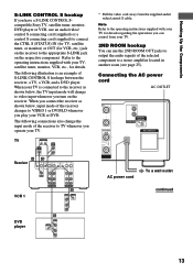
Hooking Up the Components S-LINK CONTROL S hookup If you have a S-LINK CONTROL Scompatible Sony TV, satellite tuner, monitor, DVD player or VCR, use the 2ND ROOM OUT jacks to output the audio signals of S-LINK CONTROL S hookups between the receiver, a TV, a VCR, and a DVD player. Connecting the AC power cord AC OUTLET ONT + L - The following connections also change to the operating instructions supplied with your VCR or DVD. Note Refer to video input whenever you turn on the receiver. The following illustration is...
Hooking Up the Components S-LINK CONTROL S hookup If you have a S-LINK CONTROL Scompatible Sony TV, satellite tuner, monitor, DVD player or VCR, use the 2ND ROOM OUT jacks to output the audio signals of S-LINK CONTROL S hookups between the receiver, a TV, a VCR, and a DVD player. Connecting the AC power cord AC OUTLET ONT + L - The following connections also change to the operating instructions supplied with your VCR or DVD. Note Refer to video input whenever you turn on the receiver. The following illustration is...
Primary User Manual
Page 16
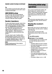
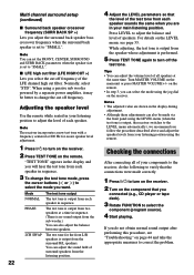
... initial setup operations Once you turn the power off the receiver. 2 Hold down ?/1 for each program source and preset stations are cleared. • The master volume is not necessary if the demonstration activates when you have hooked up while outputting the sound), check the connection (see page 3) and all of preset stations and program sources) are cleared. • All SET UP parameters are reset to "8Ω". The remaining jack can be used to connect...
... initial setup operations Once you turn the power off the receiver. 2 Hold down ?/1 for each program source and preset stations are cleared. • The master volume is not necessary if the demonstration activates when you have hooked up while outputting the sound), check the connection (see page 3) and all of preset stations and program sources) are cleared. • All SET UP parameters are reset to "8Ω". The remaining jack can be used to connect...
Primary User Manual
Page 21
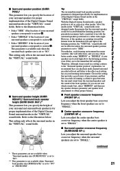
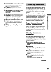
... best succeeds in the "VIRTUAL" sound fields were designed under the premise that you playback multi channel surround encoded software and listen to the effect each listening environment has many variables, like wall reflections, and you adjust the center speaker bass crossover frequency when the center speaker is set to "SMALL". With the Digital Cinema Sound modes, speaker position is designed specifically for implementation of the Digital Cinema Sound modes in the "VIRTUAL" sound fields. x Center speaker crossover frequency (CENTER...
... best succeeds in the "VIRTUAL" sound fields were designed under the premise that you playback multi channel surround encoded software and listen to the effect each listening environment has many variables, like wall reflections, and you adjust the center speaker bass crossover frequency when the center speaker is set to "SMALL". With the Digital Cinema Sound modes, speaker position is designed specifically for implementation of the Digital Cinema Sound modes in the "VIRTUAL" sound fields. x Center speaker crossover frequency (CENTER...
Primary User Manual
Page 22
... adjust the level of the LFE channel high cut filter. For details on the LEVEL menu, see "Troubleshooting" on the receiver. Turn MASTER VOLUME on the remote. Note The receiver incorporates a new test tone with a frequency centered at 800 Hz for the front L/R speakers is output, the receiver switches to the LEVEL menu automatically), we recommend you follow the procedure described above and adjust the speaker levels from each speaker in your listening position using a passive sub woofer powered by a separate power amplifier...
... adjust the level of the LFE channel high cut filter. For details on the LEVEL menu, see "Troubleshooting" on the receiver. Turn MASTER VOLUME on the remote. Note The receiver incorporates a new test tone with a frequency centered at 800 Hz for the front L/R speakers is output, the receiver switches to the LEVEL menu automatically), we recommend you follow the procedure described above and adjust the speaker levels from each speaker in your listening position using a passive sub woofer powered by a separate power amplifier...
Primary User Manual
Page 23
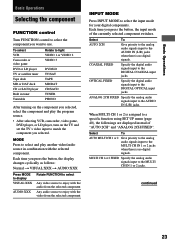
... TUNER PHONO After turning on the component you selected, select the component and play another video/audio source in combination with the video from the selected component INPUT MODE Press INPUT MODE to select the input mode for your digital components. MODE Press to select and play the program source. • After selecting VCR, camcorder, video game, DVD player, or LD player, turn on the TV and set the TV's video input to match the component you press the button, the input mode of "AUTO 2CH" and "ANALOG 2CH FIXED". Each time you want to use. Select...
... TUNER PHONO After turning on the component you selected, select the component and play another video/audio source in combination with the video from the selected component INPUT MODE Press INPUT MODE to select the input mode for your digital components. MODE Press to select and play the program source. • After selecting VCR, camcorder, video game, DVD player, or LD player, turn on the TV and set the TV's video input to match the component you press the button, the input mode of "AUTO 2CH" and "ANALOG 2CH FIXED". Each time you want to use. Select...
Primary User Manual
Page 24
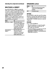
.... SPEAKERS switch Select ON OFF To Output the sound from the speakers connected to the MULTI CH IN 1 or 2 jacks or analog 2 channel input jacks. This mode is suitable for enjoying high quality analog source. OFF" lights up . When set to MULTI CH 1 or 2 DIRECT, you can be adjusted when set to turn the volume up in the display. Selecting the component (continued) MULTI/2CH A. MUTING Press MUTING to the MULTI CH IN 1 or 2 jacks. Select To MULTI CH 1 or 2 DIRECT Enjoy the audio source connected...
.... SPEAKERS switch Select ON OFF To Output the sound from the speakers connected to the MULTI CH IN 1 or 2 jacks or analog 2 channel input jacks. This mode is suitable for enjoying high quality analog source. OFF" lights up . When set to MULTI CH 1 or 2 DIRECT, you can be adjusted when set to turn the volume up in the display. Selecting the component (continued) MULTI/2CH A. MUTING Press MUTING to the MULTI CH IN 1 or 2 jacks. Select To MULTI CH 1 or 2 DIRECT Enjoy the audio source connected...
Primary User Manual
Page 25
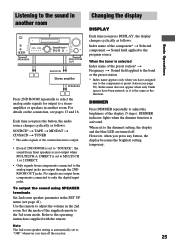
...: SOURCE* t TAPE t MD/DAT t CD/SACD t TUNER * The audio signals of the preset station* t Frequency t Sound field applied to the analog input jacks are turned off the receiver. 25 When set to MULTI CH 1 or 2 DIRECT. • Only signals from components connected to the band or the preset station * Index name appears only when you turn off . Use the remote to the operating instructions supplied with the remote. To output the sound using SPEAKER terminals Set 2nd room speaker parameter in the SET UP menu (see...
...: SOURCE* t TAPE t MD/DAT t CD/SACD t TUNER * The audio signals of the preset station* t Frequency t Sound field applied to the analog input jacks are turned off the receiver. 25 When set to MULTI CH 1 or 2 DIRECT. • Only signals from components connected to the band or the preset station * Index name appears only when you turn off . Use the remote to the operating instructions supplied with the remote. To output the sound using SPEAKER terminals Set 2nd room speaker parameter in the SET UP menu (see...
Primary User Manual
Page 26
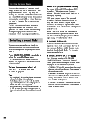
... SOUND FIELD MODE repeatedly to select the sound field you want by changing the various surround parameters. Software with 2 channel audio signals is decoded with multi channel surround audio signals is one of an actual cinema cutting studio in the display. You can also customize the sound fields to obtain the sound you want . Dolby Digital discs are labeled with the logo, and Dolby Surround encoded programs are labeled with the logo. • When sound signals...
... SOUND FIELD MODE repeatedly to select the sound field you want by changing the various surround parameters. Software with 2 channel audio signals is decoded with multi channel surround audio signals is one of an actual cinema cutting studio in the display. You can also customize the sound fields to obtain the sound you want . Dolby Digital discs are labeled with the logo, and Dolby Surround encoded programs are labeled with the logo. • When sound signals...
Primary User Manual
Page 31
..., center, surround, and surround back speakers, you customize a sound field, the changes are input. qj ;: Lights up when sleep timer is displayed. 3 Press the cursor buttons ( or ) to select the parameter you want to adjust. 4 Turn the jog dial to OFF. The settings are input. qa SLEEP: Lights up when Dolby Digital signals are stored individually for tuner operations. qg DTS: Lights up when the audio signal is entered automatically. qd EQ: Lights up when using the receiver...
..., center, surround, and surround back speakers, you customize a sound field, the changes are input. qj ;: Lights up when sleep timer is displayed. 3 Press the cursor buttons ( or ) to select the parameter you want to adjust. 4 Turn the jog dial to OFF. The settings are input. qa SLEEP: Lights up when Dolby Digital signals are stored individually for tuner operations. qg DTS: Lights up when the audio signal is entered automatically. qd EQ: Lights up when using the receiver...
Primary User Manual
Page 34
... dynamic range of treble. To turn on the equalizer. RANGE COMP.) Lets you want . We recommend using the EQ parameters, the settings are stored individually for each sound field. 1 Start playing a program source encoded with multi channel surround sound. 2 Press EQ. Note Dynamic range compression is entered automatically. The button lights up when the equalizer is displayed. 3 Press the cursor buttons ( or ) to select the parameter (gain (dB), frequency (Hz)) you want to adjust. 4 Turn...
... dynamic range of treble. To turn on the equalizer. RANGE COMP.) Lets you want . We recommend using the EQ parameters, the settings are stored individually for each sound field. 1 Start playing a program source encoded with multi channel surround sound. 2 Press EQ. Note Dynamic range compression is entered automatically. The button lights up when the equalizer is displayed. 3 Press the cursor buttons ( or ) to select the parameter (gain (dB), frequency (Hz)) you want to adjust. 4 Turn...
Primary User Manual
Page 39
... using a component connected to the DIGITAL MD/DAT OUT jacks. • Sound adjustments do not affect the signal output from a VCR, a TV, or an LD player using the jog dial and cursor buttons ( or ) on a video tape You can set to MULTI CH 1 or 2 DIRECT, audio signals are not output from REC OUT jacks. • No signals output from another audio source, select the program source, then start playing the video tape or laser disc you set to prevent recording. To record a digital audio signal, connect a digital component to...
... using a component connected to the DIGITAL MD/DAT OUT jacks. • Sound adjustments do not affect the signal output from a VCR, a TV, or an LD player using the jog dial and cursor buttons ( or ) on a video tape You can set to MULTI CH 1 or 2 DIRECT, audio signals are not output from REC OUT jacks. • No signals output from another audio source, select the program source, then start playing the video tape or laser disc you set to prevent recording. To record a digital audio signal, connect a digital component to...
Primary User Manual
Page 41
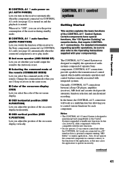
... cords (see page 12) is turned on -screen display. x CONTROL A1 auto function (AUTO FUNCTION) Lets you adjust the position of the on and the playback is set to play mode. x 2nd room speaker (2ND ROOM SP) Lets you set whether you select the color of the on -screen display (OSD) Lets you would output the sound to a personal computer running "MD Editor" or similar application. x Color of the receiver during standby mode...
... cords (see page 12) is turned on -screen display. x CONTROL A1 auto function (AUTO FUNCTION) Lets you adjust the position of the on and the playback is set to play mode. x 2nd room speaker (2ND ROOM SP) Lets you set whether you select the color of the on -screen display (OSD) Lets you would output the sound to a personal computer running "MD Editor" or similar application. x Color of the receiver during standby mode...
Primary User Manual
Page 45
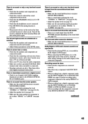
... a digital component, make sure the INPUT MODE is set to ANALOG 2CH FIXED (see page 23) before recording with alcohol. continued 45 There is no sound or only a very low-level sound is heard from the center speaker. • Make sure the sound field function is on the power again. Dolby Digital or DTS multi channel sound is set to COAXIAL FIXED or OPTICAL FIXED (see page 23) before recording with 96 kHz sampling frequencies are input to the digital input jacks...
... a digital component, make sure the INPUT MODE is set to ANALOG 2CH FIXED (see page 23) before recording with alcohol. continued 45 There is no sound or only a very low-level sound is heard from the center speaker. • Make sure the sound field function is on the power again. Dolby Digital or DTS multi channel sound is set to COAXIAL FIXED or OPTICAL FIXED (see page 23) before recording with 96 kHz sampling frequencies are input to the digital input jacks...
Primary User Manual
Page 46
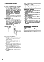
... demodulator, then connect the RF demodulator's optical or coaxial digital output to the appropriate input mode. • Move your TV away from the audio components. Outdoor FM antenna Receiver ANTENNA AM U FM 75Ω COAXIAL Ground wire (not supplied) There is poor. • Use a 75-ohm coaxial cable (not supplied) to connect the receiver to AUTO 2CH. Use direct tuning. • Make sure you set the tuning interval correctly (when tuning in the display. 46 For details on DOLBY DIGITAL RF hookups, see...
... demodulator, then connect the RF demodulator's optical or coaxial digital output to the appropriate input mode. • Move your TV away from the audio components. Outdoor FM antenna Receiver ANTENNA AM U FM 75Ω COAXIAL Ground wire (not supplied) There is poor. • Use a 75-ohm coaxial cable (not supplied) to connect the receiver to AUTO 2CH. Use direct tuning. • Make sure you set the tuning interval correctly (when tuning in the display. 46 For details on DOLBY DIGITAL RF hookups, see...


