Primary User Manual
Page 1
4-235-988-13(1) FM Stereo FM-AM Receiver Operating Instructions Owner's Record The model and serial numbers are located on the rear panel. Model No. Refer to them whenever you call upon your Sony dealer regarding this product. Record the serial number in the space provided below. Serial No. STR-DE1075 © 2001 Sony Corporation
4-235-988-13(1) FM Stereo FM-AM Receiver Operating Instructions Owner's Record The model and serial numbers are located on the rear panel. Model No. Refer to them whenever you call upon your Sony dealer regarding this product. Record the serial number in the space provided below. Serial No. STR-DE1075 © 2001 Sony Corporation
Primary User Manual
Page 2
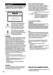
...of sufficient magnitude to constitute a risk of electric shock to Part 15 of the FCC Rules. This symbol is a U.S. Reorient or relocate the receiving antenna. - Connect the equipment into an outlet on a circuit different from Dolby Laboratories. registered mark. If this manual could void your remote,... trademarks of the NEC that any changes or modification not expressly approved in this model. As an ENERGY STAR® partner, Sony Corporation has determined that this product meets the ENERGY STAR® guidelines for this manual describe the controls on the remote is ...
...of sufficient magnitude to constitute a risk of electric shock to Part 15 of the FCC Rules. This symbol is a U.S. Reorient or relocate the receiving antenna. - Connect the equipment into an outlet on a circuit different from Dolby Laboratories. registered mark. If this manual could void your remote,... trademarks of the NEC that any changes or modification not expressly approved in this model. As an ENERGY STAR® partner, Sony Corporation has determined that this product meets the ENERGY STAR® guidelines for this manual describe the controls on the remote is ...

Primary User Manual
Page 3
... 25 Changing the display 25 Enjoying Surround Sound Selecting a sound field 26 Understanding the multi channel surround displays 30 Customizing sound fields 31 Receiving Broadcasts Direct tuning 36 Automatic tuning 36 Preset tuning 37 Other Operations Naming preset stations and program sources 38 Recording 38 Using the Sleep... press POWER KEY while this message appears in the display twice: "Now Demonstration Mode!! To cancel the demonstration Press ?/1 to turn the receiver on page 16. 3 The next time you !" Note Running the demonstration will be cleared, see "Clearing the...
... 25 Changing the display 25 Enjoying Surround Sound Selecting a sound field 26 Understanding the multi channel surround displays 30 Customizing sound fields 31 Receiving Broadcasts Direct tuning 36 Automatic tuning 36 Preset tuning 37 Other Operations Naming preset stations and program sources 38 Recording 38 Using the Sleep... press POWER KEY while this message appears in the display twice: "Now Demonstration Mode!! To cancel the demonstration Press ?/1 to turn the receiver on page 16. 3 The next time you !" Note Running the demonstration will be cleared, see "Clearing the...
Primary User Manual
Page 6
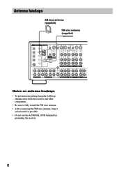
Antenna hookups AM loop antenna (supplied) FM wire antenna (supplied) DIGITAL ANTENNA CTRL S IN CTRL S STATUS IN CTRL S OUT CTRL...IN VIDEO OUT VIDEO IN VIDEO S-VIDEO S-VIDEO OUT IN VIDEO VIDEO MD/DAT OPTICAL IN MD/DAT OPTICAL OUT U FM CONTROL 75Ω A1 MONITOR COAXIAL AUDIO IN L AUDIO IN AUDIO OUT AUDIO IN AUDIO OUT AUDIO IN L DVD...To prevent noise pickup, keep the AM loop antenna away from the receiver and other components. • Be sure to fully extend the FM wire antenna. • After connecting the FM wire antenna, keep it as horizontal as possible. • Do not...
Antenna hookups AM loop antenna (supplied) FM wire antenna (supplied) DIGITAL ANTENNA CTRL S IN CTRL S STATUS IN CTRL S OUT CTRL...IN VIDEO OUT VIDEO IN VIDEO S-VIDEO S-VIDEO OUT IN VIDEO VIDEO MD/DAT OPTICAL IN MD/DAT OPTICAL OUT U FM CONTROL 75Ω A1 MONITOR COAXIAL AUDIO IN L AUDIO IN AUDIO OUT AUDIO IN AUDIO OUT AUDIO IN L DVD...To prevent noise pickup, keep the AM loop antenna away from the receiver and other components. • Be sure to fully extend the FM wire antenna. • After connecting the FM wire antenna, keep it as horizontal as possible. • Do not...
Primary User Manual
Page 8
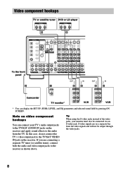
... VIDEO S-VIDEO IN VIDEO S-VIDEO IN VIDEO OUT VIDEO IN VIDEO S-VIDEO S-VIDEO OUT IN VIDEO VIDEO MD/DAT OPTICAL IN MD/DAT OPTICAL OUT U FM CONTROL 75Ω A1 MONITOR COAXIAL AUDIO IN L AUDIO IN AUDIO OUT AUDIO IN AUDIO OUT AUDIO IN L DVD/LD COAXIAL IN R TV/SAT DVD... jacks, your TV's audio output jacks to the audio from the video signals and will not be connected via an S-video jack. Note on the receiver and apply sound effects to the TV/SAT AUDIO IN jacks on video component hookups You can display the SET UP, SURR, LEVEL, and EQ...
... VIDEO S-VIDEO IN VIDEO S-VIDEO IN VIDEO OUT VIDEO IN VIDEO S-VIDEO S-VIDEO OUT IN VIDEO VIDEO MD/DAT OPTICAL IN MD/DAT OPTICAL OUT U FM CONTROL 75Ω A1 MONITOR COAXIAL AUDIO IN L AUDIO IN AUDIO OUT AUDIO IN AUDIO OUT AUDIO IN L DVD/LD COAXIAL IN R TV/SAT DVD... jacks, your TV's audio output jacks to the audio from the video signals and will not be connected via an S-video jack. Note on the receiver and apply sound effects to the TV/SAT AUDIO IN jacks on video component hookups You can display the SET UP, SURR, LEVEL, and EQ...
Primary User Manual
Page 9
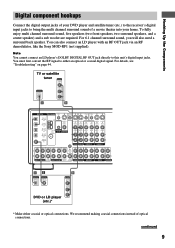
... Connect the digital output jacks of your DVD player and satellite tuner (etc.) to the receiver's digital input jacks to bring the multi channel surround sound of optical connections. You must .... You can also connect an LD player with an RF OUT jack via an RF demodulator, like the Sony MOD-RF1 (not supplied). TV or satellite tuner OUTPUT VIDEO OUT OUTPUT DIGITAL OPTICAL AUDIO OUT L R ... S-VIDEO OUT IN VIDEO VIDEO MD/DAT OPTICAL IN MD/DAT OPTICAL OUT DVD/LD COAXIAL IN U FM CONTROL 75Ω A1 MONITOR COAXIAL AUDIO IN L AUDIO IN AUDIO OUT AUDIO IN AUDIO OUT AUDIO ...
... Connect the digital output jacks of your DVD player and satellite tuner (etc.) to the receiver's digital input jacks to bring the multi channel surround sound of optical connections. You must .... You can also connect an LD player with an RF OUT jack via an RF demodulator, like the Sony MOD-RF1 (not supplied). TV or satellite tuner OUTPUT VIDEO OUT OUTPUT DIGITAL OPTICAL AUDIO OUT L R ... S-VIDEO OUT IN VIDEO VIDEO MD/DAT OPTICAL IN MD/DAT OPTICAL OUT DVD/LD COAXIAL IN U FM CONTROL 75Ω A1 MONITOR COAXIAL AUDIO IN L AUDIO IN AUDIO OUT AUDIO IN AUDIO OUT AUDIO ...
Primary User Manual
Page 10
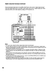
... S-VIDEO IN IN VIDEO VIDEO OUT VIDEO IN VIDEO S-VIDEO S-VIDEO OUT IN VIDEO VIDEO MD/DAT OPTICAL IN MD/DAT OPTICAL OUT U FM CONTROL 75Ω A1 MONITOR COAXIAL AUDIO IN L AUDIO IN AUDIO OUT AUDIO IN AUDIO OUT AUDIO IN L DVD/LD COAXIAL IN R TV...are compatible with 48 kHz, 44.1 kHz and 32 kHz sampling frequencies. • It is compatible with 96 kHz sampling frequencies, connect to the receiver's digital output jack. To record digital signals, make a digital recording from this jack may result in intermittent sound. 10 Digital component hookups (continued...
... S-VIDEO IN IN VIDEO VIDEO OUT VIDEO IN VIDEO S-VIDEO S-VIDEO OUT IN VIDEO VIDEO MD/DAT OPTICAL IN MD/DAT OPTICAL OUT U FM CONTROL 75Ω A1 MONITOR COAXIAL AUDIO IN L AUDIO IN AUDIO OUT AUDIO IN AUDIO OUT AUDIO IN L DVD/LD COAXIAL IN R TV...are compatible with 48 kHz, 44.1 kHz and 32 kHz sampling frequencies. • It is compatible with 96 kHz sampling frequencies, connect to the receiver's digital output jack. To record digital signals, make a digital recording from this jack may result in intermittent sound. 10 Digital component hookups (continued...
Primary User Manual
Page 11
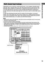
... the connections described below, adjust the level of the DVD player's multi channel decoder. Hooking Up the Components Multi channel input hookups Although this receiver incorporates a multi channel decoder, it is also equipped with multi channel output jacks, you can be used to connect an external multi channel decoder...S-VIDEO IN VIDEO S-VIDEO IN VIDEO OUT VIDEO IN VIDEO S-VIDEO S-VIDEO OUT IN VIDEO VIDEO MD/DAT OPTICAL IN MD/DAT OPTICAL OUT U FM CONTROL 75Ω A1 MONITOR COAXIAL AUDIO IN L AUDIO IN AUDIO OUT AUDIO IN AUDIO OUT AUDIO IN L DVD/LD COAXIAL IN R TV/...
... the connections described below, adjust the level of the DVD player's multi channel decoder. Hooking Up the Components Multi channel input hookups Although this receiver incorporates a multi channel decoder, it is also equipped with multi channel output jacks, you can be used to connect an external multi channel decoder...S-VIDEO IN VIDEO S-VIDEO IN VIDEO OUT VIDEO IN VIDEO S-VIDEO S-VIDEO OUT IN VIDEO VIDEO MD/DAT OPTICAL IN MD/DAT OPTICAL OUT U FM CONTROL 75Ω A1 MONITOR COAXIAL AUDIO IN L AUDIO IN AUDIO OUT AUDIO IN AUDIO OUT AUDIO IN L DVD/LD COAXIAL IN R TV/...
Primary User Manual
Page 12
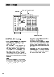
... be sure to set the command mode to "CD 2" and connect the changer to the CONTROL A1 jack on the receiver. Other hookups CTRL S (STATUS) IN/OUT CONTROL A1 H H DIGITAL ANTENNA CTRL S IN CTRL S STATUS IN...VIDEO IN VIDEO S-VIDEO S-VIDEO OUT IN VIDEO VIDEO MD/DAT OPTICAL IN MD/DAT OPTICAL OUT U FM CONTROL 75Ω A1 MONITOR COAXIAL AUDIO IN L AUDIO IN AUDIO OUT AUDIO IN AUDIO OUT AUDIO...player, SACD player, tape deck, or MD deck to the VIDEO 2 jacks on the receiver. 12 Note If you have a Sony CD changer with VIDEO OUT jacks, set the command mode to "CD 1" and connect...
... be sure to set the command mode to "CD 2" and connect the changer to the CONTROL A1 jack on the receiver. Other hookups CTRL S (STATUS) IN/OUT CONTROL A1 H H DIGITAL ANTENNA CTRL S IN CTRL S STATUS IN...VIDEO IN VIDEO S-VIDEO S-VIDEO OUT IN VIDEO VIDEO MD/DAT OPTICAL IN MD/DAT OPTICAL OUT U FM CONTROL 75Ω A1 MONITOR COAXIAL AUDIO IN L AUDIO IN AUDIO OUT AUDIO IN AUDIO OUT AUDIO...player, SACD player, tape deck, or MD deck to the VIDEO 2 jacks on the receiver. 12 Note If you have a Sony CD changer with VIDEO OUT jacks, set the command mode to "CD 1" and connect...
Primary User Manual
Page 13
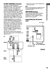
... TV input mode will change the input mode of the receiver to TV whenever you operate your TV for details. SURROUND BACK + ND BACK L ROOM - Hooking Up the Components S-LINK CONTROL S hookup If you have a S-LINK CONTROL Scompatible Sony TV, satellite tuner, monitor, DVD player or VCR, ...use the 2ND ROOM OUT jacks to output the audio signals of the selected component to a stereo amplifier located in another room (see page 25).
... TV input mode will change the input mode of the receiver to TV whenever you operate your TV for details. SURROUND BACK + ND BACK L ROOM - Hooking Up the Components S-LINK CONTROL S hookup If you have a S-LINK CONTROL Scompatible Sony TV, satellite tuner, monitor, DVD player or VCR, ...use the 2ND ROOM OUT jacks to output the audio signals of the selected component to a stereo amplifier located in another room (see page 25).
Primary User Manual
Page 14
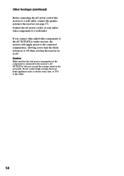
... Do not connect high-wattage electrical home appliances such as electric irons, fans, or TVs to the receiver's AC OUTLET(s) does not exceed the wattage stated on or off when you turn the receiver on the rear panel. Other hookups (continued) Before connecting the AC power cord of this outlet. 14... Connect the AC power cord(s) of your audio/ video components to the receiver (see page 17). If you connect other audio/video components to the AC OUTLET(s) on the receiver, the receiver will supply power to the connected component(s), allowing you to turn the whole system on or ...
... Do not connect high-wattage electrical home appliances such as electric irons, fans, or TVs to the receiver's AC OUTLET(s) does not exceed the wattage stated on or off when you turn the receiver on the rear panel. Other hookups (continued) Before connecting the AC power cord of this outlet. 14... Connect the AC power cord(s) of your audio/ video components to the receiver (see page 17). If you connect other audio/video components to the AC OUTLET(s) on the receiver, the receiver will supply power to the connected component(s), allowing you to turn the whole system on or ...
Primary User Manual
Page 16
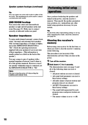
...have hooked up while outputting the sound), check the connection (see page 3) and all of the two jacks. Clearing the receiver's memory Before using your receiver for 5 seconds. Check the operating instructions supplied with your system. The remaining jack can be used to "4Ω". However... multi channel surround, connect front, center, surround, and surround back speakers with a nominal impedance between 4 and 8 ohms to clear the receiver's memory, do the following items are reset or cleared: • All preset stations are reset or cleared. • All sound field parameters...
...have hooked up while outputting the sound), check the connection (see page 3) and all of the two jacks. Clearing the receiver's memory Before using your receiver for 5 seconds. Check the operating instructions supplied with your system. The remaining jack can be used to "4Ω". However... multi channel surround, connect front, center, surround, and surround back speakers with a nominal impedance between 4 and 8 ohms to clear the receiver's memory, do the following items are reset or cleared: • All preset stations are reset or cleared. • All sound field parameters...

Primary User Manual
Page 17
... falls, make sure that it from the listening position (A). Hooking Up and Setting Up the Speaker System Performing initial setup operations Before using your receiver for other settings. The setting is entered automatically. 4 Repeat steps 2 and 3 until you to place the center speaker up to 5 feet... 17-22 for speaker settings and pages 40, 41 for the first time, adjust SET UP parameters so that follow. However, the receiver lets you have set all speakers should be placed from the listening position (A). When placing surround speakers to the side, depending on page...
... falls, make sure that it from the listening position (A). Hooking Up and Setting Up the Speaker System Performing initial setup operations Before using your receiver for other settings. The setting is entered automatically. 4 Repeat steps 2 and 3 until you to place the center speaker up to 5 feet... 17-22 for speaker settings and pages 40, 41 for the first time, adjust SET UP parameters so that follow. However, the receiver lets you have set all speakers should be placed from the listening position (A). When placing surround speakers to the side, depending on page...
Primary User Manual
Page 20
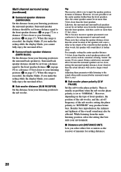
Tip The receiver allows you cannot fully enjoy the surround effect. And they can not be set farther away from your environment. There is exceeded, the display blinks. ... 15 feet closer to input the speaker position in terms of distance. x Distance unit (DISTANCE UNIT) Lets you select either feet or meters as the receiver of being "inside" the screen.
Tip The receiver allows you cannot fully enjoy the surround effect. And they can not be set farther away from your environment. There is exceeded, the display blinks. ... 15 feet closer to input the speaker position in terms of distance. x Distance unit (DISTANCE UNIT) Lets you select either feet or meters as the receiver of being "inside" the screen.
Primary User Manual
Page 22
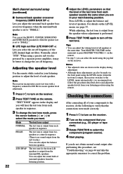
...measures to the LEVEL menu automatically), we recommend you follow the procedure described above and adjust the speaker levels from your components to the receiver, do the following to verify that you connected (e.g., CD player or tape deck). 3 Rotate FUNCTION to "SMALL". Notes • The... you can also adjust the balance between speakers. While adjusting, the test tone is output from the speaker whose adjustment is output, the receiver switches to correct the problem. Multi channel surround setup (continued) x Surround back speaker crossover frequency (SURR BACK SP >) Lets you adjust...
...measures to the LEVEL menu automatically), we recommend you follow the procedure described above and adjust the speaker levels from your components to the receiver, do the following to verify that you connected (e.g., CD player or tape deck). 3 Rotate FUNCTION to "SMALL". Notes • The... you can also adjust the balance between speakers. While adjusting, the test tone is output from the speaker whose adjustment is output, the receiver switches to correct the problem. Multi channel surround setup (continued) x Surround back speaker crossover frequency (SURR BACK SP >) Lets you adjust...
Primary User Manual
Page 25
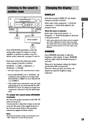
...Index name of the current function is output. • Even if 2ND ROOM is set to a stereo amplifier or speakers in another room Changing the display DISPLAY Basic Operations •• SPEAKERS 2ND ROOM OUT AUDIO IN... Stereo amplifier SPEAKERS Press 2ND ROOM repeatedly to select the analog audio signals for output to "SOURCE", the ...The audio signals of the preset station* t Frequency t Sound field applied to the analog input jacks are turned off the receiver. 25
...Index name of the current function is output. • Even if 2ND ROOM is set to a stereo amplifier or speakers in another room Changing the display DISPLAY Basic Operations •• SPEAKERS 2ND ROOM OUT AUDIO IN... Stereo amplifier SPEAKERS Press 2ND ROOM repeatedly to select the analog audio signals for output to "SOURCE", the ...The audio signals of the preset station* t Frequency t Sound field applied to the analog input jacks are turned off the receiver. 25
Primary User Manual
Page 26
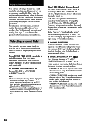
... programs are labeled with the logo. • When sound signals with Dolby Pro Logic to reproduce the sound characteristic of the receiver's preprogrammed sound fields. DCS uses the DSP (Digital Signal Processor) technology to create surround effects. Enjoying Surround Sound You can ...signals are selected, "Digital Cinema Sound" indicator in the display lights up -todate facilities in stereo automatically, and the sound field is decoded with a sampling frequency of Sony Pictures Entertainment's mixing studio which is played back according to select the sound field you want ...
... programs are labeled with the logo. • When sound signals with Dolby Pro Logic to reproduce the sound characteristic of the receiver's preprogrammed sound fields. DCS uses the DSP (Digital Signal Processor) technology to create surround effects. Enjoying Surround Sound You can ...signals are selected, "Digital Cinema Sound" indicator in the display lights up -todate facilities in stereo automatically, and the sound field is decoded with a sampling frequency of Sony Pictures Entertainment's mixing studio which is played back according to select the sound field you want ...
Primary User Manual
Page 30
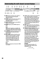
...when MPEG signals are input. or "NORMAL SURROUND" is decoding signals recorded in the Dolby Digital format. 6 PRO LOGIC: Lights up when the receiver applies Pro Logic processing to 2 channel signals in all parts of the LFE channel signal is selected. 4 MPEG: Lights up when sub woofer selection...(the surround back components obtained by 6.1 matrix decoding)) Example: Recording format (Front /Rear): 3/2 Output channel: Rear speakers absent Sound Field: A.F.D. SW L CR STEREO MONO MEMORY SL SR RDS SSB 2ND ROOM SP. Since the LFE signal is not recorded in order to show how the...
...when MPEG signals are input. or "NORMAL SURROUND" is decoding signals recorded in the Dolby Digital format. 6 PRO LOGIC: Lights up when the receiver applies Pro Logic processing to 2 channel signals in all parts of the LFE channel signal is selected. 4 MPEG: Lights up when sub woofer selection...(the surround back components obtained by 6.1 matrix decoding)) Example: Recording format (Front /Rear): 3/2 Output channel: Rear speakers absent Sound Field: A.F.D. SW L CR STEREO MONO MEMORY SL SR RDS SSB 2ND ROOM SP. Since the LFE signal is not recorded in order to show how the...
Primary User Manual
Page 31
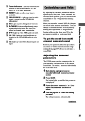
... to OFF. Customizing sound fields By adjusting the surround parameters and the equalization of the current sound field. qd EQ: Lights up when using the receiver to the parameters. You can customize the sound fields to select the setting you customize various aspects of the front, center, surround, and surround back...
... to OFF. Customizing sound fields By adjusting the surround parameters and the equalization of the current sound field. qd EQ: Lights up when using the receiver to the parameters. You can customize the sound fields to select the setting you customize various aspects of the front, center, surround, and surround back...
Primary User Manual
Page 32
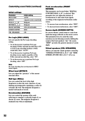
... DEPTH VIR. Reverberation (REVERB) Lets you control the spacing of the Dolby surround encoded flag, select "ON". • To set the receiver not to alter the sonic character of screen depth. Screen depth (SCREEN DEPTH) In a movie theater, sound seems to the original reverberations... used when "DIGITAL CONCERT HALL A, B" is ON or if Pro Logic decoding produces a better sound field, select "AUTO". • To set the receiver to simulate a sonically longer (L) or shorter (S) room. SPEAKERS) Allows you create the same sensation in the source. • To increase front reverberations, ...
... DEPTH VIR. Reverberation (REVERB) Lets you control the spacing of the Dolby surround encoded flag, select "ON". • To set the receiver not to alter the sonic character of screen depth. Screen depth (SCREEN DEPTH) In a movie theater, sound seems to the original reverberations... used when "DIGITAL CONCERT HALL A, B" is ON or if Pro Logic decoding produces a better sound field, select "AUTO". • To set the receiver to simulate a sonically longer (L) or shorter (S) room. SPEAKERS) Allows you create the same sensation in the source. • To increase front reverberations, ...


