
Limited Warranty (U.S. Only)
Page 1
...consequential damages, or allow limitations on how long an implied warranty lasts does not apply to any Sony authorized service facility. This warranty does not cover customer instruction, installation, set up adjustments or signal reception problems. This warranty does not cover cosmetic damage ...exclusions may have other than a facility authorized by Sony to service the Product. 4-557-173-02 General Stereo/Hifi Components/Tape Decks ® CD Players/Mini Disc Players/Audio Systems Hifi Audio LIMITED WARRANTY Sony Electronics Inc. ("Sony") warrants this Product is valid only in the...
...consequential damages, or allow limitations on how long an implied warranty lasts does not apply to any Sony authorized service facility. This warranty does not cover customer instruction, installation, set up adjustments or signal reception problems. This warranty does not cover cosmetic damage ...exclusions may have other than a facility authorized by Sony to service the Product. 4-557-173-02 General Stereo/Hifi Components/Tape Decks ® CD Players/Mini Disc Players/Audio Systems Hifi Audio LIMITED WARRANTY Sony Electronics Inc. ("Sony") warrants this Product is valid only in the...
Operating Instructions
Page 1
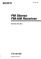
4-241-670-11(3) FM Stereo FM-AM Receiver Operating Instructions STR-DB1080 © 2002 Sony Corporation
4-241-670-11(3) FM Stereo FM-AM Receiver Operating Instructions STR-DB1080 © 2002 Sony Corporation
Operating Instructions
Page 3
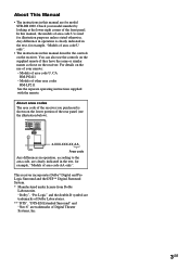
...area codes RM-LP211 See the separate operating instructions supplied with the remote. This receiver incorporates Dolby* Digital and Pro Logic Surround and the DTS** Digital Surround System. * Manufactured under license from Dolby Laboratories. In this manual are for model STR-DB1080. "Dolby", "Pro Logic" and the ...of area code AA only". About area codes The area code of the receiver you purchased is used for illustration purposes unless stated otherwise. Check your remote: - About This Manual • The instructions in the text, for example, "Models of the front panel. For ...
...area codes RM-LP211 See the separate operating instructions supplied with the remote. This receiver incorporates Dolby* Digital and Pro Logic Surround and the DTS** Digital Surround System. * Manufactured under license from Dolby Laboratories. In this manual are for model STR-DB1080. "Dolby", "Pro Logic" and the ...of area code AA only". About area codes The area code of the receiver you purchased is used for illustration purposes unless stated otherwise. Check your remote: - About This Manual • The instructions in the text, for example, "Models of the front panel. For ...
Operating Instructions
Page 12
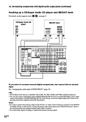
...DAT OPTICAL OUT DVD/LD COAXIAL IN S-VIDEO AM OUT VIDEO S-VIDEO IN VIDEO S-VIDEO IN VIDEO OUT VIDEO IN VIDEO U FM 75Ω COAXIAL MONITOR CONTROL AUDIO A1 IN L R AUDIO IN AUDIO OUT AUDIO IN TV/SAT DVD/LD VIDEO 2 ... components, but cannot find an unused input See "Assigning the audio input (AUDIO SPLIT)" (page 41). Refer to the operating instructions supplied with the RF demodulator. R SUB SURROUND SUB MULTI CH IN 2 WOOFER MULTI CH IN 1 BACK WOOFER PHONO CD/SACD... RF demodulator (You cannot connect an LD player's DOLBY DIGITAL RF OUT jack directly to this receiver.
...DAT OPTICAL OUT DVD/LD COAXIAL IN S-VIDEO AM OUT VIDEO S-VIDEO IN VIDEO S-VIDEO IN VIDEO OUT VIDEO IN VIDEO U FM 75Ω COAXIAL MONITOR CONTROL AUDIO A1 IN L R AUDIO IN AUDIO OUT AUDIO IN TV/SAT DVD/LD VIDEO 2 ... components, but cannot find an unused input See "Assigning the audio input (AUDIO SPLIT)" (page 41). Refer to the operating instructions supplied with the RF demodulator. R SUB SURROUND SUB MULTI CH IN 2 WOOFER MULTI CH IN 1 BACK WOOFER PHONO CD/SACD... RF demodulator (You cannot connect an LD player's DOLBY DIGITAL RF OUT jack directly to this receiver.

Operating Instructions
Page 18
... surround, connect speakers with a nominal impedance between 4 and 8 ohms to any or all of the speaker terminals. Refer to the operating instructions supplied with your speakers to the receiver. This receiver alows you connect even one additional surround back speaker (6.1 channel). (See "Selecting the surround back decoding mode" on the back of 8 ohms...
... surround, connect speakers with a nominal impedance between 4 and 8 ohms to any or all of the speaker terminals. Refer to the operating instructions supplied with your speakers to the receiver. This receiver alows you connect even one additional surround back speaker (6.1 channel). (See "Selecting the surround back decoding mode" on the back of 8 ohms...
Operating Instructions
Page 23
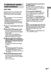
... in this setting, it takes a few seconds to "FIX" (page 44). For details on the receiver. • You can output the test tone or sound source from a specific speaker Set "TEST TONE" in the CUSTOMIZE menu to the operating instructions supplied with the remote. on the remote or turn on the... receiver for the operation. To output the test tone only from two adjacent speakers to "AUTO OFF" (page 47). 23GB...
... in this setting, it takes a few seconds to "FIX" (page 44). For details on the receiver. • You can output the test tone or sound source from a specific speaker Set "TEST TONE" in the CUSTOMIZE menu to the operating instructions supplied with the remote. on the remote or turn on the... receiver for the operation. To output the test tone only from two adjacent speakers to "AUTO OFF" (page 47). 23GB...
Operating Instructions
Page 26
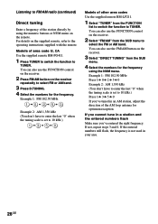
... codes Use the supplied remote RM-LP211. 1 Select "TUNER" from the SUB menu to select the FM or AM band. You can also use the FM/AM button on the supplied remote, refer to the operating instructions supplied with the remote. Models of area code U, CA Use the supplied remote RM-PG411. 1 Press..., the frequency is set to 10 kHz.) Press 1 b 3 b 5 b 0 If you 've entered the right frequency. You can also use the FUNCTION control on the receiver. 2 Press FM/AM button on the remote. If you cannot tune in a station and the entered numbers flash Make sure you 've tuned in your area. 26GB...
... codes Use the supplied remote RM-LP211. 1 Select "TUNER" from the SUB menu to select the FM or AM band. You can also use the FM/AM button on the supplied remote, refer to the operating instructions supplied with the remote. Models of area code U, CA Use the supplied remote RM-PG411. 1 Press..., the frequency is set to 10 kHz.) Press 1 b 3 b 5 b 0 If you 've entered the right frequency. You can also use the FUNCTION control on the receiver. 2 Press FM/AM button on the remote. If you cannot tune in a station and the entered numbers flash Make sure you 've tuned in your area. 26GB...

Operating Instructions
Page 57
...the remote. Each time you want to the FRONT SPEAKERS A terminals. Select SLEEP from the RECEIVER menu repeatedly while the power is on. The speakers connected to turn off , touch or press... SLEEP button on . The sound field is automatically set the IMPEDANCE SELECTOR to the operating instructions supplied with a nominal impedance of area code U, CA, CEL, CEK, SP, KR ... lights up in the display. The remaining time appears in the display. The speakers connected to 2CH STEREO. In this case, set to both sets of area code U, CA Use the supplied remote RM-PG411...
...the remote. Each time you want to the FRONT SPEAKERS A terminals. Select SLEEP from the RECEIVER menu repeatedly while the power is on. The speakers connected to turn off , touch or press... SLEEP button on . The sound field is automatically set the IMPEDANCE SELECTOR to the operating instructions supplied with a nominal impedance of area code U, CA, CEL, CEK, SP, KR ... lights up in the display. The remaining time appears in the display. The speakers connected to 2CH STEREO. In this case, set to both sets of area code U, CA Use the supplied remote RM-PG411...
Operating Instructions
Page 58
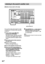
...DAT OPTICAL IN MD/DAT OPTICAL OUT DVD/LD COAXIAL IN S-VIDEO AM OUT VIDEO S-VIDEO IN VIDEO S-VIDEO IN VIDEO OUT VIDEO IN VIDEO U FM 75Ω COAXIAL MONITOR CONTROL AUDIO A1 IN L R AUDIO IN AUDIO OUT AUDIO IN TV/SAT DVD/LD VIDEO 2 FRONT SURROUND CENTER FRONT SURROUND... the 2nd room. The remote switches to the 2nd room mode. For details on the supplied remote, refer to the operating instructions supplied with the remote. 2 Turn on the receiver (this receiver) in the main room. 3 Press ?/1 on the connection, see page 59. 1 On the remote, press 2ND while pressing down ...
...DAT OPTICAL IN MD/DAT OPTICAL OUT DVD/LD COAXIAL IN S-VIDEO AM OUT VIDEO S-VIDEO IN VIDEO S-VIDEO IN VIDEO OUT VIDEO IN VIDEO U FM 75Ω COAXIAL MONITOR CONTROL AUDIO A1 IN L R AUDIO IN AUDIO OUT AUDIO IN TV/SAT DVD/LD VIDEO 2 FRONT SURROUND CENTER FRONT SURROUND... the 2nd room. The remote switches to the 2nd room mode. For details on the supplied remote, refer to the operating instructions supplied with the remote. 2 Turn on the receiver (this receiver) in the main room. 3 Press ?/1 on the connection, see page 59. 1 On the remote, press 2ND while pressing down ...
Operating Instructions
Page 60
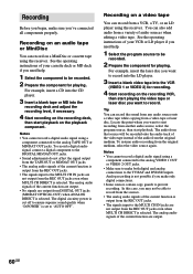
... • No signals are not output from DIGITAL OUT jacks (MD/DAT OPTICAL OUT) when ANALOG DIRECT is selected. See the operating instructions of your VCR or LD player if you want to start playback on the recording VCR, then start playback. The audio from that source... from a variety of the current function is selected. Notes • You cannot record a digital audio signal using the receiver. Notes • You cannot record a digital audio signal using the receiver. In this case, you may not be recorded. 2 Prepare the component for recording. 4 Start recording on the playback...
... • No signals are not output from DIGITAL OUT jacks (MD/DAT OPTICAL OUT) when ANALOG DIRECT is selected. See the operating instructions of your VCR or LD player if you want to start playback on the recording VCR, then start playback. The audio from that source... from a variety of the current function is selected. Notes • You cannot record a digital audio signal using the receiver. Notes • You cannot record a digital audio signal using the receiver. In this case, you may not be recorded. 2 Prepare the component for recording. 4 Start recording on the playback...

Operating Instructions
Page 61
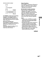
...be sure to also refer to operate incorrectly. In this may cause the application to the Operating Instructions supplied with integrated systems. Currently, CONTROL A1 connections between a Sony CD player, amplifier (receiver), MD deck and cassette deck provide automatic function selection and synchronized recording. R SUB SURROUND SUB ... MD/DAT OPTICAL OUT DVD/LD COAXIAL IN S-VIDEO AM OUT VIDEO S-VIDEO IN VIDEO S-VIDEO IN VIDEO OUT VIDEO IN VIDEO U FM 75Ω COAXIAL MONITOR CONTROL AUDIO A1 IN L R AUDIO IN AUDIO OUT AUDIO IN TV/SAT DVD/LD VIDEO 2 FRONT SURROUND...
...be sure to also refer to operate incorrectly. In this may cause the application to the Operating Instructions supplied with integrated systems. Currently, CONTROL A1 connections between a Sony CD player, amplifier (receiver), MD deck and cassette deck provide automatic function selection and synchronized recording. R SUB SURROUND SUB ... MD/DAT OPTICAL OUT DVD/LD COAXIAL IN S-VIDEO AM OUT VIDEO S-VIDEO IN VIDEO S-VIDEO IN VIDEO OUT VIDEO IN VIDEO U FM 75Ω COAXIAL MONITOR CONTROL AUDIO A1 IN L R AUDIO IN AUDIO OUT AUDIO IN TV/SAT DVD/LD VIDEO 2 FRONT SURROUND...

Operating Instructions
Page 62
...from the receiver to an MD deck that can be controlled may cause a malfunction. • If you have a Sony CD changer with VIDEO OUT jacks, set the command mode to "CD 1" and connect the changer to each type of IN and OUT jacks. Refer to the operating instructions supplied ...with CONTROL A1 , and can connect up to a computer, do not operate the receiver while using the "Sony MD Editor" software. Components with CONTROL A1 jacks are compatible with components with the respective...
...from the receiver to an MD deck that can be controlled may cause a malfunction. • If you have a Sony CD changer with VIDEO OUT jacks, set the command mode to "CD 1" and connect the changer to each type of IN and OUT jacks. Refer to the operating instructions supplied ...with CONTROL A1 , and can connect up to a computer, do not operate the receiver while using the "Sony MD Editor" software. Components with CONTROL A1 jacks are compatible with components with the respective...
Operating Instructions
Page 63
... feature. • This function only works when the components are connected to the amplifier (or receiver) inputs according to the operating instructions supplied with the receiver. • When recording, do not play button on one of the connected components. continued Other... In this case, refer to the correct input when you connect a CONTROL A1 compatible Sony amplifier (or receiver) to other Sony components using monaural miniplug cords, the function selector on the amplifier (or receiver) automatically switches to the operating instructions supplied with the component(s).
... feature. • This function only works when the components are connected to the amplifier (or receiver) inputs according to the operating instructions supplied with the receiver. • When recording, do not play button on one of the connected components. continued Other... In this case, refer to the correct input when you connect a CONTROL A1 compatible Sony amplifier (or receiver) to other Sony components using monaural miniplug cords, the function selector on the amplifier (or receiver) automatically switches to the operating instructions supplied with the component(s).
Operating Instructions
Page 64
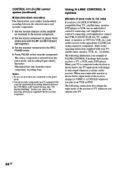
... code U, CA only) If you play your VCR or DVD. When you connect the receiver as shown below , input mode of the receiver to VIDEO 1 or DVD/LD whenever you have a S-LINK CONTROL Scompatible Sony TV, satellite tuner, monitor, DVD player or VCR, use an audio/video/ control S...to pause mode (make sure both the N and X indicators light together). 3 Set the recorder component to the operating instructions supplied with your TV. 64GB Refer to the operating instructions supplied with the recorder component. Notes • Do not set more than one component to connect the CTRL S (...
... code U, CA only) If you play your VCR or DVD. When you connect the receiver as shown below , input mode of the receiver to VIDEO 1 or DVD/LD whenever you have a S-LINK CONTROL Scompatible Sony TV, satellite tuner, monitor, DVD player or VCR, use an audio/video/ control S...to pause mode (make sure both the N and X indicators light together). 3 Set the recorder component to the operating instructions supplied with your TV. 64GB Refer to the operating instructions supplied with the recorder component. Notes • Do not set more than one component to connect the CTRL S (...

Operating Instructions
Page 65
.... *2 Control S cord (supplied). *3 Audio/video cord (not supplied). *4 Control S cord (not supplied). Note Refer to the operating instructions supplied with your TV. 65GB Other Operations TV S-LINK OUT IN VIDEO IN AUDIO OUT *1 Receiver *2 *1 MONITOR TV/SAT DVD/LD IN STATUS IN OUT S2 VIDEO S2 VIDEO S2 VIDEO OUT IN IN...
.... *2 Control S cord (supplied). *3 Audio/video cord (not supplied). *4 Control S cord (not supplied). Note Refer to the operating instructions supplied with your TV. 65GB Other Operations TV S-LINK OUT IN VIDEO IN AUDIO OUT *1 Receiver *2 *1 MONITOR TV/SAT DVD/LD IN STATUS IN OUT S2 VIDEO S2 VIDEO S2 VIDEO OUT IN IN...
Operating Instructions
Page 68
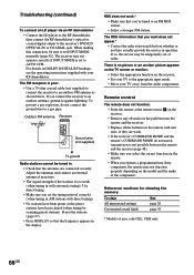
...sure to set to AUTO 2CH. If so, the service may not function properly depending on DOLBY DIGITAL RF hookups, see the operating instructions supplied with direct tuning). • No stations have been preset or the preset stations have been cleared (when tuning by scanning preset .... • Select a stronger FM station. The receiver may not operate correctly if INPUT MODE is not possible between the remote and the receiver (page 48). • Make sure you select the correct function on the remote. • When you operate a programmed non-Sony component, the remote may be ...
...sure to set to AUTO 2CH. If so, the service may not function properly depending on DOLBY DIGITAL RF hookups, see the operating instructions supplied with direct tuning). • No stations have been preset or the preset stations have been cleared (when tuning by scanning preset .... • Select a stronger FM station. The receiver may not operate correctly if INPUT MODE is not possible between the remote and the receiver (page 48). • Make sure you select the correct function on the remote. • When you operate a programmed non-Sony component, the remote may be ...


