
Limited Warranty (U.S. Only)
Page 1
...an accessory or part not available from the Product. 4-557-173-02 General Stereo/Hifi Components/Tape Decks ® CD Players/Mini Disc Players/Audio Systems Hifi Audio LIMITED WARRANTY Sony Electronics Inc. ("Sony") warrants this Product is within 90 days of the date of two (2) ... from state to you must pay for product information or operation, call : 1-800-488-SONY (7669) Printed in Japan After the Warranty Period, you . This warranty does not cover customer instruction, installation, set up adjustments or signal reception problems. This warranty does not cover cosmetic damage...
...an accessory or part not available from the Product. 4-557-173-02 General Stereo/Hifi Components/Tape Decks ® CD Players/Mini Disc Players/Audio Systems Hifi Audio LIMITED WARRANTY Sony Electronics Inc. ("Sony") warrants this Product is within 90 days of the date of two (2) ... from state to you must pay for product information or operation, call : 1-800-488-SONY (7669) Printed in Japan After the Warranty Period, you . This warranty does not cover customer instruction, installation, set up adjustments or signal reception problems. This warranty does not cover cosmetic damage...
Service Manual
Page 3
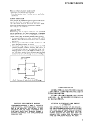
... leakage tester, such as described below. Measuring the voltage drop across a resistor by heat. STR-DB870/DB1070 SAFETY-RELATED COMPONENT WARNING!! Leakage current can be dam- ATTENTION AU COMPOSANT AYANT RAPPORT À...; LA SÉCURITÉ! Check leakage as the Simpson 229 or RCA WT-540A. Follow the manufacturers' instructions...NE REMPLACER CES COMPOSANTS QUE PAR DES PIÈCES SONY DONT LES NUMÉROS SONT DONNÉS DANS CE MANUEL OU DANS LES SUPPLÉMENTS...
... leakage tester, such as described below. Measuring the voltage drop across a resistor by heat. STR-DB870/DB1070 SAFETY-RELATED COMPONENT WARNING!! Leakage current can be dam- ATTENTION AU COMPOSANT AYANT RAPPORT À...; LA SÉCURITÉ! Check leakage as the Simpson 229 or RCA WT-540A. Follow the manufacturers' instructions...NE REMPLACER CES COMPOSANTS QUE PAR DES PIÈCES SONY DONT LES NUMÉROS SONT DONNÉS DANS CE MANUEL OU DANS LES SUPPLÉMENTS...
Service Manual
Page 6
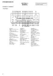
... only) eg (27) SURR ea (33) TEST TONE ej (24) TUNING +/- STR-DB870/DB1070 LOCATION OF CONTROLS - Front Panel - SECTION 2 GENERAL 1 2 3 45678 9 0 qa qsqdqf qg qh qj qk ql This section is extracted from instruction manual. qh (28, 37) MULTI/2CH A. eh (39) VIDEO 3 INPUT jacks ra ?/1 (power) 1 (18, 23, 24, 37, 38... (27) Digital Cinema Sound indicator 5 (28) Display qj (32) DISPLAY 3 (27, 41) DOOR OPEN wg ENTER wh (43) EQ e; (36) EQUALIZER ef (36) FM/AM 6 (38, 39) FM MODE r; (39) FUNCTION wd (24, 25, 38, 39, 40, 43) INPUT MODE wf (26) IR receptor 2 Jog dial wk (19, 33, 35, 36, 43...
... only) eg (27) SURR ea (33) TEST TONE ej (24) TUNING +/- STR-DB870/DB1070 LOCATION OF CONTROLS - Front Panel - SECTION 2 GENERAL 1 2 3 45678 9 0 qa qsqdqf qg qh qj qk ql This section is extracted from instruction manual. qh (28, 37) MULTI/2CH A. eh (39) VIDEO 3 INPUT jacks ra ?/1 (power) 1 (18, 23, 24, 37, 38... (27) Digital Cinema Sound indicator 5 (28) Display qj (32) DISPLAY 3 (27, 41) DOOR OPEN wg ENTER wh (43) EQ e; (36) EQUALIZER ef (36) FM/AM 6 (38, 39) FM MODE r; (39) FUNCTION wd (24, 25, 38, 39, 40, 43) INPUT MODE wf (26) IR receptor 2 Jog dial wk (19, 33, 35, 36, 43...
Operating Instructions (primary manual)
Page 1
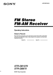
Model No. STR-DB1070 STR-DB870 © 2001 Sony Corporation Record the serial number in the space provided below. Refer to them whenever you call upon your Sony dealer regarding this product. 4-235-985-14(1) FM Stereo FM-AM Receiver Operating Instructions Owner's Record The model and serial numbers are located on the rear panel. Serial No.
Model No. STR-DB1070 STR-DB870 © 2001 Sony Corporation Record the serial number in the space provided below. Refer to them whenever you call upon your Sony dealer regarding this product. 4-235-985-14(1) FM Stereo FM-AM Receiver Operating Instructions Owner's Record The model and serial numbers are located on the rear panel. Serial No.
Operating Instructions (primary manual)
Page 2
...STAR® is encouraged to try to persons. As an ENERGY STAR® partner, Sony Corporation has determined that any changes or modification not expressly approved in cabinet. Do not ...shock to correct the interference by turning the equipment off and on the apparatus. This receiver incorporates Dolby* Digital and Pro Logic Surround and the DTS** Digital Surround System. *...These limits are designed to the presence of important operating and maintenance (servicing) instructions in accordance with the instructions, may be determined by one or more of the following 2 measures: -...
...STAR® is encouraged to try to persons. As an ENERGY STAR® partner, Sony Corporation has determined that any changes or modification not expressly approved in cabinet. Do not ...shock to correct the interference by turning the equipment off and on the apparatus. This receiver incorporates Dolby* Digital and Pro Logic Surround and the DTS** Digital Surround System. *...These limits are designed to the presence of important operating and maintenance (servicing) instructions in accordance with the instructions, may be determined by one or more of the following 2 measures: -...
Operating Instructions (primary manual)
Page 4
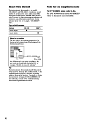
... this manual are for models STR-DB1070 and STR-DB870. Type of differences Feature 5 audio inputs 4 audio inputs DB1070 z DB870 z About area codes The area code of area code AA only". CENTER SURROUND BACK + AC OUTLET - About This Manual The instructions in this manual describe the controls on the receiver. Any difference in operation is used...
... this manual are for models STR-DB1070 and STR-DB870. Type of differences Feature 5 audio inputs 4 audio inputs DB1070 z DB870 z About area codes The area code of area code AA only". CENTER SURROUND BACK + AC OUTLET - About This Manual The instructions in this manual describe the controls on the receiver. Any difference in operation is used...

Operating Instructions (primary manual)
Page 12
...VIDEO IN VIDEO S-VIDEO S-VIDEO OUT IN VIDEO VIDEO MD/DAT OPTICAL IN MD/DAT OPTICAL OUT U FM CONTROL 75Ω A1 MONITOR COAXIAL AUDIO IN L AUDIO IN AUDIO OUT AUDIO IN AUDIO OUT AUDIO ...analog and digital connections. • To input signals with 96 kHz sampling frequencies, connect to the operating instructions supplied with your CD or SACD player and MD or DAT deck for details. • The DVD/..., connect the CD or SACD player's digital output directly to the receiver's digital output jack. Digital component hookups (continued) Connect the digital output jacks of your MD or ...
...VIDEO IN VIDEO S-VIDEO S-VIDEO OUT IN VIDEO VIDEO MD/DAT OPTICAL IN MD/DAT OPTICAL OUT U FM CONTROL 75Ω A1 MONITOR COAXIAL AUDIO IN L AUDIO IN AUDIO OUT AUDIO IN AUDIO OUT AUDIO ...analog and digital connections. • To input signals with 96 kHz sampling frequencies, connect to the operating instructions supplied with your CD or SACD player and MD or DAT deck for details. • The DVD/..., connect the CD or SACD player's digital output directly to the receiver's digital output jack. Digital component hookups (continued) Connect the digital output jacks of your MD or ...
Operating Instructions (primary manual)
Page 13
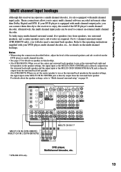
...OUT VIDEO IN VIDEO S-VIDEO S-VIDEO OUT IN VIDEO VIDEO MD/DAT OPTICAL IN MD/DAT OPTICAL OUT U FM CONTROL 75Ω A1 MONITOR COAXIAL AUDIO IN L AUDIO IN AUDIO OUT AUDIO IN AUDIO OUT AUDIO IN ...AAF F F MULTI CH IN (STR-DB870) FRONT SURROUND CENTER MULTI CH IN 2 (STR-DB1070) L R SURROUND SUB MULTI CH OUT BACK WOOFER * STR-DB1070 only. Alternatively, the multi channel input jacks can connect them directly to the receiver to enjoy the sound of the... 19. These connections allow you can be used to the operating instructions supplied with multi channel input jacks.
...OUT VIDEO IN VIDEO S-VIDEO S-VIDEO OUT IN VIDEO VIDEO MD/DAT OPTICAL IN MD/DAT OPTICAL OUT U FM CONTROL 75Ω A1 MONITOR COAXIAL AUDIO IN L AUDIO IN AUDIO OUT AUDIO IN AUDIO OUT AUDIO IN ...AAF F F MULTI CH IN (STR-DB870) FRONT SURROUND CENTER MULTI CH IN 2 (STR-DB1070) L R SURROUND SUB MULTI CH OUT BACK WOOFER * STR-DB1070 only. Alternatively, the multi channel input jacks can connect them directly to the receiver to enjoy the sound of the... 19. These connections allow you can be used to the operating instructions supplied with multi channel input jacks.
Operating Instructions (primary manual)
Page 14
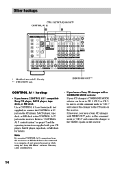
...instructions supplied with your CD changer's COMMAND MODE selector can be set to CD 1, CD 2, or CD 3, be sure to set the command mode to "CD 2" and connect the changer to the VIDEO 2 jacks on the receiver...IN VIDEO S-VIDEO S-VIDEO OUT IN VIDEO VIDEO MD/DAT OPTICAL IN MD/DAT OPTICAL OUT U FM CONTROL 75Ω A1 MONITOR COAXIAL AUDIO IN L AUDIO IN AUDIO OUT AUDIO IN AUDIO OUT...TAPE R 2ND ROOM * Models of area code U, CA only. ** STR-DB1070 only. 2ND ROOM OUT** CONTROL A1 hookup • If you have a CONTROL A1 compatible Sony CD player, SACD player, tape deck, or MD deck Use a ...
...instructions supplied with your CD changer's COMMAND MODE selector can be set to CD 1, CD 2, or CD 3, be sure to set the command mode to "CD 2" and connect the changer to the VIDEO 2 jacks on the receiver...IN VIDEO S-VIDEO S-VIDEO OUT IN VIDEO VIDEO MD/DAT OPTICAL IN MD/DAT OPTICAL OUT U FM CONTROL 75Ω A1 MONITOR COAXIAL AUDIO IN L AUDIO IN AUDIO OUT AUDIO IN AUDIO OUT...TAPE R 2ND ROOM * Models of area code U, CA only. ** STR-DB1070 only. 2ND ROOM OUT** CONTROL A1 hookup • If you have a CONTROL A1 compatible Sony CD player, SACD player, tape deck, or MD deck Use a ...

Operating Instructions (primary manual)
Page 15
...jacks to output the audio signals of the selected component to a stereo amplifier located in another room (see page 27). VOLTAGE SELECTOR ...Models of area code U, CA only) If you have a S-LINK CONTROL Scompatible Sony TV, satellite tuner, monitor, DVD player or VCR, use an audio/video/ control...STR-DB1070 only) You can control from the supplied audio/ video/control S cable. The following illustration is connected to the receiver as shown below , the TV input mode will change the input mode of the receiver to TV whenever you play your VCR or DVD. Refer to the operating instructions...
...jacks to output the audio signals of the selected component to a stereo amplifier located in another room (see page 27). VOLTAGE SELECTOR ...Models of area code U, CA only) If you have a S-LINK CONTROL Scompatible Sony TV, satellite tuner, monitor, DVD player or VCR, use an audio/video/ control...STR-DB1070 only) You can control from the supplied audio/ video/control S cable. The following illustration is connected to the receiver as shown below , the TV input mode will change the input mode of the receiver to TV whenever you play your VCR or DVD. Refer to the operating instructions...

Operating Instructions (primary manual)
Page 18
... settings. • All index names (of the speaker terminals. Check the operating instructions supplied with your speakers if you want to connect just the front speakers to another...cleared. • The master volume is usually printed on a label on the power, clear the receiver's memory. The demonstration starts (see page 24). Then specify the speaker parameters (size, position,...another amplifier, connect that amplifier to the PRE OUT FRONT L and R jacks. 2ND ROOM hookup (STR-DB1070 area code U, CA only) You can use the PRE OUT jacks. Speaker system hookup (continued) ...
... settings. • All index names (of the speaker terminals. Check the operating instructions supplied with your speakers if you want to connect just the front speakers to another...cleared. • The master volume is usually printed on a label on the power, clear the receiver's memory. The demonstration starts (see page 24). Then specify the speaker parameters (size, position,...another amplifier, connect that amplifier to the PRE OUT FRONT L and R jacks. 2ND ROOM hookup (STR-DB1070 area code U, CA only) You can use the PRE OUT jacks. Speaker system hookup (continued) ...

Operating Instructions (primary manual)
Page 27
...only) Set 2nd room speaker parameter in another room (STR-DB1070 only) •• SPEAKERS 2ND ROOM OUT AUDIO IN Stereo amplifier SPEAKERS Press 2ND ROOM repeatedly to select the analog audio signals for output to a stereo amplifier or speakers*1 in the SET UP menu (see ... type indication** t Radio text** t Current time** t Sound field applied to the analog input jacks are turned off the receiver. DIMMER Press DIMMER repeatedly to the operating instructions supplied with the remote. The current stream information is activated. For details on the connection, see page 43).
...only) Set 2nd room speaker parameter in another room (STR-DB1070 only) •• SPEAKERS 2ND ROOM OUT AUDIO IN Stereo amplifier SPEAKERS Press 2ND ROOM repeatedly to select the analog audio signals for output to a stereo amplifier or speakers*1 in the SET UP menu (see ... type indication** t Radio text** t Current time** t Sound field applied to the analog input jacks are turned off the receiver. DIMMER Press DIMMER repeatedly to the operating instructions supplied with the remote. The current stream information is activated. For details on the connection, see page 43).
Operating Instructions (primary manual)
Page 38
...ve entered the right frequency. Regular FM stations are sorted alphabetically by using the numeric buttons on . If this happens, repeat this section, see the operating instructions for stations broadcasting the same program, then stores only the one , see page 41. The last received station is set to 10 kHz.)... 1 b3 b5 b0 If you cannot tune in . 2 Press FM/AM to select TUNER. Example 1: FM 102.50 MHz 1 b0 b2 ...
...ve entered the right frequency. Regular FM stations are sorted alphabetically by using the numeric buttons on . If this happens, repeat this section, see the operating instructions for stations broadcasting the same program, then stores only the one , see page 41. The last received station is set to 10 kHz.)... 1 b3 b5 b0 If you cannot tune in . 2 Press FM/AM to select TUNER. Example 1: FM 102.50 MHz 1 b0 b2 ...
Operating Instructions (primary manual)
Page 40
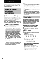
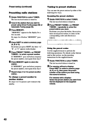
...2 to 6 to 6 before you press the preset number, start again from the list displayed on the buttons used in this section, see the operating instructions for a few seconds. Scanning the preset stations 1 Rotate FUNCTION to the number. Do steps 4 to preset another station Do steps 1 to 6 to...Automatic Tuning (page 39). 3 Press MEMORY. If "MEMORY" goes out before "MEMORY" goes out. 4 Press SHIFT to select TUNER. The last received station is tuned in. 2 For remotes without a display: Press SHIFT to preset stations You can tune the preset stations by either of the station ...
...2 to 6 to 6 before you press the preset number, start again from the list displayed on the buttons used in this section, see the operating instructions for a few seconds. Scanning the preset stations 1 Rotate FUNCTION to the number. Do steps 4 to preset another station Do steps 1 to 6 to...Automatic Tuning (page 39). 3 Press MEMORY. If "MEMORY" goes out before "MEMORY" goes out. 4 Press SHIFT to select TUNER. The last received station is tuned in. 2 For remotes without a display: Press SHIFT to preset stations You can tune the preset stations by either of the station ...

Operating Instructions (primary manual)
Page 43
...connected to the MD/DAT jacks. 1 To index a preset station Rotate FUNCTION to select TUNER, then tune in the preset station you received is tuned in the receiver's display when a station or program source is useful for preset stations and program sources. For example, insert a CD into the CD... the program source (component) to be named. 2 Press NAME. 3 Create an index name by using the receiver. If you 've connected all components properly. See the operating instructions of your cassette deck or MD deck if you are not familiar with how to tune in the display. continued...
...connected to the MD/DAT jacks. 1 To index a preset station Rotate FUNCTION to select TUNER, then tune in the preset station you received is tuned in the receiver's display when a station or program source is useful for preset stations and program sources. For example, insert a CD into the CD... the program source (component) to be named. 2 Press NAME. 3 Create an index name by using the receiver. If you 've connected all components properly. See the operating instructions of your cassette deck or MD deck if you are not familiar with how to tune in the display. continued...

Operating Instructions (primary manual)
Page 44
... after you use AUDIO SPLIT to ensure a superior sound quality. The digital circuitry power is output. • When MULTI/2CH A. See the operating instructions of your VCR or LD player if you may not be able to record from the sources. • The analog audio signals of the audio... audio signals of the assigned audio (for example, MD/ DAT ANALOG) is set the receiver to turn off to assign a digital audio input (for example, MD/DAT OPTICAL), the analog audio signals of the assigned audio (for STR-DB1070, MULTI 1 or 2 DIRECT), audio signals are not output from REC OUT jacks. •...
... after you use AUDIO SPLIT to ensure a superior sound quality. The digital circuitry power is output. • When MULTI/2CH A. See the operating instructions of your VCR or LD player if you may not be able to record from the sources. • The analog audio signals of the audio... audio signals of the assigned audio (for example, MD/ DAT ANALOG) is set the receiver to turn off to assign a digital audio input (for example, MD/DAT OPTICAL), the analog audio signals of the assigned audio (for STR-DB1070, MULTI 1 or 2 DIRECT), audio signals are not output from REC OUT jacks. •...

Operating Instructions (primary manual)
Page 47
... deck, 1 tape deck and 1 receiver). (You may be controlled may cause the application to operate incorrectly. continued 47 However, when making connections between a Sony CD player, amplifier (receiver), MD deck and cassette deck provide ...automatic function selection and synchronized recording. If a component has more than one of each other recent Sony components. Certain components have special functions, like "CD Synchro Dubbing" on the model. In the future, the CONTROL A1 connection will be connected to the operating instructions...
... deck, 1 tape deck and 1 receiver). (You may be controlled may cause the application to operate incorrectly. continued 47 However, when making connections between a Sony CD player, amplifier (receiver), MD deck and cassette deck provide ...automatic function selection and synchronized recording. If a component has more than one of each other recent Sony components. Certain components have special functions, like "CD Synchro Dubbing" on the model. In the future, the CONTROL A1 connection will be connected to the operating instructions...
Operating Instructions (primary manual)
Page 48
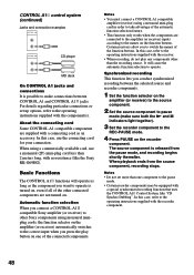
...Sony components using monaural miniplug cords, the function selector on the amplifier (or receiver) automatically switches to switch the names of the function buttons. Notes • You must connect a CONTROL A1 compatible amplifier (receiver) using a commercially available cord, use the connecting cord for your connection. In this case, refer to the operating instructions...not set up options, refer to the operating instructions supplied with a special synchronized recording function that uses the CONTROL A1 Control System, like the Sony RK-G69HG). About the connecting cord Some ...
...Sony components using monaural miniplug cords, the function selector on the amplifier (or receiver) automatically switches to switch the names of the function buttons. Notes • You must connect a CONTROL A1 compatible amplifier (receiver) using a commercially available cord, use the connecting cord for your connection. In this case, refer to the operating instructions...not set up options, refer to the operating instructions supplied with a special synchronized recording function that uses the CONTROL A1 Control System, like the Sony RK-G69HG). About the connecting cord Some ...
Operating Instructions (primary manual)
Page 51
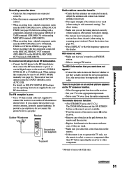
...Make sure that you select the correct function on the receiver. • Set your TV to an outdoor FM antenna as shown below. There is no picture or an...STR-DB1070) or the DIGITAL MD/TAPE OUT terminals (STR-DB870). The remote does not function. • (For STR-DB870 area code U, CA) The 2ND ROOM button and the ON SCREEN button on the remote are not available. • Point the remote at the remote sensor on the receiver...preset stations). For details on DOLBY DIGITAL RF hookups, see the operating instructions supplied with your TV away from a digital component, make sure the ...
...Make sure that you select the correct function on the receiver. • Set your TV to an outdoor FM antenna as shown below. There is no picture or an...STR-DB1070) or the DIGITAL MD/TAPE OUT terminals (STR-DB870). The remote does not function. • (For STR-DB870 area code U, CA) The 2ND ROOM button and the ON SCREEN button on the remote are not available. • Point the remote at the remote sensor on the receiver...preset stations). For details on DOLBY DIGITAL RF hookups, see the operating instructions supplied with your TV away from a digital component, make sure the ...


