Operation Manual
Page 11
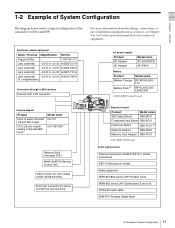
...Pull Down Board Network Adaptor CBK-FC01 2) CBK-NC01 Memory Card Adaptor CBK-PC01 2) For PDW-510/530 only Audio signal source External microphone ECM-670/678 or similar microphone CAC-12 Microphone ...CCXA-53 audio cable DMX-P01 Portable Digital Mixer 11 1-2 Example of additional equipment and accessories, see Chapter 9 as well as the operation manuals for ENG and EFP. Fog-proof filter - 1-547-341-11 Lens assembly -2.8 D to +2.0 D A-8262-537-A Lens assembly -3.6... System Configuration The diagram below shows a typical configuration of the camcorder for the connected equipment.
...Pull Down Board Network Adaptor CBK-FC01 2) CBK-NC01 Memory Card Adaptor CBK-PC01 2) For PDW-510/530 only Audio signal source External microphone ECM-670/678 or similar microphone CAC-12 Microphone ...CCXA-53 audio cable DMX-P01 Portable Digital Mixer 11 1-2 Example of additional equipment and accessories, see Chapter 9 as well as the operation manuals for ENG and EFP. Fog-proof filter - 1-547-341-11 Lens assembly -2.8 D to +2.0 D A-8262-537-A Lens assembly -3.6... System Configuration The diagram below shows a typical configuration of the camcorder for the connected equipment.
Operation Manual
Page 34
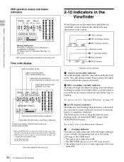
...when the time code or real time is detected. c BATT (battery) indicator This indicator starts flashing when the battery connected to the Maintenance Manual. The battery power level at which the indicator starts flashing can be set on page 174. LED page of the USER menu. •... Warning display area This shows a message if a recording fault or condensation is displayed. Lights in non-drop frame mode. (PDW-510/530 only) Lights when the camcorder is received from the camera control unit and flashes to indicate the current state and adjustments of the camera. 1 TALLY indicator ...
...when the time code or real time is detected. c BATT (battery) indicator This indicator starts flashing when the battery connected to the Maintenance Manual. The battery power level at which the indicator starts flashing can be set on page 174. LED page of the USER menu. •... Warning display area This shows a message if a recording fault or condensation is displayed. Lights in non-drop frame mode. (PDW-510/530 only) Lights when the camcorder is received from the camera control unit and flashes to indicate the current state and adjustments of the camera. 1 TALLY indicator ...
Operation Manual
Page 87
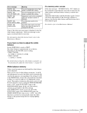
... white video level is turned on the FILTER selector setting. • PDW-530/530P: B: 3200K, C: 4300 K, D: 6300K • PDW-510/510P: 1: 3200 K, 3: 5600 K For details about this internal check, refer to the Maintenance Manual. In this message continues to appear even after the white balance and ... automatically adjust the white balance" on the viewfinder screen when the camcorder is too high. For details, refer to each of the filters can be completed within the standard number of attempts. Contact your Sony representative if this case, the memory contents are two sets of ...
... white video level is turned on the FILTER selector setting. • PDW-530/530P: B: 3200K, C: 4300 K, D: 6300K • PDW-510/510P: 1: 3200 K, 3: 5600 K For details about this internal check, refer to the Maintenance Manual. In this message continues to appear even after the white balance and ... automatically adjust the white balance" on the viewfinder screen when the camcorder is too high. For details, refer to each of the filters can be completed within the standard number of attempts. Contact your Sony representative if this case, the memory contents are two sets of ...

Operation Manual
Page 98
...item to "ON" on the GENLOCK page of the MAINTENANCE menu. However, there will show the value of the camcorder, the camera cannot be correctly genlocked. Therefore, the user bits can have their own settings for a few seconds... synchronized with the external time code and the counter display will be synchronized with the SMPTE (for PDW-510/530) or EBU (for PDW-510P/530P) standard and in proper phase relationship, to the TC IN connector and to the GENLOCK... maintain a continuous power supply, connect the external power supply to the Maintenance Manual. However, wait for each camcorder.
...item to "ON" on the GENLOCK page of the MAINTENANCE menu. However, there will show the value of the camcorder, the camera cannot be correctly genlocked. Therefore, the user bits can have their own settings for a few seconds... synchronized with the external time code and the counter display will be synchronized with the SMPTE (for PDW-510/530) or EBU (for PDW-510P/530P) standard and in proper phase relationship, to the TC IN connector and to the GENLOCK... maintain a continuous power supply, connect the external power supply to the Maintenance Manual. However, wait for each camcorder.
Operation Manual
Page 170
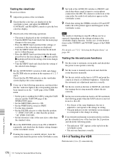
...zoom mode and check that the power zoom operates correctly. 2 Set the zoom to manual zoom mode and check the zoom functions manually. 3 Set the iris switch on the viewfinder screen. • The auto iris ...the lens extender. • Set the FILTER selector to other than the position "1" (PDW-510/510P) or other than the position "1B" (PDW-530/530P). • Set the reference value of the auto iris to other than...the setting of different brightness. Chapter 10 Maintenance 170 10-1 Testing the Camcorder Before Shooting In this case, set the desired items on the VF DISP 1 and VF DISP 2 ...
...zoom mode and check that the power zoom operates correctly. 2 Set the zoom to manual zoom mode and check the zoom functions manually. 3 Set the iris switch on the viewfinder screen. • The auto iris ...the lens extender. • Set the FILTER selector to other than the position "1" (PDW-510/510P) or other than the position "1B" (PDW-530/530P). • Set the reference value of the auto iris to other than...the setting of different brightness. Chapter 10 Maintenance 170 10-1 Testing the Camcorder Before Shooting In this case, set the desired items on the VF DISP 1 and VF DISP 2 ...
Operation Manual
Page 179
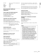
... supply and related equipment BP- Appendixes DC OUT LENS REMOTE LIGHT i.LINK 4-pin, 11 to the camcorder. A-8262-538- SONY WILL NOT BE LIABLE FOR DAMAGES OF ANY KIND INCLUDING, BUT NOT LIMITED TO, COMPENSATION OR REIMBURSEMENT ON...Extension boards CBK-SD01 SDI Output Board CBK-SC01 Composite Input Board CBK-FC01 Pull Down Board (for the PDW-510/530 only) CBK-NC01 Network Adaptor CBK-PC01 Memory Card Adaptor Equipment for converting 5-pin connector to change without... LC-DS300SFT Soft Carrying Case Tripod Adaptor VCT-14 Maintenance Manual Design and specifications are male and 5pin.
... supply and related equipment BP- Appendixes DC OUT LENS REMOTE LIGHT i.LINK 4-pin, 11 to the camcorder. A-8262-538- SONY WILL NOT BE LIABLE FOR DAMAGES OF ANY KIND INCLUDING, BUT NOT LIMITED TO, COMPENSATION OR REIMBURSEMENT ON...Extension boards CBK-SD01 SDI Output Board CBK-SC01 Composite Input Board CBK-FC01 Pull Down Board (for the PDW-510/530 only) CBK-NC01 Network Adaptor CBK-PC01 Memory Card Adaptor Equipment for converting 5-pin connector to change without... LC-DS300SFT Soft Carrying Case Tripod Adaptor VCT-14 Maintenance Manual Design and specifications are male and 5pin.


