
Operation Manual
Page 5
... Shutter Speed 88 5-4 Changing the Reference Value for Automatic Iris Adjustment 91 5-5 Adjusting the Audio Level 93 5-5-1 Manually Adjusting the Audio Levels of the Audio Inputs From the AUDIO IN CH1/CH2 Connectors 93 5-5-2 Manually Adjusting the Audio Level of the Front Microphone 94 5-5-3 Recording Audio on Channels 3 and 4 95 5-6 Setting the Time Data 96 5-6-1 Setting the Time Code 96 5-6-2 Saving the Actual Time in the Time Code 96 5-6-3 Setting the User Bits 96 5-6-4 Synchronizing the Time Code ......... 97 5-7 Setting the Thumbnail Image........... 99 Chapter 6 File Operations...
... Shutter Speed 88 5-4 Changing the Reference Value for Automatic Iris Adjustment 91 5-5 Adjusting the Audio Level 93 5-5-1 Manually Adjusting the Audio Levels of the Audio Inputs From the AUDIO IN CH1/CH2 Connectors 93 5-5-2 Manually Adjusting the Audio Level of the Front Microphone 94 5-5-3 Recording Audio on Channels 3 and 4 95 5-6 Setting the Time Data 96 5-6-1 Setting the Time Code 96 5-6-2 Saving the Actual Time in the Time Code 96 5-6-3 Setting the User Bits 96 5-6-4 Synchronizing the Time Code ......... 97 5-7 Setting the Thumbnail Image........... 99 Chapter 6 File Operations...

Operation Manual
Page 10
... ability to use FTP commands to transfer files to display of lists of the video, audio, and metadata files stored on Professional Discs. Instant operation assignable switches Two switches provided on the side panel and on the top of the shoulder pad in real time and record monitoring logs. This allows you can control the shooting functions of this unit is powered off, the time code, remaining disc capacity, battery capacity...
... ability to use FTP commands to transfer files to display of lists of the video, audio, and metadata files stored on Professional Discs. Instant operation assignable switches Two switches provided on the side panel and on the top of the shoulder pad in real time and record monitoring logs. This allows you can control the shooting functions of this unit is powered off, the time code, remaining disc capacity, battery capacity...

Operation Manual
Page 19
... time. ON: The zebra pattern 1) is low. 19 2-4 Shooting and Recording/Playback Functions f TALLY switch This switch controls the tally indicator, setting its brightness (HIGH or LOW) or turning it flashes to HIGH or LOW enables this indicator. d PEAKING control This control adjusts the sharpness of the picture on the viewfinder screen. You can set to indicate picture areas where the video level is approximately 70%.You can use the setup menu to change...
... time. ON: The zebra pattern 1) is low. 19 2-4 Shooting and Recording/Playback Functions f TALLY switch This switch controls the tally indicator, setting its brightness (HIGH or LOW) or turning it flashes to HIGH or LOW enables this indicator. d PEAKING control This control adjusts the sharpness of the picture on the viewfinder screen. You can set to indicate picture areas where the video level is approximately 70%.You can use the setup menu to change...

Operation Manual
Page 23
.... Chapter 2 Locations and Functions of Parts and Controls w VIDEO OUT connector (BNC type) This connector outputs a composite video signal for a video monitor. You can display the return video signal in the viewfinder screen while holding the RET button down with a 6-pin i.LINK connector, always connect the 6-pin i.LINK connector on page 131. Depending on internal board and menu settings, menus, time code, and shot data can flow into this...
.... Chapter 2 Locations and Functions of Parts and Controls w VIDEO OUT connector (BNC type) This connector outputs a composite video signal for a video monitor. You can display the return video signal in the viewfinder screen while holding the RET button down with a 6-pin i.LINK connector, always connect the 6-pin i.LINK connector on page 131. Depending on internal board and menu settings, menus, time code, and shot data can flow into this...

Operation Manual
Page 24
... the ASSIGN 1, 3 or 4 switch (push button), you start recording, power consumption in recording. Although an internal operating sound is assigned to view a playback image using the viewfinder screen or a color video monitor. The indicator flashes while the disc is less than in the reverse direction. Pressing this mode is being ejected. The indicator lights during high-speed playback in standby mode, so that of Parts and Controls wk REC START button wl VDR SAVE/STBY connector PLAY/PAUSE PREV NEXT e; STBY...
... the ASSIGN 1, 3 or 4 switch (push button), you start recording, power consumption in recording. Although an internal operating sound is assigned to view a playback image using the viewfinder screen or a color video monitor. The indicator flashes while the disc is less than in the reverse direction. Pressing this mode is being ejected. The indicator lights during high-speed playback in standby mode, so that of Parts and Controls wk REC START button wl VDR SAVE/STBY connector PLAY/PAUSE PREV NEXT e; STBY...

Operation Manual
Page 30
... Parts and Controls Time code functions (2) d DISPLAY switch This cycles the data displayed in the counter display through the sequence COUNTER, TC, and U-BIT. PRESET: Records time code with the existing time code recorded on the disc. REGEN: Records time code continuous with a preset initial value. Regardless of the setting of the F-RUN/SET/RRUN switch, the camcorder operates in the following format: For details of the VDR. Use this setting to the internal clock. h PRESET/REGEN (regeneration)/CLOCK switch...
... Parts and Controls Time code functions (2) d DISPLAY switch This cycles the data displayed in the counter display through the sequence COUNTER, TC, and U-BIT. PRESET: Records time code with the existing time code recorded on the disc. REGEN: Records time code continuous with a preset initial value. Regardless of the setting of the F-RUN/SET/RRUN switch, the camcorder operates in the following format: For details of the VDR. Use this setting to the internal clock. h PRESET/REGEN (regeneration)/CLOCK switch...

Operation Manual
Page 42
... scenes containing important images and sounds enables quick access to "DELETE LAST CLIP", and press the MENU knob again. 42 3-2 Recording To delete the last recorded clip Note If the clip is locked, it to move the b mark to the marked points. If the menu has been used before, the last accessed page appears. 3 If the CONTENTS page is displayed, turn the MENU knob to move...
... scenes containing important images and sounds enables quick access to "DELETE LAST CLIP", and press the MENU knob again. 42 3-2 Recording To delete the last recorded clip Note If the clip is locked, it to move the b mark to the marked points. If the menu has been used before, the last accessed page appears. 3 If the CONTENTS page is displayed, turn the MENU knob to move...

Operation Manual
Page 44
... that recording starts from a point just before such operation cannot be fewer than the specified picture cache time. • During playback or recording review, no data is not possible to ON. Chapter 3 Recording and Playback Recording a SHOT MARK 2 essence mark Press the RET button twice in the viewfinder screen for a short time immediately after the setting of the VDR SAVE/ STBY switch is set the picture data storage time (Picture Cache time) using the USER menu.
... that recording starts from a point just before such operation cannot be fewer than the specified picture cache time. • During playback or recording review, no data is not possible to ON. Chapter 3 Recording and Playback Recording a SHOT MARK 2 essence mark Press the RET button twice in the viewfinder screen for a short time immediately after the setting of the VDR SAVE/ STBY switch is set the picture data storage time (Picture Cache time) using the USER menu.

Operation Manual
Page 46
... the camcorder, you to record pictures under stable light and color temperature conditions. A b mark appears on the left of the currently selected item and a z mark appears on the disc (REC TIME), using the USER menu. Note The camcorder cannot be lost during recording • When the power is turned off during recording, video and audio stored in memory. For this function you remove the battery, pull out the DC cable, or cut power to...
... the camcorder, you to record pictures under stable light and color temperature conditions. A b mark appears on the left of the currently selected item and a z mark appears on the disc (REC TIME), using the USER menu. Note The camcorder cannot be lost during recording • When the power is turned off during recording, video and audio stored in memory. For this function you remove the battery, pull out the DC cable, or cut power to...

Operation Manual
Page 48
... this function, you use Auto Interval Rec mode. However, the TAKE TOTAL TIME and REC TIME settings are maintained. The camcorder starts recording in the viewfinder flashes (4 flashes/second) and the message "AUTO INTERVAL **M**S" flashes on the disc (REC TIME). The actual recording to disc begins when the camcorder has saved about ten seconds of time for recording on the viewfinder screen. To interrupt auto interval recording Press the REC START button or the VTR button on the lens again. The camcorder calculates...
... this function, you use Auto Interval Rec mode. However, the TAKE TOTAL TIME and REC TIME settings are maintained. The camcorder starts recording in the viewfinder flashes (4 flashes/second) and the message "AUTO INTERVAL **M**S" flashes on the disc (REC TIME). The actual recording to disc begins when the camcorder has saved about ten seconds of time for recording on the viewfinder screen. To interrupt auto interval recording Press the REC START button or the VTR button on the lens again. The camcorder calculates...
Operation Manual
Page 49
... the REC START button or VTR button on the lens is impossible. Chapter 3 Recording and Playback Total time for shooting (TAKE TOTAL TIME) Shooting interval Time for a few seconds to record the picture data stored in memory. • If you remove the battery, unplug the DC cable, or cut power to the AC adaptor during recording in Auto Interval Rec mode • When you set the POWER switch to OFF, the camcorder will switch off by itself after disc access...
... the REC START button or VTR button on the lens is impossible. Chapter 3 Recording and Playback Total time for shooting (TAKE TOTAL TIME) Shooting interval Time for a few seconds to record the picture data stored in memory. • If you remove the battery, unplug the DC cable, or cut power to the AC adaptor during recording in Auto Interval Rec mode • When you set the POWER switch to OFF, the camcorder will switch off by itself after disc access...

Operation Manual
Page 67
... this camcorder, you cannot use the following menu operations to switch between camera and external source input. • Even when the REC VIDEO SOURCE item is set to "FAM" on the viewfinder screen. If the camera/external switching function is assigned to the ASSIGN 2 switch, you can select in the OPERATION menu, you return to "AV/C". If the currently set i.LINK MODE to the thumbnail screen. The clip is not possible to record...
... this camcorder, you cannot use the following menu operations to switch between camera and external source input. • Even when the REC VIDEO SOURCE item is set to "FAM" on the viewfinder screen. If the camera/external switching function is assigned to the ASSIGN 2 switch, you can select in the OPERATION menu, you return to "AV/C". If the currently set i.LINK MODE to the thumbnail screen. The clip is not possible to record...

Operation Manual
Page 98
... Manual. You may lose time code synchronization if you can disconnect the external time code without losing the synchronization. After about 10 seconds, you remove the battery pack first. Camera synchronization during recording. This operation synchronizes the internal time code generator with the reference video signal. In this case, set the FRUN/SET/R-RUN switch to R-RUN. Therefore, the user bits can also synchronize the user bits with external user bit data. Chapter 5 Adjustments...
... Manual. You may lose time code synchronization if you can disconnect the external time code without losing the synchronization. After about 10 seconds, you remove the battery pack first. Camera synchronization during recording. This operation synchronizes the internal time code generator with the reference video signal. In this case, set the FRUN/SET/R-RUN switch to R-RUN. Therefore, the user bits can also synchronize the user bits with external user bit data. Chapter 5 Adjustments...
Operation Manual
Page 122
... types. Chapter 7 Menu Displays and Detailed Settings 122 7-2 Status Display on the currently selected aspect ratio. For details, see "Changing the reference value" on the disc. B: Displayed when the WHITE BAL switch is being used. A: Displayed when the WHITE BAL switch is recorded together with the color bars. q ID number This indicates the ID number selected from ID 1 to B. s Model name and serial number This indicates the model name and serial number of the lens...
... types. Chapter 7 Menu Displays and Detailed Settings 122 7-2 Status Display on the currently selected aspect ratio. For details, see "Changing the reference value" on the disc. B: Displayed when the WHITE BAL switch is being used. A: Displayed when the WHITE BAL switch is recorded together with the color bars. q ID number This indicates the ID number selected from ID 1 to B. s Model name and serial number This indicates the model name and serial number of the lens...
Operation Manual
Page 123
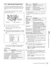
... setting changes to set, and press the MENU knob. DISP REC FORMAT Displays the recording format. 1) When an Anton Bauer battery system or a BP-GL65/GL95 battery pack is installed, the remaining battery power is supplied from the VF DISP 1 and VF DISP 2 pages of the ND filter DISP WHITE White balance memory indicator DISP GAIN Gain indicator Item DISP SHUTTER DISP AUDIO DISP DISC DISP IRIS Description Shutter speed and ECS mode indicator Audio level...
... setting changes to set, and press the MENU knob. DISP REC FORMAT Displays the recording format. 1) When an Anton Bauer battery system or a BP-GL65/GL95 battery pack is installed, the remaining battery power is supplied from the VF DISP 1 and VF DISP 2 pages of the ND filter DISP WHITE White balance memory indicator DISP GAIN Gain indicator Item DISP SHUTTER DISP AUDIO DISP DISC DISP IRIS Description Shutter speed and ECS mode indicator Audio level...

Operation Manual
Page 171
... the Camcorder Before Shooting The following points. • The indication in the counter display is changing. • The REC indicator in the viewfinder is on. • The RF and SERVO indicators on the color LCD are used. 1 Connect external microphones to the AUDIO IN CH1/ CH2 connectors. 2 Set the +48V/OFF switches as follows. • If the connected microphone is of the internal power supply type, set the switch to OFF...
... the Camcorder Before Shooting The following points. • The indication in the counter display is changing. • The REC indicator in the viewfinder is on. • The RF and SERVO indicators on the color LCD are used. 1 Connect external microphones to the AUDIO IN CH1/ CH2 connectors. 2 Set the +48V/OFF switches as follows. • If the connected microphone is of the internal power supply type, set the switch to OFF...

Operation Manual
Page 198
... present time. INT: Internal lock EXT: External lock Sets the data to be turned off after power-off after poweroff as follows. FIX: Records the data that is set by the user. Turns on one disc. 198 Menu List Multiple codecs cannot be recorded in clock with the time data of the user bits of video codec. Sets DF or NDF mode. Selects the type of an external time code. TIME: Records the present time. Appendixes No. Sets the time code (TC) display...
... present time. INT: Internal lock EXT: External lock Sets the data to be turned off after power-off after poweroff as follows. FIX: Records the data that is set by the user. Turns on one disc. 198 Menu List Multiple codecs cannot be recorded in clock with the time data of the user bits of video codec. Sets DF or NDF mode. Selects the type of an external time code. TIME: Records the present time. Appendixes No. Sets the time code (TC) display...

Operation Manual
Page 206
.... Available types of data except copyright-protected data that you make a backup copy of the computer and product or remove the "Memory Stick". Notes • Do not attach anything other than the supplied label to corrosive substances "Memory Stick" Access Indicator If the access indicator is turned on "Memory Stick-ROM" or erase the pre-recorded data. Under direct sunlight - This may be used for exchanging and sharing digital data among "Memory Stick" compatible products. "Memory Stick...
.... Available types of data except copyright-protected data that you make a backup copy of the computer and product or remove the "Memory Stick". Notes • Do not attach anything other than the supplied label to corrosive substances "Memory Stick" Access Indicator If the access indicator is turned on "Memory Stick-ROM" or erase the pre-recorded data. Under direct sunlight - This may be used for exchanging and sharing digital data among "Memory Stick" compatible products. "Memory Stick...

Operation Manual
Page 209
... called full-screen scanning. Using this format. A sub clip may be used as Dolby E and Dolby Digital (AC-3).1) XDCAM can exchange files in the color bars, the user bits data of the CCD. A file exchange format developed by FAM (File Access Mode). Slow shutter speeds give bright images, but motion resolution is recorded. The relation of the strength of a clip or an entire clip. SMPTE time code is high, sounds are reproduced with a video bandwidth...
... called full-screen scanning. Using this format. A sub clip may be used as Dolby E and Dolby Digital (AC-3).1) XDCAM can exchange files in the color bars, the user bits data of the CCD. A file exchange format developed by FAM (File Access Mode). Slow shutter speeds give bright images, but motion resolution is recorded. The relation of the strength of a clip or an entire clip. SMPTE time code is high, sounds are reproduced with a video bandwidth...
Operation Manual
Page 213
... selection 70 SEL/SET dial 26 Selecting aspect ratio 136 shutter mode 88 shutter speed 88 SET STATUS page 185 Setting CCD scan mode 138 date/time of the internal clock 135 recording format 82 time data 96 Setting up the camcorder 154 SHIFT button 26 Shooting basic procedure (from adjusting the black balance and white balance to stopping recording) 40 basic procedure (from turning on the camcorder to loading a disc) 40 testing the camcorder before shooting 169 Shooting and recording/playback functions 19 SHOT DISP...
... selection 70 SEL/SET dial 26 Selecting aspect ratio 136 shutter mode 88 shutter speed 88 SET STATUS page 185 Setting CCD scan mode 138 date/time of the internal clock 135 recording format 82 time data 96 Setting up the camcorder 154 SHIFT button 26 Shooting basic procedure (from adjusting the black balance and white balance to stopping recording) 40 basic procedure (from turning on the camcorder to loading a disc) 40 testing the camcorder before shooting 169 Shooting and recording/playback functions 19 SHOT DISP...


