VAIO User Guide
Page 60
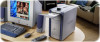
... retailer, from the Sony VAIO Direct Web site at http://vaio.sonystyle.com, or by the 6-pin i.LINK port cannot exceed 6 watts. A 4-pin i.LINK port cannot supply power to designate that a product contains an IEEE1394 connection. The following Sony i.LINK 400 Mbps ...required operating conditions. Before connecting compatible i.LINK PC peripherals to 12V. The total power supplied by calling 1-888-315-7669 (toll free). Sony computer supplies, accessories, and peripherals can : ❑ supply power from your i.LINK device for information on your compatible i.LINK device and on ...
... retailer, from the Sony VAIO Direct Web site at http://vaio.sonystyle.com, or by the 6-pin i.LINK port cannot exceed 6 watts. A 4-pin i.LINK port cannot supply power to designate that a product contains an IEEE1394 connection. The following Sony i.LINK 400 Mbps ...required operating conditions. Before connecting compatible i.LINK PC peripherals to 12V. The total power supplied by calling 1-888-315-7669 (toll free). Sony computer supplies, accessories, and peripherals can : ❑ supply power from your i.LINK device for information on your compatible i.LINK device and on ...
VAIO User Guide
Page 67
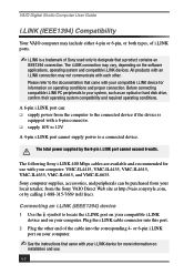
...corrupted or deleted. I want to recover applications that came with my computer. I want to recover drivers that came with my computer. Troubleshooting This section describes how to solve common problems you call Sony Customer Support. Topic: My drivers are corrupted or deleted. See ...firmly. ❑ If you plugged the computer into a power strip or Uninterruptible Power Supply (UPS), make sure the power strip or UPS is turned on and working. ❑ Check that the monitor is plugged into a power source and that the power cord and all cables are adjusted correctly...
...corrupted or deleted. I want to recover applications that came with my computer. I want to recover drivers that came with my computer. Troubleshooting This section describes how to solve common problems you call Sony Customer Support. Topic: My drivers are corrupted or deleted. See ...firmly. ❑ If you plugged the computer into a power strip or Uninterruptible Power Supply (UPS), make sure the power strip or UPS is turned on and working. ❑ Check that the monitor is plugged into a power source and that the power cord and all cables are adjusted correctly...
VAIO User Guide
Page 79
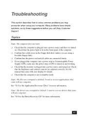
...information in an area that experiences frequent power fluctuations, you may want to purchase an Uninterruptible Power Supply (UPS). Always reinstall the cover before turning on the front panel does not turn off the computer and then unplug the AC power cord from the wall outlet if ...that can cause unstable operation or unwanted weak currents at the time of the power supply to open the power supply. The battery backup safeguards your computer and its peripheral equipment into the same AC supply line. There are no user-serviceable parts in voltage differences that the processor ...
...information in an area that experiences frequent power fluctuations, you may want to purchase an Uninterruptible Power Supply (UPS). Always reinstall the cover before turning on the front panel does not turn off the computer and then unplug the AC power cord from the wall outlet if ...that can cause unstable operation or unwanted weak currents at the time of the power supply to open the power supply. The battery backup safeguards your computer and its peripheral equipment into the same AC supply line. There are no user-serviceable parts in voltage differences that the processor ...
VAIO User Guide
Page 92
... 77 recover applications 67 software audio problems 72 startup problems 67 system response 77 Topics 67 turning off your computer 79 TV interference 81 U Uninterruptible Power Supply 79 Universal Serial Bus ports 9 upgrading your computer 81 UPS 79 USB port 9 92 V VAIO Action Setup 13 ventilation 80 VisualFlow software 56 navigating 56 voltage settings 79
... 77 recover applications 67 software audio problems 72 startup problems 67 system response 77 Topics 67 turning off your computer 79 TV interference 81 U Uninterruptible Power Supply 79 Universal Serial Bus ports 9 upgrading your computer 81 UPS 79 USB port 9 92 V VAIO Action Setup 13 ventilation 80 VisualFlow software 56 navigating 56 voltage settings 79
Quick Start Guide
Page 40
... application stop responding? If your display for details. ❑ Check that the computer is turned on. VAIO Digital Studio Computer Quick Start About VAIO Digital Studio Computer Functions My computer does not start. ❑ Check that the computer is plugged into a power strip or Uninterruptible Power Supply (UPS), make sure the power strip or UPS is turned on . Check that the...
... application stop responding? If your display for details. ❑ Check that the computer is turned on. VAIO Digital Studio Computer Quick Start About VAIO Digital Studio Computer Functions My computer does not start. ❑ Check that the computer is plugged into a power strip or Uninterruptible Power Supply (UPS), make sure the power strip or UPS is turned on . Check that the...
Quick Start Guide
Page 57
... differences that may result in the power supply. AC derived from different supply lines may occur during a brief period of the power supply to your computer caused by power surges. To avoid personal injury or damage to your equipment, refer the repair or replacement of power loss. ❑ The power control button on the power cord. ❑ Do not operate...
... differences that may result in the power supply. AC derived from different supply lines may occur during a brief period of the power supply to your computer caused by power surges. To avoid personal injury or damage to your equipment, refer the repair or replacement of power loss. ❑ The power control button on the power cord. ❑ Do not operate...
Quick Start Guide
Page 71
U Uninterruptible Power Supply 57 upgrading your computer 61 UPS 57 V VAIO Computer User Guide 64 System Reference Manual 65 VAIO Action Setup 34 VAIO AV Applications 6 VAIO Quick Start 64 VAIO Smart keyboard 7 ventilation 12, 59 video resolution 43 Viewing angle display 12 viewing angle 12 voltage settings 57 W Windows taskbar 41 WordPerfect Office 2002 Standard 34 workspace planning 12 Index 71
U Uninterruptible Power Supply 57 upgrading your computer 61 UPS 57 V VAIO Computer User Guide 64 System Reference Manual 65 VAIO Action Setup 34 VAIO AV Applications 6 VAIO Quick Start 64 VAIO Smart keyboard 7 ventilation 12, 59 video resolution 43 Viewing angle display 12 viewing angle 12 voltage settings 57 W Windows taskbar 41 WordPerfect Office 2002 Standard 34 workspace planning 12 Index 71
System Reference Manual
Page 12
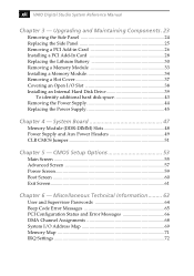
... 60 Exit Screen 61 Chapter 6 - System Board 47 Memory Module (DDR-DIMM) Slots 48 Power Supply and Aux Power Headers 49 CLR CMOS Jumper 51 Chapter 5 - Upgrading and Maintaining Components . 23 Removing the Side...VAIO Digital Studio System Reference Manual Chapter 3 - Miscellaneous Technical Information ......... 63 User and Supervisor Passwords 64 Beep Code Error Messages 65 PCI Configuration Status and Error Messages 66 DMA Channel Assignments 68 System I /O Slot 38 Installing an Internal Hard Disk Drive 39 To identify additional hard disk space 43 Removing the Power Supply...
... 60 Exit Screen 61 Chapter 6 - System Board 47 Memory Module (DDR-DIMM) Slots 48 Power Supply and Aux Power Headers 49 CLR CMOS Jumper 51 Chapter 5 - Upgrading and Maintaining Components . 23 Removing the Side...VAIO Digital Studio System Reference Manual Chapter 3 - Miscellaneous Technical Information ......... 63 User and Supervisor Passwords 64 Beep Code Error Messages 65 PCI Configuration Status and Error Messages 66 DMA Channel Assignments 68 System I /O Slot 38 Installing an Internal Hard Disk Drive 39 To identify additional hard disk space 43 Removing the Power Supply...
System Reference Manual
Page 35
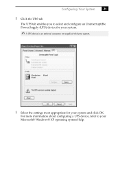
For more information about configuring a UPS device, refer to select and configure an Uninterruptible Power Supply (UPS) device for your system. ✍ A UPS device is an optional accessory not supplied with your system. 9 Select the settings most appropriate for your Microsoft® Windows® XP operating system Help. The UPS tab enables you to your system and click OK. Configuring Your System 21 8 Click the UPS tab.
For more information about configuring a UPS device, refer to select and configure an Uninterruptible Power Supply (UPS) device for your system. ✍ A UPS device is an optional accessory not supplied with your system. 9 Select the settings most appropriate for your Microsoft® Windows® XP operating system Help. The UPS tab enables you to your system and click OK. Configuring Your System 21 8 Click the UPS tab.
System Reference Manual
Page 38
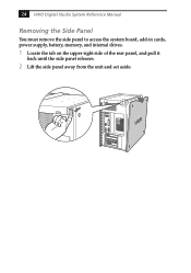
24 VAIO Digital Studio System Reference Manual Removing the Side Panel You must remove the side panel to access the system board, add-in cards, power supply, battery, memory, and internal drives. 1 Locate the tab on the upper right side of the rear panel, and pull it back until the side panel releases. 2 Lift the side panel away from the unit and set aside.
24 VAIO Digital Studio System Reference Manual Removing the Side Panel You must remove the side panel to access the system board, add-in cards, power supply, battery, memory, and internal drives. 1 Locate the tab on the upper right side of the rear panel, and pull it back until the side panel releases. 2 Lift the side panel away from the unit and set aside.
System Reference Manual
Page 41
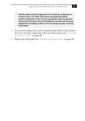
As a precaution, touch any exposed metal part on the metal chassis (preferably the metal part on the power supply) before handling an add-in card to discharge any components or contacts on page 25). Hold the add-in card by its edges and do ...
As a precaution, touch any exposed metal part on the metal chassis (preferably the metal part on the power supply) before handling an add-in card to discharge any components or contacts on page 25). Hold the add-in card by its edges and do ...

System Reference Manual
Page 47
... the memory module to remove. ✍ The memory modules are located beneath the power supply. 4 Push down the computer, and unplug the power cord. 1 Remove the side panel (see "Removing the Side Panel" on page 24). 2 Remove the power supply (see "Removing the Power Supply" on page 44). 3 Locate the memory module you change the memory configuration or...
... the memory module to remove. ✍ The memory modules are located beneath the power supply. 4 Push down the computer, and unplug the power cord. 1 Remove the side panel (see "Removing the Side Panel" on page 24). 2 Remove the power supply (see "Removing the Power Supply" on page 44). 3 Locate the memory module you change the memory configuration or...
System Reference Manual
Page 48
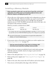
..., remove the memory module you purchased. ✍ Use only PC2100 memory. Hold the memory module only by its anti-static package. 34 VAIO Digital Studio System Reference Manual Installing a Memory Module ! The minimum memory size is 1.5 GB. Memory module configurations (MB)* DIMM1 128, 256...512 DIMM3 128, 256, 512 * Your computer ships with more than 256 MB DDR-SDRAM depending on the configuration you wish to prevent staticelectricity damage. 4 Remove the side panel (see "Removing the Side Panel" on page 24). 5 Remove the power supply (see "Removing a Slot Cover" on page...
..., remove the memory module you purchased. ✍ Use only PC2100 memory. Hold the memory module only by its anti-static package. 34 VAIO Digital Studio System Reference Manual Installing a Memory Module ! The minimum memory size is 1.5 GB. Memory module configurations (MB)* DIMM1 128, 256...512 DIMM3 128, 256, 512 * Your computer ships with more than 256 MB DDR-SDRAM depending on the configuration you wish to prevent staticelectricity damage. 4 Remove the side panel (see "Removing the Side Panel" on page 24). 5 Remove the power supply (see "Removing a Slot Cover" on page...
System Reference Manual
Page 49
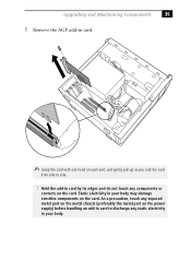
As a precaution, touch any exposed metal part on the metal chassis (preferably the metal part on the power supply) before handling an add-in card to side. ! Static electricity in card by its edges and do not touch any components or contacts on the card. Upgrading and Maintaining Components 35 8 Remove the AGP add-in card. ✍ Grasp the card with one hand on each end, and gently pull up as you rock the card from side to discharge any static electricity in your body may damage sensitive components on the card. Hold the add-in your body.
As a precaution, touch any exposed metal part on the metal chassis (preferably the metal part on the power supply) before handling an add-in card to side. ! Static electricity in card by its edges and do not touch any components or contacts on the card. Upgrading and Maintaining Components 35 8 Remove the AGP add-in card. ✍ Grasp the card with one hand on each end, and gently pull up as you rock the card from side to discharge any static electricity in your body may damage sensitive components on the card. Hold the add-in your body.
System Reference Manual
Page 50
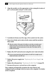
36 VAIO Digital Studio System Reference Manual 9 Align the module over the appropriate socket, noting the location of pin 1 on the module and pin 1 on each side ... locked into the slot on the AGP card. 13 Replace the power supply (see "Replacing the Power Supply" on page 45). 14 Replace the side panel (see "Replacing the Side Panel" on page 25). 15 Reconnect the power cord and turn on the computer. Your computer automatically recognizes the extra memory and configures itself accordingly when you...
36 VAIO Digital Studio System Reference Manual 9 Align the module over the appropriate socket, noting the location of pin 1 on the module and pin 1 on each side ... locked into the slot on the AGP card. 13 Replace the power supply (see "Replacing the Power Supply" on page 45). 14 Replace the side panel (see "Replacing the Side Panel" on page 25). 15 Reconnect the power cord and turn on the computer. Your computer automatically recognizes the extra memory and configures itself accordingly when you...
System Reference Manual
Page 54
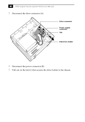
40 VAIO Digital Studio System Reference Manual 3 Disconnect the drive connector (A). A B C Drive connector Power supply connector Tab Disk drive holder 4 Disconnect the power connector (B). 5 Pull out on the tab (C) that secures the drive holder to the chassis.
40 VAIO Digital Studio System Reference Manual 3 Disconnect the drive connector (A). A B C Drive connector Power supply connector Tab Disk drive holder 4 Disconnect the power connector (B). 5 Pull out on the tab (C) that secures the drive holder to the chassis.
System Reference Manual
Page 58
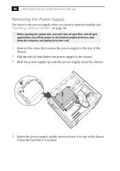
... the power supply up until the power supply clears the chassis. A 4 Rotate the power supply upside down the computer, and unplug the power cord. 1 Remove the screw that secures the power supply to the rear of the chassis. 2 Pull the tab (A) that latches the power supply to all attached peripheral devices, shut down and rest it on page 34). ! 44 VAIO Digital Studio...
... the power supply up until the power supply clears the chassis. A 4 Rotate the power supply upside down the computer, and unplug the power cord. 1 Remove the screw that secures the power supply to the rear of the chassis. 2 Pull the tab (A) that latches the power supply to all attached peripheral devices, shut down and rest it on page 34). ! 44 VAIO Digital Studio...

System Reference Manual
Page 59
Upgrading and Maintaining Components 45 Replacing the Power Supply 1 Rotate the power supply down and slide it down along the rails on each side of the chassis opening. 2 Replace the screw that secures the power supply to the rear of the chassis.
Upgrading and Maintaining Components 45 Replacing the Power Supply 1 Rotate the power supply down and slide it down along the rails on each side of the chassis opening. 2 Replace the screw that secures the power supply to the rear of the chassis.
System Reference Manual
Page 61
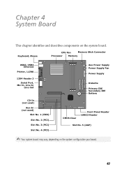
... In Line Out CD-In (not used) Aux-In (not used) Slot No. 1 (CNR) Slot No. 2 (PCI) Slot No. 3 (PCI) Slot No. 4 (PCI) Aux Power Supply Power Supply Fan Power Supply Diskette Primary IDE Secondary IDE Battery CMOS Clear Front Panel Header USB23 Header Slot No. 5 (AGP) ✍ Your system board may vary, depending on the...
... In Line Out CD-In (not used) Aux-In (not used) Slot No. 1 (CNR) Slot No. 2 (PCI) Slot No. 3 (PCI) Slot No. 4 (PCI) Aux Power Supply Power Supply Fan Power Supply Diskette Primary IDE Secondary IDE Battery CMOS Clear Front Panel Header USB23 Header Slot No. 5 (AGP) ✍ Your system board may vary, depending on the...
System Reference Manual
Page 63
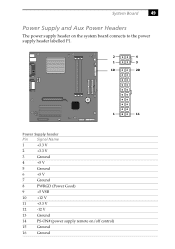
System Board 49 Power Supply and Aux Power Headers The power supply header on the system board connects to the power supply header labelled P1. 2 4 1 3 10 20 1 11 Power Supply header Pin Signal Name 1 +3.3 V 2 +3.3 V 3 Ground 4 +5 V 5 Ground 6 +5 V 7 Ground 8 PWRGD (Power Good) 9 +5 VSB 10 +12 V 11 +3.3 V 12 -12 V 13 Ground 14 PS-ON# (power supply remote on/off control) 15 Ground 16 Ground
System Board 49 Power Supply and Aux Power Headers The power supply header on the system board connects to the power supply header labelled P1. 2 4 1 3 10 20 1 11 Power Supply header Pin Signal Name 1 +3.3 V 2 +3.3 V 3 Ground 4 +5 V 5 Ground 6 +5 V 7 Ground 8 PWRGD (Power Good) 9 +5 VSB 10 +12 V 11 +3.3 V 12 -12 V 13 Ground 14 PS-ON# (power supply remote on/off control) 15 Ground 16 Ground


