
Quick Start Guide
Page 51
...may occur during a brief period of the power supply to your computer, components, and accessories. This will not be using the computer for ten minutes. Notes on Use Notes on Use The information in the power supply. AC derived from the wall outlet or power strip. ❑ Do not place heavy objects..., refer the repair or replacement of power loss. ❑ The power control button on the front panel does not turn off the system AC power. To remove power from the system, you must turn off the computer and then unplug the AC power cord from different supply lines may result in an...
...may occur during a brief period of the power supply to your computer, components, and accessories. This will not be using the computer for ten minutes. Notes on Use Notes on Use The information in the power supply. AC derived from the wall outlet or power strip. ❑ Do not place heavy objects..., refer the repair or replacement of power loss. ❑ The power control button on the front panel does not turn off the system AC power. To remove power from the system, you must turn off the computer and then unplug the AC power cord from different supply lines may result in an...

System Reference Manual
Page 10
...VAIO Digital Studio System Reference Manual Chapter 3 - Miscellaneous Technical Information ......... 63 User and Supervisor Passwords 64 Beep Code Error Messages 65 PCI Configuration Status and Error Messages 66 DMA Channel Assignments 68 System I /O Slot 38 Installing a 3.5-inch Internal Hard Disk Drive 39 To identify additional hard disk space 43 Removing the Power Supply... 44 Replacing the Power Supply 45 Chapter 4 - Removing, Installing, and Replacing Components 23 Removing the Side Cover 24 Replacing the Side Cover 25 Removing a ...
...VAIO Digital Studio System Reference Manual Chapter 3 - Miscellaneous Technical Information ......... 63 User and Supervisor Passwords 64 Beep Code Error Messages 65 PCI Configuration Status and Error Messages 66 DMA Channel Assignments 68 System I /O Slot 38 Installing a 3.5-inch Internal Hard Disk Drive 39 To identify additional hard disk space 43 Removing the Power Supply... 44 Replacing the Power Supply 45 Chapter 4 - Removing, Installing, and Replacing Components 23 Removing the Side Cover 24 Replacing the Side Cover 25 Removing a ...

System Reference Manual
Page 39
...see "Covering an Open I/O Slot" on page 38). 6 Replace the side cover (see "Replacing the Side Cover" on page 25). As a precaution, touch any exposed metal part on the metal chassis (preferably the metal part on the power supply) before handling an add-in card to discharge any static electricity ...in your body. 5 If you do not touch any components or contacts on the card. Removing, Installing, and Replacing Components 27 ! Static electricity in your body may...
...see "Covering an Open I/O Slot" on page 38). 6 Replace the side cover (see "Replacing the Side Cover" on page 25). As a precaution, touch any exposed metal part on the metal chassis (preferably the metal part on the power supply) before handling an add-in card to discharge any static electricity ...in your body. 5 If you do not touch any components or contacts on the card. Removing, Installing, and Replacing Components 27 ! Static electricity in your body may...

System Reference Manual
Page 45
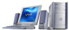
...module to eject the module from its socket. ! The computer may need to remove a memory module if you wish to remove. ✍ The memory modules are located beneath the power supply. 4 Push down the computer, and unplug the power cord. 1 Remove the side cover (see "Removing the... Side Cover" on page 24). 2 Remove the power supply (see "Removing the Power Supply" on page 44). 3 Locate the memory module you change the memory configuration or replace a bad module....
...module to eject the module from its socket. ! The computer may need to remove a memory module if you wish to remove. ✍ The memory modules are located beneath the power supply. 4 Push down the computer, and unplug the power cord. 1 Remove the side cover (see "Removing the... Side Cover" on page 24). 2 Remove the power supply (see "Removing the Power Supply" on page 44). 3 Locate the memory module you change the memory configuration or replace a bad module....

System Reference Manual
Page 46
.... ✍ Use only PC2100 memory. 34 VAIO Digital Studio System Reference Manual Installing System Memory ! Memory module configurations (MB)* DIMM1 128, 256, 512 DIMM2 128, 256, 512 * Your computer ships with more than 512 MB DDR-SDRAM depending on the configuration you wish to replace (see "Removing the Power Supply" on page 44). 6 Remove the...
.... ✍ Use only PC2100 memory. 34 VAIO Digital Studio System Reference Manual Installing System Memory ! Memory module configurations (MB)* DIMM1 128, 256, 512 DIMM2 128, 256, 512 * Your computer ships with more than 512 MB DDR-SDRAM depending on the configuration you wish to replace (see "Removing the Power Supply" on page 44). 6 Remove the...

System Reference Manual
Page 47
Hold the add-in card. ✍ Grasp the card with one hand on each end, and gently pull up as you rock the card from side to discharge any static electricity in your body. Removing, Installing, and Replacing Components 35 8 Remove the AGP add-in card by its edges and do not touch any components or contacts on the card. As a precaution, touch any exposed metal part on the metal chassis (preferably the metal part on the card. Static electricity in your body may damage sensitive components on the power supply) before handling an add-in card to side. !
Hold the add-in card. ✍ Grasp the card with one hand on each end, and gently pull up as you rock the card from side to discharge any static electricity in your body. Removing, Installing, and Replacing Components 35 8 Remove the AGP add-in card by its edges and do not touch any components or contacts on the card. As a precaution, touch any exposed metal part on the metal chassis (preferably the metal part on the card. Static electricity in your body may damage sensitive components on the power supply) before handling an add-in card to side. !
System Reference Manual
Page 48
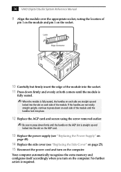
... card. 13 Replace the power supply (see "Replacing the Power Supply" on page 45). 14 Replace the side cover (see "Replacing the Side Cover" on page 25). 15 Reconnect the power cord and turn on the socket. Your computer automatically recognizes the extra memory and configures itself accordingly when you turn on each side of the module. 36 VAIO Digital Studio...
... card. 13 Replace the power supply (see "Replacing the Power Supply" on page 45). 14 Replace the side cover (see "Replacing the Side Cover" on page 25). 15 Reconnect the power cord and turn on the socket. Your computer automatically recognizes the extra memory and configures itself accordingly when you turn on each side of the module. 36 VAIO Digital Studio...

System Reference Manual
Page 57
Removing, Installing, and Replacing Components 45 Replacing the Power Supply 1 Rotate the power supply down and slide it down along the rails on each side of the chassis opening. 2 Replace the screw that secures the power supply to the rear of the chassis.
Removing, Installing, and Replacing Components 45 Replacing the Power Supply 1 Rotate the power supply down and slide it down along the rails on each side of the chassis opening. 2 Replace the screw that secures the power supply to the rear of the chassis.

Online Help Center (VAIO User Guide)
Page 55
... power supply. The battery backup safeguards your equipment, refer the repair or replacement of power loss. The power control button on the front panel does not turn off and let it out by power surges. This will not be hot. Do not attempt to qualified personnel only. The surge protector prevents damage to your computer...
... power supply. The battery backup safeguards your equipment, refer the repair or replacement of power loss. The power control button on the front panel does not turn off and let it out by power surges. This will not be hot. Do not attempt to qualified personnel only. The surge protector prevents damage to your computer...

Online Help Center (VAIO User Guide)
Page 82
... the screw that secures the power supply to remove. 6. See Removing the side cover. 4. Locate the DIMM you upgrade your local retailer. Push down your computer and turn off all peripheral devices, such as your printer. 2. For memory replacement or upgrades, use only 2.5V... proper safety precautions when you purchased. Unplug your Sony computer. See the Specifications sheet for details about the amount of the module to access the DIMM slots. 5. Unplug your computer. Store the module in your computer and any peripheral devices. 3. Gently place the unit...
... the screw that secures the power supply to remove. 6. See Removing the side cover. 4. Locate the DIMM you upgrade your local retailer. Push down your computer and turn off all peripheral devices, such as your printer. 2. For memory replacement or upgrades, use only 2.5V... proper safety precautions when you purchased. Unplug your Sony computer. See the Specifications sheet for details about the amount of the module to access the DIMM slots. 5. Unplug your computer. Store the module in your computer and any peripheral devices. 3. Gently place the unit...

Online Help Center (VAIO User Guide)
Page 83
... to its original position and slide it on top of the DIMM into place. 8. See Replacing the side cover. Reinstall the power supply by the edges, and remove it clears the chassis. Rotate the power supply to relieve pressure. Replace the side cover. The end latches snap into the chassis until the it from the...
... to its original position and slide it on top of the DIMM into place. 8. See Replacing the side cover. Reinstall the power supply by the edges, and remove it clears the chassis. Rotate the power supply to relieve pressure. Replace the side cover. The end latches snap into the chassis until the it from the...
Online Help Center (VAIO User Guide)
Page 86
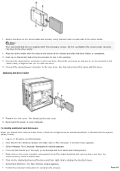
...Disk label identified with pin 1 of the drive holder. Push up on the Unallocated area of the ribbon cable, is supplied with the drive. Connect the second power connector to display the shortcut menu. 7. See the instructions that pin 1, on the red side of the drive and ... Connect the second drive connector to complete the process. Replacing the drive holder 13. Reconnect the power to the drive holder. 9. The New Partition wizard appears. 8. 8. Align the drive holder with screws, using the two holes on My Computer. Replace the side cover. Page 86 Do not overtighten the ...
...Disk label identified with pin 1 of the drive holder. Push up on the Unallocated area of the ribbon cable, is supplied with the drive. Connect the second power connector to display the shortcut menu. 7. See the instructions that pin 1, on the red side of the drive and ... Connect the second drive connector to complete the process. Replacing the drive holder 13. Reconnect the power to the drive holder. 9. The New Partition wizard appears. 8. 8. Align the drive holder with screws, using the two holes on My Computer. Replace the side cover. Page 86 Do not overtighten the ...

VAIO User Guide (primary manual)
Page 83
... to your computer from the wall outlet if you must turn the system off and let it out by power surges. This device prevents damage to purchase an Uninterruptible Power Supply (UPS). Never pull the cord itself. ❑ Unplug your equipment, refer the repair or replacement of connection.... ❑ Do not share the AC outlet with any other power-consuming equipment, such ...
... to your computer from the wall outlet if you must turn the system off and let it out by power surges. This device prevents damage to purchase an Uninterruptible Power Supply (UPS). Never pull the cord itself. ❑ Unplug your equipment, refer the repair or replacement of connection.... ❑ Do not share the AC outlet with any other power-consuming equipment, such ...


