
Quick Start Guide
Page 37
...the manual that came with your computer. I want to solve common problems you plugged the computer into a power strip or Uninterruptible Power Supply (UPS), make sure the power strip or UPS is turned on and working. ❑ Check that the monitor is plugged into a power source and that it is turned ...the VAIO Help and Support menu, click VAIO User Guide. 35 Check that the power light is lit on . Check that the computer is plugged into a power source and turned on the front panel of the computer. ❑ Confirm that a disk is not in the floppy disk drive (unless you call Sony ...
...the manual that came with your computer. I want to solve common problems you plugged the computer into a power strip or Uninterruptible Power Supply (UPS), make sure the power strip or UPS is turned on and working. ❑ Check that the monitor is plugged into a power source and that it is turned ...the VAIO Help and Support menu, click VAIO User Guide. 35 Check that the power light is lit on . Check that the computer is plugged into a power source and turned on the front panel of the computer. ❑ Confirm that a disk is not in the floppy disk drive (unless you call Sony ...

Quick Start Guide
Page 51
..., pull it cool for your computer, components, and accessories. Never pull the cord itself. ❑ Unplug your computer caused by the plug. To avoid personal injury or damage to your equipment, refer the repair or replacement of the power supply to your computer from the wall outlet if you... live in an area that the processor heat sink will ensure that experiences frequent power fluctuations, you must turn off the computer and then unplug the AC power cord from different supply lines may result in ...
..., pull it cool for your computer, components, and accessories. Never pull the cord itself. ❑ Unplug your computer caused by the plug. To avoid personal injury or damage to your equipment, refer the repair or replacement of the power supply to your computer from the wall outlet if you... live in an area that the processor heat sink will ensure that experiences frequent power fluctuations, you must turn off the computer and then unplug the AC power cord from different supply lines may result in ...
Quick Start Guide
Page 62
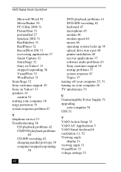
...31 recovering applications 37 Smart Capture 32 SonicStage 32 Sony on Yahoo! 33 stopped responding 38 VisualFlow 33 WordPerfect 33 SonicStage 32 Sony customer support 19 Sony on Yahoo! 33 speakers 14 caution 52 starting your computer 18 surge protectors 51 system response problem 47 ... audio problems 43 Sony customer support 19 startup problems 37 system response 47 Topics 37 turning off your computer 25, 51 turning on your computer 18 TV interference 53 U Uninterruptible Power Supply 51 upgrading your computer 54 UPS 51 V VAIO Action Setup 33 VAIO AV Applications 5 VAIO Smart keyboard 6 ...
...31 recovering applications 37 Smart Capture 32 SonicStage 32 Sony on Yahoo! 33 stopped responding 38 VisualFlow 33 WordPerfect 33 SonicStage 32 Sony customer support 19 Sony on Yahoo! 33 speakers 14 caution 52 starting your computer 18 surge protectors 51 system response problem 47 ... audio problems 43 Sony customer support 19 startup problems 37 system response 47 Topics 37 turning off your computer 25, 51 turning on your computer 18 TV interference 53 U Uninterruptible Power Supply 51 upgrading your computer 54 UPS 51 V VAIO Action Setup 33 VAIO AV Applications 5 VAIO Smart keyboard 6 ...

System Reference Manual
Page 10
CMOS Setup Options 53 Main Screen 55 Advanced Screen 57 Power Screen 59 Boot Screen 60 Exit Screen 61 Chapter 6 - x VAIO Digital Studio System Reference Manual Chapter 3 - Removing, Installing, and Replacing Components 23 Removing the Side Cover 24 Replacing the Side Cover ... 37 Covering an Open I /O Address Map 69 Memory Map 71 IRQ Settings 72 System Board 47 Memory Module (DDR-DIMM) Slots 48 Power Supply and Aux Power Headers 49 CLR CMOS Jumper 51 Chapter 5 - Miscellaneous Technical Information ......... 63 User and Supervisor Passwords 64 Beep Code Error Messages 65 PCI...
CMOS Setup Options 53 Main Screen 55 Advanced Screen 57 Power Screen 59 Boot Screen 60 Exit Screen 61 Chapter 6 - x VAIO Digital Studio System Reference Manual Chapter 3 - Removing, Installing, and Replacing Components 23 Removing the Side Cover 24 Replacing the Side Cover ... 37 Covering an Open I /O Address Map 69 Memory Map 71 IRQ Settings 72 System Board 47 Memory Module (DDR-DIMM) Slots 48 Power Supply and Aux Power Headers 49 CLR CMOS Jumper 51 Chapter 5 - Miscellaneous Technical Information ......... 63 User and Supervisor Passwords 64 Beep Code Error Messages 65 PCI...

System Reference Manual
Page 33
For more information about configuring a UPS device, refer to select and configure an Uninterruptible Power Supply (UPS) device for your system. ✍ A UPS device is an optional accessory not currently supplied with your system. 9 Select and configure the settings most appropriate for your Microsoft® Windows® XP operating system Help. Configuring Your System 21 8 Click the UPS tab. The UPS tab enables you to your system and click OK.
For more information about configuring a UPS device, refer to select and configure an Uninterruptible Power Supply (UPS) device for your system. ✍ A UPS device is an optional accessory not currently supplied with your system. 9 Select and configure the settings most appropriate for your Microsoft® Windows® XP operating system Help. Configuring Your System 21 8 Click the UPS tab. The UPS tab enables you to your system and click OK.

System Reference Manual
Page 36
24 VAIO Digital Studio System Reference Manual Removing the Side Cover You must remove the side cover to access the system board, add-in cards, power supply, battery, memory, and internal drives. 1 From the rear of the unit, pull the metal tab shown in the next diagram. 2 Pull the top of the cover away from the unit about two inches, then gently lift out the cover.
24 VAIO Digital Studio System Reference Manual Removing the Side Cover You must remove the side cover to access the system board, add-in cards, power supply, battery, memory, and internal drives. 1 From the rear of the unit, pull the metal tab shown in the next diagram. 2 Pull the top of the cover away from the unit about two inches, then gently lift out the cover.

System Reference Manual
Page 39
... body may damage sensitive components on the card. As a precaution, touch any exposed metal part on the metal chassis (preferably the metal part on the power supply) before handling an add-in card to discharge any components or contacts on the card. Removing, Installing, and Replacing Components 27 !
... body may damage sensitive components on the card. As a precaution, touch any exposed metal part on the metal chassis (preferably the metal part on the power supply) before handling an add-in card to discharge any components or contacts on the card. Removing, Installing, and Replacing Components 27 !

System Reference Manual
Page 45
...close all open files, exit all open applications, turn off the power to all sockets filled. ! The computer may need to remove a memory module if you wish to remove. ✍ The memory modules are located beneath the power supply. 4 Push down the handle on page 44). 3 Locate the... Module You may ship with all attached peripheral devices, shut down the computer, and unplug the power cord. 1 Remove the side cover (see "Removing the Side Cover" on page 24). 2 Remove the power supply (see "Removing the Power Supply" on each side of the memory module to discharge static electricity in ...
...close all open files, exit all open applications, turn off the power to all sockets filled. ! The computer may need to remove a memory module if you wish to remove. ✍ The memory modules are located beneath the power supply. 4 Push down the handle on page 44). 3 Locate the... Module You may ship with all attached peripheral devices, shut down the computer, and unplug the power cord. 1 Remove the side cover (see "Removing the Side Cover" on page 24). 2 Remove the power supply (see "Removing the Power Supply" on each side of the memory module to discharge static electricity in ...

System Reference Manual
Page 46
...add-in card to the chassis. 7 Press down the computer, and unplug the power cord. 1 Choose the size of the memory modules. DDR-SDRAM is expandable to replace (see "Removing the Power Supply" on page 37). ! 34 VAIO Digital Studio System Reference Manual Installing System Memory ! Before ...opening the system unit, save and close all open files, exit all open applications, turn off the power to all attached peripheral devices, shut ...
...add-in card to the chassis. 7 Press down the computer, and unplug the power cord. 1 Choose the size of the memory modules. DDR-SDRAM is expandable to replace (see "Removing the Power Supply" on page 37). ! 34 VAIO Digital Studio System Reference Manual Installing System Memory ! Before ...opening the system unit, save and close all open files, exit all open applications, turn off the power to all attached peripheral devices, shut ...

System Reference Manual
Page 47
Hold the add-in your body. Static electricity in card by its edges and do not touch any static electricity in card. ✍ Grasp the card with one hand on each end, and gently pull up as you rock the card from side to discharge any components or contacts on the card. As a precaution, touch any exposed metal part on the metal chassis (preferably the metal part on the power supply) before handling an add-in card to side. ! Removing, Installing, and Replacing Components 35 8 Remove the AGP add-in your body may damage sensitive components on the card.
Hold the add-in your body. Static electricity in card by its edges and do not touch any static electricity in card. ✍ Grasp the card with one hand on each end, and gently pull up as you rock the card from side to discharge any components or contacts on the card. As a precaution, touch any exposed metal part on the metal chassis (preferably the metal part on the power supply) before handling an add-in card to side. ! Removing, Installing, and Replacing Components 35 8 Remove the AGP add-in your body may damage sensitive components on the card.
System Reference Manual
Page 48
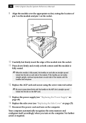
If the handles are straight up and locked into the slot on the computer. No further action is straight up and locked into the slot on the AGP card. 13 Replace the power supply (see "Replacing the Power Supply" on page 45). 14 Replace the side cover (see "Replacing the Side Cover" on page 25). 15... of the module into the socket. 11 Press down firmly and evenly at both corners until the handle on the AGP slot is required. 36 VAIO Digital Studio System Reference Manual 9 Align the module over the appropriate socket, noting the location of pin 1 on the module and pin 1 on the...
If the handles are straight up and locked into the slot on the computer. No further action is straight up and locked into the slot on the AGP card. 13 Replace the power supply (see "Replacing the Power Supply" on page 45). 14 Replace the side cover (see "Replacing the Side Cover" on page 25). 15... of the module into the socket. 11 Press down firmly and evenly at both corners until the handle on the AGP slot is required. 36 VAIO Digital Studio System Reference Manual 9 Align the module over the appropriate socket, noting the location of pin 1 on the module and pin 1 on the...

System Reference Manual
Page 52
A B C Drive connector Power supply connector Tab Disk drive holder 4 Disconnect the power connector (B in diagram). 40 VAIO Digital Studio System Reference Manual 3 Disconnect the drive connector (A in diagram). 5 Pull out on the tab (C) that secures the drive holder to the chassis.
A B C Drive connector Power supply connector Tab Disk drive holder 4 Disconnect the power connector (B in diagram). 40 VAIO Digital Studio System Reference Manual 3 Disconnect the drive connector (A in diagram). 5 Pull out on the tab (C) that secures the drive holder to the chassis.

System Reference Manual
Page 56
... power supply upside down the computer, and unplug the power cord. 1 Remove the screw that latches the power supply to the chassis. 3 Slide the power supply up until the power supply clears the chassis. Before opening the system unit, save and close all open files, exit all open applications, turn off the power... to all attached peripheral devices, shut down and rest it on page 34). ! 44 VAIO Digital Studio System Reference Manual Removing the Power Supply You remove the power supply when you insert a memory module (see "Installing ...
... power supply upside down the computer, and unplug the power cord. 1 Remove the screw that latches the power supply to the chassis. 3 Slide the power supply up until the power supply clears the chassis. Before opening the system unit, save and close all open files, exit all open applications, turn off the power... to all attached peripheral devices, shut down and rest it on page 34). ! 44 VAIO Digital Studio System Reference Manual Removing the Power Supply You remove the power supply when you insert a memory module (see "Installing ...

System Reference Manual
Page 57
Removing, Installing, and Replacing Components 45 Replacing the Power Supply 1 Rotate the power supply down and slide it down along the rails on each side of the chassis opening. 2 Replace the screw that secures the power supply to the rear of the chassis.
Removing, Installing, and Replacing Components 45 Replacing the Power Supply 1 Rotate the power supply down and slide it down along the rails on each side of the chassis opening. 2 Replace the screw that secures the power supply to the rear of the chassis.

System Reference Manual
Page 59
... Processor Memory USB3, USB4, Ethernet Printer, i.LINK 1394 Header 2 Serial Port, Mic In, Line In, Line Out 1394 Header 3 Video (not used) Aux-in Power Supply Fan Aux Power Supply Power Supply Secondary IDE Primary IDE Diskette Battery CMOS Clear CD-In (not used) Slot No. 3 (PCI) Slot No. 2 (PCI) Slot No. 1 (PCI) Front Panel Header...
... Processor Memory USB3, USB4, Ethernet Printer, i.LINK 1394 Header 2 Serial Port, Mic In, Line In, Line Out 1394 Header 3 Video (not used) Aux-in Power Supply Fan Aux Power Supply Power Supply Secondary IDE Primary IDE Diskette Battery CMOS Clear CD-In (not used) Slot No. 3 (PCI) Slot No. 2 (PCI) Slot No. 1 (PCI) Front Panel Header...

System Reference Manual
Page 61
System Board 49 Power Supply and Aux Power Headers The power supply header on the system board connects to the power supply header labelled P1. 2 4 1 3 10 20 1 11 Power Supply header Pin Signal Name 1 +3.3 V 2 +3.3 V 3 Ground 4 +5 V 5 Ground 6 +5 V 7 Ground 8 PWRGD (Power Good) 9 +5 VSB 10 +12 V 11 +3.3 V 12 -12 V 13 Ground 14 PS-ON# (power supply remote on/off control) 15 Ground 16 Ground
System Board 49 Power Supply and Aux Power Headers The power supply header on the system board connects to the power supply header labelled P1. 2 4 1 3 10 20 1 11 Power Supply header Pin Signal Name 1 +3.3 V 2 +3.3 V 3 Ground 4 +5 V 5 Ground 6 +5 V 7 Ground 8 PWRGD (Power Good) 9 +5 VSB 10 +12 V 11 +3.3 V 12 -12 V 13 Ground 14 PS-ON# (power supply remote on/off control) 15 Ground 16 Ground

System Reference Manual
Page 62
50 VAIO Digital Studio System Reference Manual Power Supply header (Continued) Pin Signal Name 17 Ground 18 No Connection 19 +5 V 20 +5 V Aux Power header Pin Signal Name 1 Ground 2 Ground 3 +12 V 4 +12 V
50 VAIO Digital Studio System Reference Manual Power Supply header (Continued) Pin Signal Name 17 Ground 18 No Connection 19 +5 V 20 +5 V Aux Power header Pin Signal Name 1 Ground 2 Ground 3 +12 V 4 +12 V

Online Help Center (VAIO User Guide)
Page 36
...a product contains an IEEE1394 connection. Caution: The total power supplied by calling 1-888-315-7669 (toll free). Page 36 i.LINK (IEEE1394) Compatibility Your VAIO computer may include either 4-pin or 6-pin, or both types, of Sony used only to 12V. The i.LINK connection may not... of i.LINK ports. Before connecting compatible i.LINK PC peripherals to a connected device. Sony computer supplies, accessories, and peripherals can : supply power from the Sony VAIO Direct Web site at http://vaio.sonystyle.com, or by the 6-pin i.LINK port cannot exceed 6 watts. All products...
...a product contains an IEEE1394 connection. Caution: The total power supplied by calling 1-888-315-7669 (toll free). Page 36 i.LINK (IEEE1394) Compatibility Your VAIO computer may include either 4-pin or 6-pin, or both types, of Sony used only to 12V. The i.LINK connection may not... of i.LINK ports. Before connecting compatible i.LINK PC peripherals to a connected device. Sony computer supplies, accessories, and peripherals can : supply power from the Sony VAIO Direct Web site at http://vaio.sonystyle.com, or by the 6-pin i.LINK port cannot exceed 6 watts. All products...

Online Help Center (VAIO User Guide)
Page 47
...If the software application continues to ECP, EPP, or bi- The VAIO Help and Support dialog box appears. 2. directional? I change the parallel port type using a bootable floppy disk). Confirm that the power cord and all cables are connected firmly. If you can ... "Not responding." 3. For troubleshooting information, you plugged the computer into a power strip or Uninterruptible Power Supply (UPS), make sure the power strip or UPS is turned on . Select the application that the monitor is plugged into a power source and turned on and working. Check that ...
...If the software application continues to ECP, EPP, or bi- The VAIO Help and Support dialog box appears. 2. directional? I change the parallel port type using a bootable floppy disk). Confirm that the power cord and all cables are connected firmly. If you can ... "Not responding." 3. For troubleshooting information, you plugged the computer into a power strip or Uninterruptible Power Supply (UPS), make sure the power strip or UPS is turned on . Select the application that the monitor is plugged into a power source and turned on and working. Check that ...

Online Help Center (VAIO User Guide)
Page 55
...; If you will not be using the computer for your computer from different supply lines may want to qualified personnel only. The power source Your computer operates on the front panel does not turn off the system AC power. Page 55 The surge protector prevents damage to open the power supply. This will ensure that the processor...
...; If you will not be using the computer for your computer from different supply lines may want to qualified personnel only. The power source Your computer operates on the front panel does not turn off the system AC power. Page 55 The surge protector prevents damage to open the power supply. This will ensure that the processor...


