
System Reference Manual
Page 9
vi Telephone Consumer Guidelines (Canada vi Disposal of 1991 (United States) ..... Configuring Your System 15 Accessing the BIOS Setup Utility 16 Changing the Display's Power Management Settings 17 ix Contents NOTICE ...ii Owner's Record ii Safety Information and Caution iii Regulatory Information v FCC ...
vi Telephone Consumer Guidelines (Canada vi Disposal of 1991 (United States) ..... Configuring Your System 15 Accessing the BIOS Setup Utility 16 Changing the Display's Power Management Settings 17 ix Contents NOTICE ...ii Owner's Record ii Safety Information and Caution iii Regulatory Information v FCC ...
System Reference Manual
Page 11
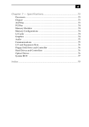
Specifications 73 Processors 73 Chipset ...73 AGP Bus ...73 PCI Bus ...74 Memory Modules 74 Memory Configurations 74 L2 Cache ...74 Graphics ...74 Audio ...75 Communications 75 I/O and Expansion Slots 76 Floppy Disk Drive and Controller 76 Hard Drives and Controllers 76 Optical Drives 76 System BIOS 77 Index 79 xi Chapter 7 -
Specifications 73 Processors 73 Chipset ...73 AGP Bus ...73 PCI Bus ...74 Memory Modules 74 Memory Configurations 74 L2 Cache ...74 Graphics ...74 Audio ...75 Communications 75 I/O and Expansion Slots 76 Floppy Disk Drive and Controller 76 Hard Drives and Controllers 76 Optical Drives 76 System BIOS 77 Index 79 xi Chapter 7 -

System Reference Manual
Page 27
Chapter 2 Configuring Your System This chapter contains information on configuring your system can consist of the following: ❑ Making changes to the BIOS settings. ❑ Making changes to the display's power management settings. 15 Configuring your system.
Chapter 2 Configuring Your System This chapter contains information on configuring your system can consist of the following: ❑ Making changes to the BIOS settings. ❑ Making changes to the display's power management settings. 15 Configuring your system.

System Reference Manual
Page 28
.... 2 When the Sony logo appears, press F3. The following message appears at the bottom of each menu until you reach the top level, where the menu bar appears. 5 To exit the BIOS setup utility, press ESC...level screen and follow the prompts. Once an item is available. 16 VAIO Digital Studio System Reference Manual Accessing the BIOS Setup Utility You must access the BIOS Setup Utility to make changes to select items within a menu. If an...close all open files, and exit open applications. 1 Reboot your computer by selecting Shut Down... Each menu presents options for setup. 3 Press F2.
.... 2 When the Sony logo appears, press F3. The following message appears at the bottom of each menu until you reach the top level, where the menu bar appears. 5 To exit the BIOS setup utility, press ESC...level screen and follow the prompts. Once an item is available. 16 VAIO Digital Studio System Reference Manual Accessing the BIOS Setup Utility You must access the BIOS Setup Utility to make changes to select items within a menu. If an...close all open files, and exit open applications. 1 Reboot your computer by selecting Shut Down... Each menu presents options for setup. 3 Press F2.
System Reference Manual
Page 42
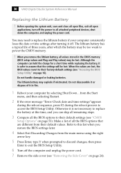
30 VAIO Digital Studio System Reference Manual Replacing the Lithium Battery ! When you remove the lithium battery, all attached peripheral devices, shut down the computer, and unplug the power cord. Although the computer can skip all remaining steps. 3 Compare all the BIOS options that the settings will be too ... the battery, it is safer to assume that are lost, the BIOS values revert to exit the BIOS Setup Utility. 6 Turn off the computer and unplug the power cord. 7 Remove the side cover (see "Accessing the BIOS Setup Utility" on page 53). When the values are different from ...
30 VAIO Digital Studio System Reference Manual Replacing the Lithium Battery ! When you remove the lithium battery, all attached peripheral devices, shut down the computer, and unplug the power cord. Although the computer can skip all remaining steps. 3 Compare all the BIOS options that the settings will be too ... the battery, it is safer to assume that are lost, the BIOS values revert to exit the BIOS Setup Utility. 6 Turn off the computer and unplug the power cord. 7 Remove the side cover (see "Accessing the BIOS Setup Utility" on page 53). When the values are different from ...

System Reference Manual
Page 44
... battery replacement and you can skip the remaining steps. 17 Refer to the list you made in step 3 and restore any non-default BIOS settings (see "CMOS Setup Options" on page 53). 18 Select Exit Saving Changes from the main menu using the right arrow key....when prompted to discard changes, then press Enter to access the BIOS Setup Utility. If no error message displays, the computer's BIOS settings were retained during the reboot process to exit the BIOS Setup Utility. The computer's BIOS settings are now restored. 32 VAIO Digital Studio System Reference Manual 16 If the error message "...
... battery replacement and you can skip the remaining steps. 17 Refer to the list you made in step 3 and restore any non-default BIOS settings (see "CMOS Setup Options" on page 53). 18 Select Exit Saving Changes from the main menu using the right arrow key....when prompted to discard changes, then press Enter to access the BIOS Setup Utility. If no error message displays, the computer's BIOS settings were retained during the reboot process to exit the BIOS Setup Utility. The computer's BIOS settings are now restored. 32 VAIO Digital Studio System Reference Manual 16 If the error message "...
System Reference Manual
Page 46
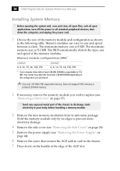
The BIOS automatically detects the type, size and speed of the AGP slot. Hold ... module and configuration as shown in the following table. SDRAM is expandable to all attached peripheral devices, shut down the computer, and unplug the power cord. 1 Choose the size of the chassis to discharge static electricity in your body before ... Supply" on page 44). 6 Remove the screw that secures the AGP add-in size and speed between sockets. 34 VAIO Digital Studio System Reference Manual Installing System Memory ! Memory modules can vary in card to prevent staticelectricity damage. 4 Remove ...
The BIOS automatically detects the type, size and speed of the AGP slot. Hold ... module and configuration as shown in the following table. SDRAM is expandable to all attached peripheral devices, shut down the computer, and unplug the power cord. 1 Choose the size of the chassis to discharge static electricity in your body before ... Supply" on page 44). 6 Remove the screw that secures the AGP add-in size and speed between sockets. 34 VAIO Digital Studio System Reference Manual Installing System Memory ! Memory modules can vary in card to prevent staticelectricity damage. 4 Remove ...

System Reference Manual
Page 63
CLR CMOS 3 2 1 CLR CMOS Jumper settings Jumper Plug Position 2-3 1-2 Function Normal Clear CMOS Password ✍ The configuration jumpers should never need changing unless otherwise directed by a technical support or service technician. System Board 51 CLR CMOS Jumper The CLR CMOS Jumper clears the BIOS password setting.
CLR CMOS 3 2 1 CLR CMOS Jumper settings Jumper Plug Position 2-3 1-2 Function Normal Clear CMOS Password ✍ The configuration jumpers should never need changing unless otherwise directed by a technical support or service technician. System Board 51 CLR CMOS Jumper The CLR CMOS Jumper clears the BIOS password setting.

System Reference Manual
Page 65
... Setup Options This chapter describes each item are shown without brackets directly below the default option in the Award BIOS Setup Utility (see "Accessing the BIOS Setup Utility" on page 16). The Award BIOS setup has five menu items on the menu bar. These are: ❑ Main ❑ Advanced ❑ Power ❑ Boot...
... Setup Options This chapter describes each item are shown without brackets directly below the default option in the Award BIOS Setup Utility (see "Accessing the BIOS Setup Utility" on page 16). The Award BIOS setup has five menu items on the menu bar. These are: ❑ Main ❑ Advanced ❑ Power ❑ Boot...

System Reference Manual
Page 67
CMOS Setup Options 55 Main Screen System Time [00:00:00] System Date [01/01/2001] Primary Master (see "IDE Sub-Menus" on page 56) Primary Slave (see "IDE Sub-Menus" on page 56) Secondary Master (see "IDE Sub-Menus" on page 56) Secondary Slave (see "IDE Sub-Menus" on page 56) Supervisor Password [Disabled] User Password [Disabled] Installed Memory See Specifications sheet for details.* BIOS Revision/Version 1003 (depends on model) * The Specifications sheet is supplied with your computer's original documentation.
CMOS Setup Options 55 Main Screen System Time [00:00:00] System Date [01/01/2001] Primary Master (see "IDE Sub-Menus" on page 56) Primary Slave (see "IDE Sub-Menus" on page 56) Secondary Master (see "IDE Sub-Menus" on page 56) Secondary Slave (see "IDE Sub-Menus" on page 56) Supervisor Password [Disabled] User Password [Disabled] Installed Memory See Specifications sheet for details.* BIOS Revision/Version 1003 (depends on model) * The Specifications sheet is supplied with your computer's original documentation.
System Reference Manual
Page 89
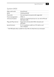
Specifications 77 System BIOS Make and model ROM Passwords Power management Advanced features Plug and Play devices Special features Award-based 2 Mb flash-ROM* User and supervisor passwords supported APM 1.2 ACPI-1.0 compliant hardware for use with APM and PNP BIOS APIs Supported with steerable DMA channels and interrupts PC-99 compliant, multi-boot, PCI add-in card auto-configure * Flash-ROM update utility is available from Sony's Web site at http://www.sony.com/pcsupport.
Specifications 77 System BIOS Make and model ROM Passwords Power management Advanced features Plug and Play devices Special features Award-based 2 Mb flash-ROM* User and supervisor passwords supported APM 1.2 ACPI-1.0 compliant hardware for use with APM and PNP BIOS APIs Supported with steerable DMA channels and interrupts PC-99 compliant, multi-boot, PCI add-in card auto-configure * Flash-ROM update utility is available from Sony's Web site at http://www.sony.com/pcsupport.

System Reference Manual
Page 91
...drive specifications 76 front view 2 buttons and switches 4 connectors 5, 6 indicators 5 79 See lithium battery beep codes 65 BIOS Setup Utility See CMOS Setup Utility BIOS setup utility advanced screen 57 boot screen 60 exit screen 61 main screen 55 options 53 power screen 59 screens 53... 66 expansion slots 14 specifications for 76 expansion slots - See Also slots F fax/modem - See Also BIOS CMOS Setup Utility 16 codes, beeps 65 communications, specifications 75 computer lithium battery vii configuring power management 17 connectors i.LINK 6 monitor 11 power 49 USB 6 cover 25 removing...
...drive specifications 76 front view 2 buttons and switches 4 connectors 5, 6 indicators 5 79 See lithium battery beep codes 65 BIOS Setup Utility See CMOS Setup Utility BIOS setup utility advanced screen 57 boot screen 60 exit screen 61 main screen 55 options 53 power screen 59 screens 53... 66 expansion slots 14 specifications for 76 expansion slots - See Also slots F fax/modem - See Also BIOS CMOS Setup Utility 16 codes, beeps 65 communications, specifications 75 computer lithium battery vii configuring power management 17 connectors i.LINK 6 monitor 11 power 49 USB 6 cover 25 removing...

System Reference Manual
Page 93
81 S See Also communications slot - See I/O slot slot cover, removing 37 specifications AGP bus 73 audio 75 BIOS 77 chipset 73 communications 75 floppy disk drive and controller 76 graphics 74 hard drives and controllers 76 I/O and expansion slots 76 L2 cache 74 memory configurations 74 memory module 74 optical drives 76 PCI bus 74 processor 73, 74 status and error messages 66 supervisor password 64 system board CLR CMOS Jumper 51 memory module connector 48 power connector 49 system I/O address map 69 system memory, installing 34 U USB connectors 6 user password 64
81 S See Also communications slot - See I/O slot slot cover, removing 37 specifications AGP bus 73 audio 75 BIOS 77 chipset 73 communications 75 floppy disk drive and controller 76 graphics 74 hard drives and controllers 76 I/O and expansion slots 76 L2 cache 74 memory configurations 74 memory module 74 optical drives 76 PCI bus 74 processor 73, 74 status and error messages 66 supervisor password 64 system board CLR CMOS Jumper 51 memory module connector 48 power connector 49 system I/O address map 69 system memory, installing 34 U USB connectors 6 user password 64


