
Quick Start Guide
Page 8
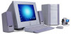
Provides safety and legal information about your computer's hard drive. VAIO Digital Studio Computer QuickStart Unpacking Your Computer Computer and Supplied Accessories Computer and accessories System Unit Display (Sold separately) Speakers Modem Cable Power Cord AC Adapter (Speaker) Keyboard Mouse Manuals ❑ VAIO Digital Studio™ Computer QuickStart - Contains information on unpacking and setting up your computer, supplementary updates, support information, and...
Provides safety and legal information about your computer's hard drive. VAIO Digital Studio Computer QuickStart Unpacking Your Computer Computer and Supplied Accessories Computer and accessories System Unit Display (Sold separately) Speakers Modem Cable Power Cord AC Adapter (Speaker) Keyboard Mouse Manuals ❑ VAIO Digital Studio™ Computer QuickStart - Contains information on unpacking and setting up your computer, supplementary updates, support information, and...
Quick Start Guide
Page 14
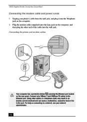
... into the Line jack on the rear panel. VAIO Digital Studio Computer QuickStart Connecting the modem cable and power cords 1 Unplug your network administrator. 14 Connecting the phone and modem cables 4 MONITOR 3 2 1 LINE TELEPHONE Your computer has a protective sticker covering the Ethernet port located on the computer, and then plug the other cables or a telephone... only 10Base-T and 100Base-TX cables to a network, see your phone's cable from the wall jack, and plug it into the Telephone jack on the computer. 2 Plug the modem cable (supplied) into the wall jack.
... into the Line jack on the rear panel. VAIO Digital Studio Computer QuickStart Connecting the modem cable and power cords 1 Unplug your network administrator. 14 Connecting the phone and modem cables 4 MONITOR 3 2 1 LINE TELEPHONE Your computer has a protective sticker covering the Ethernet port located on the computer, and then plug the other cables or a telephone... only 10Base-T and 100Base-TX cables to a network, see your phone's cable from the wall jack, and plug it into the Telephone jack on the computer. 2 Plug the modem cable (supplied) into the wall jack.
Quick Start Guide
Page 40
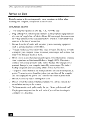
... its peripheral equipment into the same AC supply line. To remove power from the system, you will not be using the computer for your data during an electrical storm. ❑ If you live in this section provides basic procedures to your computer caused by the plug. VAIO Digital Studio Computer QuickStart Notes on Use The information...
... its peripheral equipment into the same AC supply line. To remove power from the system, you will not be using the computer for your data during an electrical storm. ❑ If you live in this section provides basic procedures to your computer caused by the plug. VAIO Digital Studio Computer QuickStart Notes on Use The information...

Quick Start Guide
Page 52
... VAIO Action Setup 27 VisualFlow 27 WordPerfect 27 SonicStage 26 Sony on Yahoo! 27 SonyStyle Connect 27 Stand by mode 19 surge protection 40 System Hibernate mode 20 System response problems 38 system upgrading 43 T Troubleshooting Change parallel port type 31 computer ...Recover drivers 29 Software problems 33, 34 starting the computer 29 System response 38 turning off computer 21 turning on computer 16 U Uninterruptible Power Supply 40 upgrading procedures 43 UPS 40 Utilities driver recovery 29 V VAIO AV Applications 5 VAIO Smart keyboard 6 ventilation 10 Viewing angle display 10 VisualFlow...
... VAIO Action Setup 27 VisualFlow 27 WordPerfect 27 SonicStage 26 Sony on Yahoo! 27 SonyStyle Connect 27 Stand by mode 19 surge protection 40 System Hibernate mode 20 System response problems 38 system upgrading 43 T Troubleshooting Change parallel port type 31 computer ...Recover drivers 29 Software problems 33, 34 starting the computer 29 System response 38 turning off computer 21 turning on computer 16 U Uninterruptible Power Supply 40 upgrading procedures 43 UPS 40 Utilities driver recovery 29 V VAIO AV Applications 5 VAIO Smart keyboard 6 ventilation 10 Viewing angle display 10 VisualFlow...
System Reference Manual
Page 10
System Board 47 Memory Module (DIMM) Slots 48 Power Supply and Aux Power Headers 49 CLR CMOS Jumper 51 Chapter 5 - CMOS Setup Options 53 Main Screen 55 Advanced Screen 57 Power Screen 59 Boot Screen 60 Exit Screen 61 Chapter 6 - x VAIO Digital Studio System Reference Manual Chapter 3 - Removing, Installing, and Replacing Components 23 Removing the Side... Messages 66 DMA Channel Assignments 68 System I /O Slot 38 Installing a 3.5-inch Internal Hard Disk Drive 39 To identify additional hard disk space 43 Removing the Power Supply 44 Replacing the Power Supply 45 Chapter 4 -
System Board 47 Memory Module (DIMM) Slots 48 Power Supply and Aux Power Headers 49 CLR CMOS Jumper 51 Chapter 5 - CMOS Setup Options 53 Main Screen 55 Advanced Screen 57 Power Screen 59 Boot Screen 60 Exit Screen 61 Chapter 6 - x VAIO Digital Studio System Reference Manual Chapter 3 - Removing, Installing, and Replacing Components 23 Removing the Side... Messages 66 DMA Channel Assignments 68 System I /O Slot 38 Installing a 3.5-inch Internal Hard Disk Drive 39 To identify additional hard disk space 43 Removing the Power Supply 44 Replacing the Power Supply 45 Chapter 4 -
System Reference Manual
Page 18
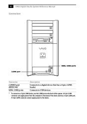
Connects to USB devices. * To connect to a digital device that has a 4-pin i.LINK header. 6 VAIO Digital Studio System Reference Manual Connectors i.LINK port USB1, USB2 ports Connector i.LINK® port (IEEE1394)* USB1, USB2 ports Description Connects to a 6-pin i.LINK device, use the i.LINK port on the back of the system. A 4-pin i.LINK connector cannot supply power to the device if the device also has a 6-pin i.LINK port. A 6-pin i.LINK connector can supply power from the computer to the device.
Connects to USB devices. * To connect to a digital device that has a 4-pin i.LINK header. 6 VAIO Digital Studio System Reference Manual Connectors i.LINK port USB1, USB2 ports Connector i.LINK® port (IEEE1394)* USB1, USB2 ports Description Connects to a 6-pin i.LINK device, use the i.LINK port on the back of the system. A 4-pin i.LINK connector cannot supply power to the device if the device also has a 6-pin i.LINK port. A 6-pin i.LINK connector can supply power from the computer to the device.

System Reference Manual
Page 36
24 VAIO Digital Studio System Reference Manual Removing the Side Cover You must remove the side cover to release front panel Pull out top a few inches, then lift out Pull out tab to access the system board, add-in cards, power supply, battery, memory, and internal drives. 1 From the rear of the unit, pull the metal tab shown in the next diagram. 2 Pull the top of the cover away from the unit about two inches, then gently lift out the cover.
24 VAIO Digital Studio System Reference Manual Removing the Side Cover You must remove the side cover to release front panel Pull out top a few inches, then lift out Pull out tab to access the system board, add-in cards, power supply, battery, memory, and internal drives. 1 From the rear of the unit, pull the metal tab shown in the next diagram. 2 Pull the top of the cover away from the unit about two inches, then gently lift out the cover.
System Reference Manual
Page 46
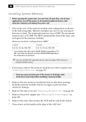
...32, 64, 128, 256 DIMM2 0, 8, 16, 32, 64, 128, 256 * Your computer ships with more than 128 MB SDRAM depending on the handle at least 128 MB. SDRAM is expandable to replace (see "Removing the Power Supply" on page 37). ! The maximum memory size is 8 MB. Your model may ship ...discharge static electricity in your body before handling a memory module. 3 Remove the new memory module(s) from its anti-static package. 34 VAIO Digital Studio System Reference Manual Installing System Memory ! The BIOS automatically detects the type, size and speed of the memory module and configuration...
...32, 64, 128, 256 DIMM2 0, 8, 16, 32, 64, 128, 256 * Your computer ships with more than 128 MB SDRAM depending on the handle at least 128 MB. SDRAM is expandable to replace (see "Removing the Power Supply" on page 37). ! The maximum memory size is 8 MB. Your model may ship ...discharge static electricity in your body before handling a memory module. 3 Remove the new memory module(s) from its anti-static package. 34 VAIO Digital Studio System Reference Manual Installing System Memory ! The BIOS automatically detects the type, size and speed of the memory module and configuration...
System Reference Manual
Page 48
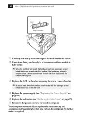
... the handle on the computer. 36 VAIO Digital Studio System Reference Manual Latch Edge Connectors 10 Carefully but firmly insert the edge of the module. No further action is straight up and locked into the slot on the AGP card. 13 Replace the power supply (see "Replacing the Power Supply" on page 45).... 14 Replace the side cover (see "Replacing the Side Cover" on page 25). 15 Reconnect the power cord and turn on the AGP slot is required.
... the handle on the computer. 36 VAIO Digital Studio System Reference Manual Latch Edge Connectors 10 Carefully but firmly insert the edge of the module. No further action is straight up and locked into the slot on the AGP card. 13 Replace the power supply (see "Replacing the Power Supply" on page 45).... 14 Replace the side cover (see "Replacing the Side Cover" on page 25). 15 Reconnect the power cord and turn on the AGP slot is required.

System Reference Manual
Page 52
40 VAIO Digital Studio System Reference Manual 3 Disconnect the drive connector (A in diagram). 5 Pull out on the tab (C) that secures the drive holder to the chassis. A B C Drive connector Power supply connector Tab Disk drive holder 4 Disconnect the power connector (B in diagram).
40 VAIO Digital Studio System Reference Manual 3 Disconnect the drive connector (A in diagram). 5 Pull out on the tab (C) that secures the drive holder to the chassis. A B C Drive connector Power supply connector Tab Disk drive holder 4 Disconnect the power connector (B in diagram).
System Reference Manual
Page 56
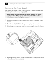
44 VAIO Digital Studio System Reference Manual Removing the Power Supply You remove the power supply when you insert a memory module (see "Installing System Memory" on top of the chassis. 2 Pull the tab (A) that latches the power supply to the chassis. 3 Slide the power supply up until the power supply clears the ... down and rest it on page 34). ! A 4 Rotate the power supply upside down the computer, and unplug the power cord. 1 Remove the screw that secures the power supply to all open applications, turn off the power to the rear of the chassis where the hard drive is located.
44 VAIO Digital Studio System Reference Manual Removing the Power Supply You remove the power supply when you insert a memory module (see "Installing System Memory" on top of the chassis. 2 Pull the tab (A) that latches the power supply to the chassis. 3 Slide the power supply up until the power supply clears the ... down and rest it on page 34). ! A 4 Rotate the power supply upside down the computer, and unplug the power cord. 1 Remove the screw that secures the power supply to all open applications, turn off the power to the rear of the chassis where the hard drive is located.

System Reference Manual
Page 62
50 VAIO Digital Studio System Reference Manual Power Supply header (Continued) Pin Signal Name 17 Ground 18 No Connection 19 +5 V 20 +5 V Aux Power header Pin Signal Name 1 Ground 2 Ground 3 +12 V 4 +12 V
50 VAIO Digital Studio System Reference Manual Power Supply header (Continued) Pin Signal Name 17 Ground 18 No Connection 19 +5 V 20 +5 V Aux Power header Pin Signal Name 1 Ground 2 Ground 3 +12 V 4 +12 V
VAIO User Guide
Page 60
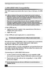
...Sony computer supplies, accessories, and peripherals can : ❑ supply power from the Sony VAIO Direct Web site at http://vaio.sonystyle.com, or by the 6-pin i.LINK port cannot exceed 6 watts. The i.LINK connection may include either 4-pin or 6-pin, or both types, of i.LINK ports. ✍ i.LINK is equipped with your computer...into this port. 2 Plug the other . The total power supplied by calling 1-888-315-7669 (toll free). Connecting an i.LINK (IEEE1394) device 1 Use the symbol to your computer. The following Sony i.LINK 400 Mbps cables are available and recommended for ...
...Sony computer supplies, accessories, and peripherals can : ❑ supply power from the Sony VAIO Direct Web site at http://vaio.sonystyle.com, or by the 6-pin i.LINK port cannot exceed 6 watts. The i.LINK connection may include either 4-pin or 6-pin, or both types, of i.LINK ports. ✍ i.LINK is equipped with your computer...into this port. 2 Plug the other . The total power supplied by calling 1-888-315-7669 (toll free). Connecting an i.LINK (IEEE1394) device 1 Use the symbol to your computer. The following Sony i.LINK 400 Mbps cables are available and recommended for ...
VAIO User Guide
Page 92
... 77 recover applications 67 software audio problems 72 startup problems 67 system response 77 Topics 67 turning off your computer 79 TV interference 81 U Uninterruptible Power Supply 79 Universal Serial Bus ports 9 upgrading your computer 81 UPS 79 USB port 9 92 V VAIO Action Setup 13 ventilation 80 VisualFlow software 56 navigating 56 voltage settings 79
... 77 recover applications 67 software audio problems 72 startup problems 67 system response 77 Topics 67 turning off your computer 79 TV interference 81 U Uninterruptible Power Supply 79 Universal Serial Bus ports 9 upgrading your computer 81 UPS 79 USB port 9 92 V VAIO Action Setup 13 ventilation 80 VisualFlow software 56 navigating 56 voltage settings 79


