
System Reference Manual
Page 2
... and serial number are trademarks of Intel Corporation. Refer to Users © 2001 Sony Electronics Inc. Model Numbers: PCV-RX462DS/ PCV-RX463DS/PCV-RX465DS/ PCV-RX470DS/PCV-RX480DS/ PCV-RX490TV Serial Number ii All other trademarks are registered trademarks of their respective owners.... Notice to the model and serial number when you call your VAIO® computer. SONY ELECTRONICS INC. ...
... and serial number are trademarks of Intel Corporation. Refer to Users © 2001 Sony Electronics Inc. Model Numbers: PCV-RX462DS/ PCV-RX463DS/PCV-RX465DS/ PCV-RX470DS/PCV-RX480DS/ PCV-RX490TV Serial Number ii All other trademarks are registered trademarks of their respective owners.... Notice to the model and serial number when you call your VAIO® computer. SONY ELECTRONICS INC. ...

System Reference Manual
Page 3
...and Caution DVD-ROM Laser Diode Properties (PCV-RX462DS/PCV-RX463DS/ PCV-RX465DS/PCV-RX470DS/ PCV-RX480DS) Laser output Wave Length 0.4 mW (DVD) 0.14 mW (CD) 650-655 nm (DVD) 785 nm (CD) CD-RW Laser Diode Properties (PCV-RX462DS/PCV-RX463DS/ PCV-RX465DS/PCV-RX470DS/ PCV-RX480DS) Laser output Wave Length 1.0 mW ...(Read) 43.5 mW (Write) 780-787 nm DVD-RW Laser Diode Properties (PCV-RX490TV) Laser output 1.3 mW (CD-read) 1.1 mW (DVD-read) ...
...and Caution DVD-ROM Laser Diode Properties (PCV-RX462DS/PCV-RX463DS/ PCV-RX465DS/PCV-RX470DS/ PCV-RX480DS) Laser output Wave Length 0.4 mW (DVD) 0.14 mW (CD) 650-655 nm (DVD) 785 nm (CD) CD-RW Laser Diode Properties (PCV-RX462DS/PCV-RX463DS/ PCV-RX465DS/PCV-RX470DS/ PCV-RX480DS) Laser output Wave Length 1.0 mW ...(Read) 43.5 mW (Write) 780-787 nm DVD-RW Laser Diode Properties (PCV-RX490TV) Laser output 1.3 mW (CD-read) 1.1 mW (DVD-read) ...

System Reference Manual
Page 5
... to provide reasonable protection against harmful interference in Canada. Operation is subject to comply with Part 15 of Conformity Trade Name: SONY Model No.: PCV-RX462DS PCV-RX463DS PCV-RX465DS PCV-RX470DS PCV-RX480DS PCV-RX490TV Responsible Party: Sony Electronics Inc. This equipment has been tested and found to the two following two conditions: (1) This device may not cause...
... to provide reasonable protection against harmful interference in Canada. Operation is subject to comply with Part 15 of Conformity Trade Name: SONY Model No.: PCV-RX462DS PCV-RX463DS PCV-RX465DS PCV-RX470DS PCV-RX480DS PCV-RX490TV Responsible Party: Sony Electronics Inc. This equipment has been tested and found to the two following two conditions: (1) This device may not cause...
System Reference Manual
Page 6
The FCC Ringer Equivalence Number (REN) for this equipment is not practical, the telephone company will notify the customer as soon as possible. But if advance notice is 0.79 B (for Lucent modem), or 0.0 B (for HomePNA modem). interference to radio or television reception, which can be determined by turning the equipment off and on, the user is encouraged to try to correct the interference by the total RENs, contact the telephone company to determine the maximum REN for the calling area. Operation with cables, connected to radio and television reception. FCC Part 68 This ...
The FCC Ringer Equivalence Number (REN) for this equipment is not practical, the telephone company will notify the customer as soon as possible. But if advance notice is 0.79 B (for Lucent modem), or 0.0 B (for HomePNA modem). interference to radio or television reception, which can be determined by turning the equipment off and on, the user is encouraged to try to correct the interference by the total RENs, contact the telephone company to determine the maximum REN for the calling area. Operation with cables, connected to radio and television reception. FCC Part 68 This ...

System Reference Manual
Page 7
... of the transmission, the date and time it unlawful for repair or warranty information, please contact 1-888-4SONY-PC, or write to the Sony Customer Information Center, 12451 Gateway Blvd., Fort Myers, FL 33913. This Class B digital apparatus complies with this modem, for any message via...or 'Terms of each transmitted page or on public coin service provided by a Sony Service Center or Sony authorized agent. Disposal of Lithium Battery You can return your unwanted lithium batteries to your nearest Sony Service Center or Factory Service Center. ✍ In some areas the disposal of...
... of the transmission, the date and time it unlawful for repair or warranty information, please contact 1-888-4SONY-PC, or write to the Sony Customer Information Center, 12451 Gateway Blvd., Fort Myers, FL 33913. This Class B digital apparatus complies with this modem, for any message via...or 'Terms of each transmitted page or on public coin service provided by a Sony Service Center or Sony authorized agent. Disposal of Lithium Battery You can return your unwanted lithium batteries to your nearest Sony Service Center or Factory Service Center. ✍ In some areas the disposal of...

System Reference Manual
Page 9
The Ringer Equivalence Number for this equipment is permissible to be connected to the facilities of the power utility, telephone lines and internal metallic water pipe system, if present, are connected together. Avis de L'industrie Canada AVIS: L'étiquette d'Industrie Canada identifie le matériel homologué. Le matériel doit également être installé en suivant une méthode acceptée de raccordement. Les réparations de matériel homologué doivent être coordonnées par un représentant désigné par le ...
The Ringer Equivalence Number for this equipment is permissible to be connected to the facilities of the power utility, telephone lines and internal metallic water pipe system, if present, are connected together. Avis de L'industrie Canada AVIS: L'étiquette d'Industrie Canada identifie le matériel homologué. Le matériel doit également être installé en suivant une méthode acceptée de raccordement. Les réparations de matériel homologué doivent être coordonnées par un représentant désigné par le ...
System Reference Manual
Page 11
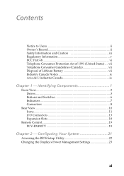
... 23 xi Identifying Components 1 Front View...2 Drives ...3 Buttons and Switches 6 Indicators 7 Connectors 8 Rear View 10 Icons ...11 I/O Connectors 13 Expansion Slots 18 Remote Control 19 PCV-RX490TV 19 Chapter 2 - Contents Notice to Users ii Owner's Record ii Safety Information and Caution iii Regulatory Information v FCC Part 68 vi Telephone Consumer Protection...
... 23 xi Identifying Components 1 Front View...2 Drives ...3 Buttons and Switches 6 Indicators 7 Connectors 8 Rear View 10 Icons ...11 I/O Connectors 13 Expansion Slots 18 Remote Control 19 PCV-RX490TV 19 Chapter 2 - Contents Notice to Users ii Owner's Record ii Safety Information and Caution iii Regulatory Information v FCC Part 68 vi Telephone Consumer Protection...

System Reference Manual
Page 12
...Slot Cover 43 Covering an Open I/O Slot 44 Installing a 3.5-inch Internal Hard Disk Drive 45 To prepare a startup disk (PCV-RX490TV model only 45 To install a 3.5-inch internal hard disk drive (all models 46 To set up the new hard ...drive with the startup disk (PCV-RX490TV model only 49 To identify the additional hard disk space for Giga Pocket use (PCV-RX490TV model only 49 Removing the Power Supply 50 Replacing the Power Supply...Headers 72 CD-IN Header 73 AUX-IN Header 74 Video Header 75 xii VAIO Digital Studio™ System Reference Manual Chapter 3 -
...Slot Cover 43 Covering an Open I/O Slot 44 Installing a 3.5-inch Internal Hard Disk Drive 45 To prepare a startup disk (PCV-RX490TV model only 45 To install a 3.5-inch internal hard disk drive (all models 46 To set up the new hard ...drive with the startup disk (PCV-RX490TV model only 49 To identify the additional hard disk space for Giga Pocket use (PCV-RX490TV model only 49 Removing the Power Supply 50 Replacing the Power Supply...Headers 72 CD-IN Header 73 AUX-IN Header 74 Video Header 75 xii VAIO Digital Studio™ System Reference Manual Chapter 3 -
System Reference Manual
Page 13
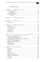
Giga Pocket Card 81 Chapter 7 - Miscellaneous Technical Information ......... 95 User and Supervisor Passwords 96 Beep Code Error Messages 97 PCI Configuration Status and Error Messages 98 DMA Channel Assignments 100 System I/O Address Map 101 Memory Map 105 IRQ Summary 107 Chapter 10 - CMOS Setup Options 85 Main Screen 87 Advanced Screen 89 Power Screen 92 Boot Screen 93 Exit Screen 94 Chapter 9 - Specifications 109 Processors 109 Chipset ...109 AGP Bus 109 PCI Bus ...110 Memory Modules 110 Memory Configurations 110 L2 Cache 110 Graphics 110 Video Card 83 ...
Giga Pocket Card 81 Chapter 7 - Miscellaneous Technical Information ......... 95 User and Supervisor Passwords 96 Beep Code Error Messages 97 PCI Configuration Status and Error Messages 98 DMA Channel Assignments 100 System I/O Address Map 101 Memory Map 105 IRQ Summary 107 Chapter 10 - CMOS Setup Options 85 Main Screen 87 Advanced Screen 89 Power Screen 92 Boot Screen 93 Exit Screen 94 Chapter 9 - Specifications 109 Processors 109 Chipset ...109 AGP Bus 109 PCI Bus ...110 Memory Modules 110 Memory Configurations 110 L2 Cache 110 Graphics 110 Video Card 83 ...

System Reference Manual
Page 14
xiv VAIO Digital Studio™ System Reference Manual Audio ...111 Communications 112 Giga Pocket I/O (PCV-RX490TV only 112 I/O and Expansion Slots 112 Floppy Disk Drive and Controller 113 Hard Drives and Controllers 113 Optical Drives 114 System BIOS 116 Index 117
xiv VAIO Digital Studio™ System Reference Manual Audio ...111 Communications 112 Giga Pocket I/O (PCV-RX490TV only 112 I/O and Expansion Slots 112 Floppy Disk Drive and Controller 113 Hard Drives and Controllers 113 Optical Drives 114 System BIOS 116 Index 117
System Reference Manual
Page 15
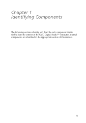
Internal components are identified in the appropriate section of the VAIO Digital Studio™ computer. Chapter 1 Identifying Components The following sections identify and describe each component that is visible from the exterior of this manual. 1
Internal components are identified in the appropriate section of the VAIO Digital Studio™ computer. Chapter 1 Identifying Components The following sections identify and describe each component that is visible from the exterior of this manual. 1

System Reference Manual
Page 16
2 VAIO Digital Studio™ System Reference Manual Front View All Models
2 VAIO Digital Studio™ System Reference Manual Front View All Models
System Reference Manual
Page 17
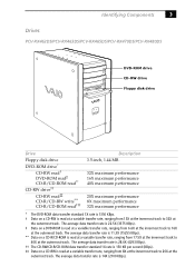
Identifying Components 3 Drives PCV-RX462DS/PCV-RX463DS/PCV-RX465DS/PCV-RX470DS/PCV-RX480DS DVD-ROM drive CD-RW drive Floppy disk drive Drive Floppy disk drive DVD-ROM drive* CD-RW read† DVD-ROM read‡ ... read** CD-RW drive†† CD-RW read‡‡ CD-R/CD-RW write*** CD-R/CD-ROM read††† Description 3.5-inch, 1.44 MB. 32X maximum performance 16X maximum performance 40X maximum performance 20X maximum performance 8X maximum performance 32X maximum performance * The DVD-ROM data transfer standard 1X...
Identifying Components 3 Drives PCV-RX462DS/PCV-RX463DS/PCV-RX465DS/PCV-RX470DS/PCV-RX480DS DVD-ROM drive CD-RW drive Floppy disk drive Drive Floppy disk drive DVD-ROM drive* CD-RW read† DVD-ROM read‡ ... read** CD-RW drive†† CD-RW read‡‡ CD-R/CD-RW write*** CD-R/CD-ROM read††† Description 3.5-inch, 1.44 MB. 32X maximum performance 16X maximum performance 40X maximum performance 20X maximum performance 8X maximum performance 32X maximum performance * The DVD-ROM data transfer standard 1X...

System Reference Manual
Page 18
PCV-RX490TV DVD-RW drive CD-ROM drive Floppy disk drive Drive Floppy disk drive DVD-... to 32X at a constant transfer rate of 2X, 4X, 8X (max. The average data transfer rate is 150 KBps. 4 VAIO Digital Studio™ System Reference Manual ***Data on a CD-R/CD-ROM is read †† CD-R write CD-RW write‡...RW write CD-ROM drive CD-R/CD-ROM††† CD-RW‡‡‡ Description 3.5-inch, 1.44 MB. 4X maximum performance 2X maximum performance 24X maximum performance 16X maximum performance 8X maximum performance 4X maximum performance 2X maximum performance ...
PCV-RX490TV DVD-RW drive CD-ROM drive Floppy disk drive Drive Floppy disk drive DVD-... to 32X at a constant transfer rate of 2X, 4X, 8X (max. The average data transfer rate is 150 KBps. 4 VAIO Digital Studio™ System Reference Manual ***Data on a CD-R/CD-ROM is read †† CD-R write CD-RW write‡...RW write CD-ROM drive CD-R/CD-ROM††† CD-RW‡‡‡ Description 3.5-inch, 1.44 MB. 4X maximum performance 2X maximum performance 24X maximum performance 16X maximum performance 8X maximum performance 4X maximum performance 2X maximum performance ...

System Reference Manual
Page 19
High-speed writing to a CD-RW disc is not supported. ***Data on a DVD-RW/DVD-R is written at the outermost track. The average data transfer rate is read at a variable transfer rate, ranging from 6.9X at the innermost track to 16X at the outermost track. The average data transfer rate is 3.3X (4455 KBps). ‡ Data on a DVD-RW/DVD-R is read at a constant transfer rate of 2X. ** Data on a CD-ROM is read at a variable transfer rate, ranging from 10.3X at the innermost track to 24X at a constant transfer rate of 4X (max for CD-RW), or 8X depending on the speed you select. The average data...
High-speed writing to a CD-RW disc is not supported. ***Data on a DVD-RW/DVD-R is written at the outermost track. The average data transfer rate is read at a variable transfer rate, ranging from 6.9X at the innermost track to 16X at the outermost track. The average data transfer rate is 3.3X (4455 KBps). ‡ Data on a DVD-RW/DVD-R is read at a constant transfer rate of 2X. ** Data on a CD-ROM is read at a variable transfer rate, ranging from 10.3X at the innermost track to 24X at a constant transfer rate of 4X (max for CD-RW), or 8X depending on the speed you select. The average data...
System Reference Manual
Page 20
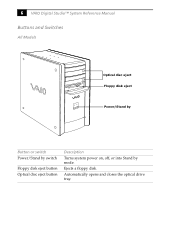
6 VAIO Digital Studio™ System Reference Manual Buttons and Switches All Models Optical disc eject Floppy disk eject Power/Stand by Button or switch Power/Stand by switch Floppy disk eject button Optical disc eject button Description Turns system power on, off, or into Stand by mode. Automatically opens and closes the optical drive tray. Ejects a floppy disk.
6 VAIO Digital Studio™ System Reference Manual Buttons and Switches All Models Optical disc eject Floppy disk eject Power/Stand by Button or switch Power/Stand by switch Floppy disk eject button Optical disc eject button Description Turns system power on, off, or into Stand by mode. Automatically opens and closes the optical drive tray. Ejects a floppy disk.

System Reference Manual
Page 21
Indicators All Models Identifying Components 7 Floppy disk drive access Hard disk drive access Optical disc drive access Power/Stand by Indicator Power/Stand by indicator Floppy disk drive access indicator Optical drive access indicator Hard disk drive access indicator Description Stand by (red) indicates the computer is turned off, or in Stand by mode, ready to use. On (red) indicates optical drive activity. Off (no color) indicates the computer is in hibernation mode. On (green) indicates floppy disk drive activity. On (blue) indicates the computer is out of Stand by mode....
Indicators All Models Identifying Components 7 Floppy disk drive access Hard disk drive access Optical disc drive access Power/Stand by Indicator Power/Stand by indicator Floppy disk drive access indicator Optical drive access indicator Hard disk drive access indicator Description Stand by (red) indicates the computer is turned off, or in Stand by mode, ready to use. On (red) indicates optical drive activity. Off (no color) indicates the computer is in hibernation mode. On (green) indicates floppy disk drive activity. On (blue) indicates the computer is out of Stand by mode....

System Reference Manual
Page 22
A 4-pin i.LINK header cannot supply power to a 6-pin i.LINK device, use the i.LINK header on the back of the system. Connects to USB devices. * To connect to the device. A 6-pin i.LINK header can supply power from the computer to a digital device that has a 4-pin i.LINK header. 8 VAIO Digital Studio™ System Reference Manual Connectors PCV-RX462DS/PCV-RX463DS/PCV-RX465DS/PCV-RX470DS/PCV-RX480DS USB3, USB4 i.LINK Connector i.LINK® (IEEE1394)* USB3, USB4 Description Connects to the device if the device also has a 6-pin i.LINK header.
A 4-pin i.LINK header cannot supply power to a 6-pin i.LINK device, use the i.LINK header on the back of the system. Connects to USB devices. * To connect to the device. A 6-pin i.LINK header can supply power from the computer to a digital device that has a 4-pin i.LINK header. 8 VAIO Digital Studio™ System Reference Manual Connectors PCV-RX462DS/PCV-RX463DS/PCV-RX465DS/PCV-RX470DS/PCV-RX480DS USB3, USB4 i.LINK Connector i.LINK® (IEEE1394)* USB3, USB4 Description Connects to the device if the device also has a 6-pin i.LINK header.

System Reference Manual
Page 23
Connects to a digital device that has a 4-pin i.LINK connector. Connects to an S-video cable (optional). Connects to a video cable (supplied). Connects to an audio cable (supplied). PCV-RX490TV Identifying Components 9 USB i.LINK Video/Audio Inputs Connector Universal Serial Bus (USB) ports (2) i.LINK (4-pin) port (IEEE1394) S-Video In port Video In jack Audio L In jack/ Audio R In jack Description Connects to USB devices.
Connects to a digital device that has a 4-pin i.LINK connector. Connects to an S-video cable (optional). Connects to a video cable (supplied). Connects to an audio cable (supplied). PCV-RX490TV Identifying Components 9 USB i.LINK Video/Audio Inputs Connector Universal Serial Bus (USB) ports (2) i.LINK (4-pin) port (IEEE1394) S-Video In port Video In jack Audio L In jack/ Audio R In jack Description Connects to USB devices.

System Reference Manual
Page 24
10 VAIO Digital Studio™ System Reference Manual Rear View All Models Mouse Keyboard USB1, USB2 Ethernet Serial Printer /Parallel i.LINK (IEEE394) Game/MIDI Headphones Line In Microphone Monitor Audio Out Video/S-video Out* Audio In Video/S-Video In* Line Power DVI VHF/UHF* Telephone** *Only in PCV-RX490TV Model ** In models with an HPNA modem, the telephone line jack does not exist.
10 VAIO Digital Studio™ System Reference Manual Rear View All Models Mouse Keyboard USB1, USB2 Ethernet Serial Printer /Parallel i.LINK (IEEE394) Game/MIDI Headphones Line In Microphone Monitor Audio Out Video/S-video Out* Audio In Video/S-Video In* Line Power DVI VHF/UHF* Telephone** *Only in PCV-RX490TV Model ** In models with an HPNA modem, the telephone line jack does not exist.