
System Reference Manual
Page 2
...of their respective owners. Model Number: PCV-LX810/PCV-LX910 Serial Number Subscriptions to the terms and conditions of such software is prohibited. Sony, VAIO, the VAIO logo, VAIO Slimtop, Memory Stick, the Memory Stick logo, and i.LINK are trademarks of Sony. Reproduction in whole or in part...product. ii Notice to the model and serial number when you call your VAIO® computer. reserves the right to make any modification to current retail versions. SONY ELECTRONICS INC. Sony Electronics Inc. The software described herein is a registered trademark of a separate ...
...of their respective owners. Model Number: PCV-LX810/PCV-LX910 Serial Number Subscriptions to the terms and conditions of such software is prohibited. Sony, VAIO, the VAIO logo, VAIO Slimtop, Memory Stick, the Memory Stick logo, and i.LINK are trademarks of Sony. Reproduction in whole or in part...product. ii Notice to the model and serial number when you call your VAIO® computer. reserves the right to make any modification to current retail versions. SONY ELECTRONICS INC. Sony Electronics Inc. The software described herein is a registered trademark of a separate ...

System Reference Manual
Page 3
..., use only No. 26 AWG or larger telecommunication line cord. For CD-RW/DVD combo drive: Danger - Invisible laser radiation when open . iii VAIO Slimtop™ System Reference Manual Safety Information and Caution CD-RW/DVD Combo Drive Laser Diode Properties Laser Output (CD-RW) 1.08 mW (Read) 32 ... Wave Length (CD-RW) 780 nm Wave Length (DVD-ROM) 650 nm ❑ To prevent fire or shock hazard, do not expose your nearest Sony Service Center. ! The use the modem or a telephone to report a gas leak in this product will increase eye hazard. Visible and invisible laser radiation ...
..., use only No. 26 AWG or larger telecommunication line cord. For CD-RW/DVD combo drive: Danger - Invisible laser radiation when open . iii VAIO Slimtop™ System Reference Manual Safety Information and Caution CD-RW/DVD Combo Drive Laser Diode Properties Laser Output (CD-RW) 1.08 mW (Read) 32 ... Wave Length (CD-RW) 780 nm Wave Length (DVD-ROM) 650 nm ❑ To prevent fire or shock hazard, do not expose your nearest Sony Service Center. ! The use the modem or a telephone to report a gas leak in this product will increase eye hazard. Visible and invisible laser radiation ...
System Reference Manual
Page 5
...may cause undesired operation. This device complies with cables, connected to peripherals, that interference will not occur in this computer product. If this equipment does cause harmful interference to radio or television reception, which the receiver is encouraged to try... the limits for FCC-related matters only. Operation with Part 15 of Conformity Trade Name: SONY Model No.: PCV-LX810/PCV-LX910 Responsible Party: Sony Electronics Inc. v VAIO Slimtop™ System Reference Manual Regulatory Information Declaration of FCC Rules. These limits are designed to ...
...may cause undesired operation. This device complies with cables, connected to peripherals, that interference will not occur in this computer product. If this equipment does cause harmful interference to radio or television reception, which the receiver is encouraged to try... the limits for FCC-related matters only. Operation with Part 15 of Conformity Trade Name: SONY Model No.: PCV-LX810/PCV-LX910 Responsible Party: Sony Electronics Inc. v VAIO Slimtop™ System Reference Manual Regulatory Information Declaration of FCC Rules. These limits are designed to ...

System Reference Manual
Page 7
... remplacer seulement par une batterie identique ou de type équivalent recommandé par le fabricant. Évacuer les batteries us ée. vii VAIO Slimtop™ System Reference Manual Telephone Consumer Guidelines (Canada) Please refer to your telephone directory under 'Privacy Issues' and/or 'Terms of explosion if ... contact: CRTC Terrasses de la Chaudiére, Tour centrale 1 promenade du Portage, 5 étage Hull PQ K1A 0N2. For the Sony Service Center nearest you, call 1888-476-6972 in the United States or 1-800-9617669 in this device may be prohibited. Garder hors de ...
... remplacer seulement par une batterie identique ou de type équivalent recommandé par le fabricant. Évacuer les batteries us ée. vii VAIO Slimtop™ System Reference Manual Telephone Consumer Guidelines (Canada) Please refer to your telephone directory under 'Privacy Issues' and/or 'Terms of explosion if ... contact: CRTC Terrasses de la Chaudiére, Tour centrale 1 promenade du Portage, 5 étage Hull PQ K1A 0N2. For the Sony Service Center nearest you, call 1888-476-6972 in the United States or 1-800-9617669 in this device may be prohibited. Garder hors de ...

System Reference Manual
Page 12
Fax/Modem Card xii VAIO Slimtop™ System Reference Manual Chapter 3 - System Board Connectors 46 Front Panel Header 46 IDE Connectors 47 PCI Slot Connectors 48 Memory Module (DIMM) Connectors 49 ...) Connectors 51 USB Connectors 52 VGA MONITOR Connector 53 LCD Connector 54 Wake On LAN (WOL_CON) Connector 55 PHONES, LINE IN, and MIC Connectors 56 Sony Memory Stick Media Slot Connector 57 i.LINK Interface Header Connectors 57 i.LINK Connectors 59 CD-In Connector 60 Configuration Switches 61 Chapter 5 - Removing, Installing, and...
Fax/Modem Card xii VAIO Slimtop™ System Reference Manual Chapter 3 - System Board Connectors 46 Front Panel Header 46 IDE Connectors 47 PCI Slot Connectors 48 Memory Module (DIMM) Connectors 49 ...) Connectors 51 USB Connectors 52 VGA MONITOR Connector 53 LCD Connector 54 Wake On LAN (WOL_CON) Connector 55 PHONES, LINE IN, and MIC Connectors 56 Sony Memory Stick Media Slot Connector 57 i.LINK Interface Header Connectors 57 i.LINK Connectors 59 CD-In Connector 60 Configuration Switches 61 Chapter 5 - Removing, Installing, and...

System Reference Manual
Page 18
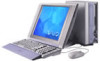
4 VAIO Slimtop™ System Reference Manual Buttons and Switches CD-RW/DVD combo drive disc eject PC card eject Power on/off Button or switch Power/Stand by switch CD-RW/DVD combo drive disc eject button PC card eject button Description Turns system power on and off. Ejects a PCMCIA card. Automatically opens the CD-RW/DVD combo drive tray.
4 VAIO Slimtop™ System Reference Manual Buttons and Switches CD-RW/DVD combo drive disc eject PC card eject Power on/off Button or switch Power/Stand by switch CD-RW/DVD combo drive disc eject button PC card eject button Description Turns system power on and off. Ejects a PCMCIA card. Automatically opens the CD-RW/DVD combo drive tray.

System Reference Manual
Page 20
A 6-pin i.LINK connector can supply power from the computer to the device. A 4-pin i.LINK connector cannot supply power to the device if the device also has a 6-pin i.LINK connector. Connects to USB devices. * To connect to digital devices that have a 4-pin i.LINK connector. 6 VAIO Slimtop™ System Reference Manual Connectors USB4 i.LINK Connector i.LINK® (IEEE1394)* USB4 Description Connects to a 6-pin i.LINK device, use the i.LINK connector on the back of the system.
A 6-pin i.LINK connector can supply power from the computer to the device. A 4-pin i.LINK connector cannot supply power to the device if the device also has a 6-pin i.LINK connector. Connects to USB devices. * To connect to digital devices that have a 4-pin i.LINK connector. 6 VAIO Slimtop™ System Reference Manual Connectors USB4 i.LINK Connector i.LINK® (IEEE1394)* USB4 Description Connects to a 6-pin i.LINK device, use the i.LINK connector on the back of the system.

System Reference Manual
Page 22
Connects to phone cable from wall jack. Connects to USB devices. Connects to headphones. Connects to USB devices. Connects to output connector on audio device. Connects to telephone. Connects to RJ-45 Ethernet connector. Connects to VGA monitor (optional). Connects to microphone connector on audio device. 8 VAIO Slimtop™ System Reference Manual Rear View MONITOR USB1 USB2 PHONES LINE IN MIC i.LINK LCD Connector Power ETHERNET LINE PHONE USB3 MONITOR USB1, USB2 PHONES LINE IN MIC Power ETHERNET LINE PHONE USB3 Description AC input power.
Connects to phone cable from wall jack. Connects to USB devices. Connects to headphones. Connects to USB devices. Connects to output connector on audio device. Connects to telephone. Connects to RJ-45 Ethernet connector. Connects to VGA monitor (optional). Connects to microphone connector on audio device. 8 VAIO Slimtop™ System Reference Manual Rear View MONITOR USB1 USB2 PHONES LINE IN MIC i.LINK LCD Connector Power ETHERNET LINE PHONE USB3 MONITOR USB1, USB2 PHONES LINE IN MIC Power ETHERNET LINE PHONE USB3 Description AC input power.

System Reference Manual
Page 24
... accessible from the rear panel. USB Connectors A total of the base next to the Ethernet connector, and USB3 is located on the Sony Pen Tablet or LCD display on Modem card at rear panel USB3 USB4 USB2 USB1 Rear panel Right side of front panel on the ...located on the front panel between the i.LINK connector and the Sony Memory Stick media slot. MONITOR Connector The MONITOR connector is a standard 15-pin female high-density VGA-type connector and is located on the rear panel. 10 VAIO Slimtop™ System Reference Manual I/O Connectors The following section identifies the...
... accessible from the rear panel. USB Connectors A total of the base next to the Ethernet connector, and USB3 is located on the Sony Pen Tablet or LCD display on Modem card at rear panel USB3 USB4 USB2 USB1 Rear panel Right side of front panel on the ...located on the front panel between the i.LINK connector and the Sony Memory Stick media slot. MONITOR Connector The MONITOR connector is a standard 15-pin female high-density VGA-type connector and is located on the rear panel. 10 VAIO Slimtop™ System Reference Manual I/O Connectors The following section identifies the...

System Reference Manual
Page 26
...Do not connect any other display to a telephone. They are physically identical and have identical connections. This connector is only for connecting the computer to this port. These jacks are located on the rear panel connects to a 10Base-T/100Base-TX Fast Ethernet network via an RJ-45 ... jack is for connecting to a telephone line that comes from the wall jack, and the PHONE jack is located on the rear panel. ! 12 VAIO Slimtop™ System Reference Manual 6-pin i.LINK (IEEE1394) On rear panel 4-pin i.LINK (IEEE1394) On front panel Ethernet Connector The Ethernet connector on the...
...Do not connect any other display to a telephone. They are physically identical and have identical connections. This connector is only for connecting the computer to this port. These jacks are located on the rear panel connects to a 10Base-T/100Base-TX Fast Ethernet network via an RJ-45 ... jack is for connecting to a telephone line that comes from the wall jack, and the PHONE jack is located on the rear panel. ! 12 VAIO Slimtop™ System Reference Manual 6-pin i.LINK (IEEE1394) On rear panel 4-pin i.LINK (IEEE1394) On front panel Ethernet Connector The Ethernet connector on the...

System Reference Manual
Page 30
...). ! Save and close all applications before rebooting the system. 1 Reboot the system. 2 Press F2 when the Sony screen appears. 3 Use the left and right arrow keys to select an item from the Exit menu. 16 VAIO Slimtop™ System Reference Manual Accessing the CMOS Setup Utility You must access the CMOS Setup Utility...
...). ! Save and close all applications before rebooting the system. 1 Reboot the system. 2 Press F2 when the Sony screen appears. 3 Use the left and right arrow keys to select an item from the Exit menu. 16 VAIO Slimtop™ System Reference Manual Accessing the CMOS Setup Utility You must access the CMOS Setup Utility...

System Reference Manual
Page 32
The System stand by when your computer is running on AC power. Power is reactivated when you push the power button. 3 To save a new power scheme, first modify the settings, click Save ... minutes) that you want to elapse before your computer goes on Stand by option allows you to specify the period of inactivity (in minutes) that you want to specify the period of inactivity (in minutes) before your computer goes into the Hibernate mode. 18 VAIO Slimtop™ System Reference Manual The Turn off when...
The System stand by when your computer is running on AC power. Power is reactivated when you push the power button. 3 To save a new power scheme, first modify the settings, click Save ... minutes) that you want to elapse before your computer goes on Stand by option allows you to specify the period of inactivity (in minutes) that you want to specify the period of inactivity (in minutes) before your computer goes into the Hibernate mode. 18 VAIO Slimtop™ System Reference Manual The Turn off when...

System Reference Manual
Page 34
... Clear position, the password that is stored in card, you install a VGA PCI add-in CMOS is controlled by a technical support or service technician. ! 20 VAIO Slimtop™ System Reference Manual Configuring the System Board ✍ The configuration should never need changing unless otherwise directed by a supervisor password or user password. The... Central Processing Unit (CPU) input clock is forced to remain at all attached peripheral devices, shut down the computer, and unplug the power cord. The CMOS and NVRAM settings are cleared.
... Clear position, the password that is stored in card, you install a VGA PCI add-in CMOS is controlled by a technical support or service technician. ! 20 VAIO Slimtop™ System Reference Manual Configuring the System Board ✍ The configuration should never need changing unless otherwise directed by a supervisor password or user password. The... Central Processing Unit (CPU) input clock is forced to remain at all attached peripheral devices, shut down the computer, and unplug the power cord. The CMOS and NVRAM settings are cleared.

System Reference Manual
Page 38
24 VAIO Slimtop™ System Reference Manual Removing the System Cover You must remove the system cover to access the system board, add-in cards, power supply, battery, and internal drives. 1 Remove the screw that secures the panel to the chassis (see item 1 in diagram), and set it aside for future use. 2 From the rear of the unit, hold down the system cover while you pull on the handle located at the rear panel (see item 2 in diagram). 3 Slide the system chassis out. 1 2
24 VAIO Slimtop™ System Reference Manual Removing the System Cover You must remove the system cover to access the system board, add-in cards, power supply, battery, and internal drives. 1 Remove the screw that secures the panel to the chassis (see item 1 in diagram), and set it aside for future use. 2 From the rear of the unit, hold down the system cover while you pull on the handle located at the rear panel (see item 2 in diagram). 3 Slide the system chassis out. 1 2

System Reference Manual
Page 40
...). 6 Turn on page 42). 3 Insert the add-in card into the slot at the bottom of the bracket fits into the PCI slot connector. 26 VAIO Slimtop™ System Reference Manual Installing an Add-In Card ! Before opening the system unit, save and close all open files, exit all open applications, turn... off the power to all attached peripheral devices, shut down the computer, and unplug the power cord. 1 Remove the system cover (see "Removing the System Cover" on page 24). 2 Remove the slot cover adjacent to the ...
...). 6 Turn on page 42). 3 Insert the add-in card into the slot at the bottom of the bracket fits into the PCI slot connector. 26 VAIO Slimtop™ System Reference Manual Installing an Add-In Card ! Before opening the system unit, save and close all open files, exit all open applications, turn... off the power to all attached peripheral devices, shut down the computer, and unplug the power cord. 1 Remove the system cover (see "Removing the System Cover" on page 24). 2 Remove the slot cover adjacent to the ...

System Reference Manual
Page 42
28 VAIO Slimtop™ System Reference Manual 5 If you do not replace the card or install another add-in card, install a slot cover over the vacant slot at the rear of the chassis (see "Covering an Open I/ O Slot" on page 43). 6 Replace the system cover (see "Replacing the System Cover" on page 25).
28 VAIO Slimtop™ System Reference Manual 5 If you do not replace the card or install another add-in card, install a slot cover over the vacant slot at the rear of the chassis (see "Covering an Open I/ O Slot" on page 43). 6 Replace the system cover (see "Replacing the System Cover" on page 25).

System Reference Manual
Page 44
...yourself, read the following cautions and procedure. The lithium battery may be too weak to power the CMOS memory. ! Sony recommends that are lost . Although the computer can skip all remaining steps. 3 Compare all the BIOS options that you wish to replace the lithium battery. Exit... Discarding Changes, the first item in diagram and "Removing the Power Supply" on page 16). 30 VAIO Slimtop™ System Reference Manual ...
...yourself, read the following cautions and procedure. The lithium battery may be too weak to power the CMOS memory. ! Sony recommends that are lost . Although the computer can skip all remaining steps. 3 Compare all the BIOS options that you wish to replace the lithium battery. Exit... Discarding Changes, the first item in diagram and "Removing the Power Supply" on page 16). 30 VAIO Slimtop™ System Reference Manual ...

System Reference Manual
Page 46
The computer's CMOS settings are now restored. See "CMOS Setup Options" on page 65 to locate the BIOS default settings. 17 Press F10, then follow the on-screen prompt to the list you can skip the remaining steps. 16 Refer to save and exit. 32 VAIO Slimtop™ System Reference Manual error message displays, the computer's CMOS settings were retained during the battery replacement and you made in step 3, and restore any non-default CMOS settings.
The computer's CMOS settings are now restored. See "CMOS Setup Options" on page 65 to locate the BIOS default settings. 17 Press F10, then follow the on-screen prompt to the list you can skip the remaining steps. 16 Refer to save and exit. 32 VAIO Slimtop™ System Reference Manual error message displays, the computer's CMOS settings were retained during the battery replacement and you made in step 3, and restore any non-default CMOS settings.

System Reference Manual
Page 48
Replacing the Power Supply 1 Lower the power supply down into position, and press down on top of the PCI card holder. 34 VAIO Slimtop™ System Reference Manual 3 Lift the power supply up and out, and rest it upside down until the power supply latches to the chassis. 2 Replace the screw that secures the power supply to the chassis.
Replacing the Power Supply 1 Lower the power supply down into position, and press down on top of the PCI card holder. 34 VAIO Slimtop™ System Reference Manual 3 Lift the power supply up and out, and rest it upside down until the power supply latches to the chassis. 2 Replace the screw that secures the power supply to the chassis.

System Reference Manual
Page 50
No further action is fully seated, the latches on each side are not completely straight upright, continue to press down on page 25). Your computer automatically recognizes the extra memory and configures itself accordingly when you turn it on the socket. Memory module (DIMM) 1 Indicates pin 1 5 Carefully... socket. 6 Press down firmly and evenly at both corners until the module is fully seated. ✍ When the module is required. 36 VAIO Slimtop™ System Reference Manual 4 Align the module over the appropriate socket, and note the location of pin 1 on the module and pin 1 on ....
No further action is fully seated, the latches on each side are not completely straight upright, continue to press down on page 25). Your computer automatically recognizes the extra memory and configures itself accordingly when you turn it on the socket. Memory module (DIMM) 1 Indicates pin 1 5 Carefully... socket. 6 Press down firmly and evenly at both corners until the module is fully seated. ✍ When the module is required. 36 VAIO Slimtop™ System Reference Manual 4 Align the module over the appropriate socket, and note the location of pin 1 on the module and pin 1 on ....