Reference Manual
Page 2
ii Notice to the model and serial number when you call your VAIO® computer. This manual and the software described herein, in whole or in part, may require a fee and credit card information. Use...SONY ELECTRONICS INC. Sony, VAIO, the VAIO logo, VAIO Smart, VAIO Digital Studio, VAIO Slimtop, Media Park, DVgate, Media Bar, Handycam, Mavica, PictureGear, i.LINK, and Memory Stick are trademarks of the software may not necessarily be authorized by Macrovision Corporation. Reverse engineering or disassembly is governed by third parties. Model Number: PCV-L640 Serial Number Sony...
ii Notice to the model and serial number when you call your VAIO® computer. This manual and the software described herein, in whole or in part, may require a fee and credit card information. Use...SONY ELECTRONICS INC. Sony, VAIO, the VAIO logo, VAIO Smart, VAIO Digital Studio, VAIO Slimtop, Media Park, DVgate, Media Bar, Handycam, Mavica, PictureGear, i.LINK, and Memory Stick are trademarks of the software may not necessarily be authorized by Macrovision Corporation. Reverse engineering or disassembly is governed by third parties. Model Number: PCV-L640 Serial Number Sony...
Reference Manual
Page 3
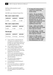
... modem or telephone wiring during an electrical storm. ❑ Do not use only No. 26 AWG or larger telecommunication line cord. iii VAIO Computer Reference Manual Safety Information and Caution CD-RW Laser Diode Properties Max. To change the backup battery, contact your desktop to the eyes, ...do not expose your nearest Sony Service Center. ! As the laser beam used in the vicinity of optical instruments with this product is specifically designed for wet locations. ...
... modem or telephone wiring during an electrical storm. ❑ Do not use only No. 26 AWG or larger telecommunication line cord. iii VAIO Computer Reference Manual Safety Information and Caution CD-RW Laser Diode Properties Max. To change the backup battery, contact your desktop to the eyes, ...do not expose your nearest Sony Service Center. ! As the laser beam used in the vicinity of optical instruments with this product is specifically designed for wet locations. ...
Reference Manual
Page 5
... equipment generates, uses, and can be shielded and grounded. You are designed to operate this equipment. v VAIO Computer Reference Manual Regulatory Information Declaration of FCC Rules. These limits are cautioned that any interference received, including interference...not expressly approved in this computer product. Operation is connected. ❑ Consult the dealer or an experienced radio/TV technician for a Class B digital device, pursuant to comply with Part 15 of Conformity Trade Name: SONY Model No.: PCV-L640 Responsible Party: Sony Electronics Inc. However, ...
... equipment generates, uses, and can be shielded and grounded. You are designed to operate this equipment. v VAIO Computer Reference Manual Regulatory Information Declaration of FCC Rules. These limits are cautioned that any interference received, including interference...not expressly approved in this computer product. Operation is connected. ❑ Consult the dealer or an experienced radio/TV technician for a Class B digital device, pursuant to comply with Part 15 of Conformity Trade Name: SONY Model No.: PCV-L640 Responsible Party: Sony Electronics Inc. However, ...
Reference Manual
Page 6
... or procedures that could affect the operations of the sending machine or such business, other electronic device to the Sony Customer Information Center, 12451 Gateway Blvd., Fort Myers, FL 33913. If trouble is experienced with this happens, ...Ringer Equivalence Number (REN) for this information into your facsimile, see your right to the telephone company. For the Sony Service Center nearest you, call . But if advance notice is 0.7. If requested, this equipment should not exceed five ... FCC if you believe it unlawful for any person to use a computer or other entity, or individual.
... or procedures that could affect the operations of the sending machine or such business, other electronic device to the Sony Customer Information Center, 12451 Gateway Blvd., Fort Myers, FL 33913. If trouble is experienced with this happens, ...Ringer Equivalence Number (REN) for this information into your facsimile, see your right to the telephone company. For the Sony Service Center nearest you, call . But if advance notice is 0.7. If requested, this equipment should not exceed five ... FCC if you believe it unlawful for any person to use a computer or other entity, or individual.
Reference Manual
Page 7
...température de plus de 100°C. Évacuer promptement la batterie us ées selon les directives du fabricant. ! vii VAIO Computer Reference Manual Telephone Consumer Guidelines (Canada) Please refer to the manufacturer's instructions. ! Une batterie non conforme présente un danger ...d'explosion. Discard used batteries according to your nearest Sony Service Center or Factory Service Center. ✍ In some areas the disposal of used in this device may be prohibited. Do ...
...température de plus de 100°C. Évacuer promptement la batterie us ées selon les directives du fabricant. ! vii VAIO Computer Reference Manual Telephone Consumer Guidelines (Canada) Please refer to the manufacturer's instructions. ! Une batterie non conforme présente un danger ...d'explosion. Discard used batteries according to your nearest Sony Service Center or Factory Service Center. ✍ In some areas the disposal of used in this device may be prohibited. Do ...

Reference Manual
Page 8
This certification means that compliance with the above conditions may give the telecommunications company cause to request that the sum of the Ringer Equivalence Numbers of the power utility, telephone lines and internal metallic water pipe system, if present, are connected together. The equipment must also be particularly important in rural areas. The customer should be coordinated by a representative designated by the user to this equipment may not prevent degradation of service in the appropriate Terminal Equipment Technical Requirements document(s). The Ringer Equivalence ...
This certification means that compliance with the above conditions may give the telecommunications company cause to request that the sum of the Ringer Equivalence Numbers of the power utility, telephone lines and internal metallic water pipe system, if present, are connected together. The equipment must also be particularly important in rural areas. The customer should be coordinated by a representative designated by the user to this equipment may not prevent degradation of service in the appropriate Terminal Equipment Technical Requirements document(s). The Ringer Equivalence ...
Reference Manual
Page 11
vi Telephone Consumer Guidelines (Canada vii DISPOSAL OF LITHIUM ION BATTERY vii INDUSTRY CANADA NOTICE viii AVIS DE L'INDUSTRIE CANADA viii Chapter 1 - Configuring Your System Accessing the CMOS Setup Utility 14 Changing the Display's Power Management Settings 15 Configuring the System Board 17 CMOS Jumper 17 CPU Frequency Ratio Multiplier Switches 19 AGP_INT Switch 20 VGA Switch 21 xi Identifying Components Front View 2 Drives 3 Buttons and Switches 4 Indicators 5 Connectors 6 Slots ...7 Rear View 8 I/O Connectors 9 Chapter 2 - Contents Notice to Users ii Safety ...
vi Telephone Consumer Guidelines (Canada vii DISPOSAL OF LITHIUM ION BATTERY vii INDUSTRY CANADA NOTICE viii AVIS DE L'INDUSTRIE CANADA viii Chapter 1 - Configuring Your System Accessing the CMOS Setup Utility 14 Changing the Display's Power Management Settings 15 Configuring the System Board 17 CMOS Jumper 17 CPU Frequency Ratio Multiplier Switches 19 AGP_INT Switch 20 VGA Switch 21 xi Identifying Components Front View 2 Drives 3 Buttons and Switches 4 Indicators 5 Connectors 6 Slots ...7 Rear View 8 I/O Connectors 9 Chapter 2 - Contents Notice to Users ii Safety ...
Reference Manual
Page 12
xii VAIO Slimtop™ Reference Manual Chapter 3 - Removing, Installing, and Replacing Components Removing the System Cover 24 Replacing the System Cover 25 Installing an Add-In Card 26 ... VGA MONITOR Connectors 57 LCD Connector 59 Wake On LAN (WOL_CON) Connector 60 LINE IN and LINE OUT Connectors 61 PHONE and MIC Connectors 62 Sony Memory Stick Slot Connector 63 i.LINK Interface Header Connectors 64 i.LINK Connectors 65 Auxiliary Audio In Connector 66 Configuration Jumper and Switches 67 CMOS Jumper...
xii VAIO Slimtop™ Reference Manual Chapter 3 - Removing, Installing, and Replacing Components Removing the System Cover 24 Replacing the System Cover 25 Installing an Add-In Card 26 ... VGA MONITOR Connectors 57 LCD Connector 59 Wake On LAN (WOL_CON) Connector 60 LINE IN and LINE OUT Connectors 61 PHONE and MIC Connectors 62 Sony Memory Stick Slot Connector 63 i.LINK Interface Header Connectors 64 i.LINK Connectors 65 Auxiliary Audio In Connector 66 Configuration Jumper and Switches 67 CMOS Jumper...
Reference Manual
Page 13
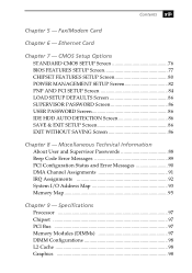
Ethernet Card Chapter 7 - CMOS Setup Options STANDARD CMOS SETUP Screen 76 BIOS FEATURES SETUP Screen 77 CHIPSET FEATURES SETUP Screen 80 POWER MANAGEMENT SETUP Screen 82 PNP AND PCI SETUP Screen 84 LOAD SETUP DEFAULTS Screen 86 SUPERVISOR PASSWORD Screen 86 USER PASSWORD Screen 86 IDE HDD AUTO DETECTION Screen 86 SAVE & EXIT SETUP Screen 86 EXIT WITHOUT SAVING Screen 86 Chapter 8 - Miscellaneous Technical Information About User and Supervisor Passwords 88 Beep Code Error Messages 89 PCI Configuration Status and Error Messages 90 DMA Channel Assignments 91 IRQ Assignments 92 ...
Ethernet Card Chapter 7 - CMOS Setup Options STANDARD CMOS SETUP Screen 76 BIOS FEATURES SETUP Screen 77 CHIPSET FEATURES SETUP Screen 80 POWER MANAGEMENT SETUP Screen 82 PNP AND PCI SETUP Screen 84 LOAD SETUP DEFAULTS Screen 86 SUPERVISOR PASSWORD Screen 86 USER PASSWORD Screen 86 IDE HDD AUTO DETECTION Screen 86 SAVE & EXIT SETUP Screen 86 EXIT WITHOUT SAVING Screen 86 Chapter 8 - Miscellaneous Technical Information About User and Supervisor Passwords 88 Beep Code Error Messages 89 PCI Configuration Status and Error Messages 90 DMA Channel Assignments 91 IRQ Assignments 92 ...
Reference Manual
Page 15
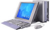
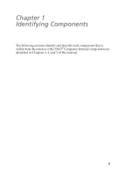
Internal components are identified in Chapters 3, 4, and 5 of the VAIO® Computer. Chapter 1 Identifying Components The following sections identify and describe each component that is visible from the exterior of this manual. 1
Internal components are identified in Chapters 3, 4, and 5 of the VAIO® Computer. Chapter 1 Identifying Components The following sections identify and describe each component that is visible from the exterior of this manual. 1

Reference Manual
Page 17
CD-R disc read : 14X (maximum performance). CD-RW disc read : 20X (maximum performance). The average data transfer rate is 14X (2100 kbytes/s). The average data transfer rate is 10X (1500 kbytes/s). CD-R disc write: 4X (maximum performance). CD-RW disc write: 4X (maximum performance). * The CD-RW/CD-R/CD-ROM data transfer standard 1X rate is read at a variable transfer rate, ranging from 6X at the innermost track to 20X at the outermost track. Data on a CD-RW/CD-R is written at a constant transfer rate of 2X or 4X, depending on a CD-RW is read : 20X (maximum performance). ...
CD-R disc read : 14X (maximum performance). CD-RW disc read : 20X (maximum performance). The average data transfer rate is 14X (2100 kbytes/s). The average data transfer rate is 10X (1500 kbytes/s). CD-R disc write: 4X (maximum performance). CD-RW disc write: 4X (maximum performance). * The CD-RW/CD-R/CD-ROM data transfer standard 1X rate is read at a variable transfer rate, ranging from 6X at the innermost track to 20X at the outermost track. Data on a CD-RW/CD-R is written at a constant transfer rate of 2X or 4X, depending on a CD-RW is read : 20X (maximum performance). ...
Reference Manual
Page 18
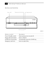
Ejects an optical disc. Ejects a diskette. Automatically opens the CD-RW tray. SHA0003.VSD 4 VAIO Slimtop™ Reference Manual Buttons and Switches Power on/off Manual eject hole Floppy disk eject FD DISC HD CD-RW disc eject Button or switch Power/Standby switch Floppy disk eject button CD-RW disc eject button Emergency eject hole Description Turns system power on and off.
Ejects an optical disc. Ejects a diskette. Automatically opens the CD-RW tray. SHA0003.VSD 4 VAIO Slimtop™ Reference Manual Buttons and Switches Power on/off Manual eject hole Floppy disk eject FD DISC HD CD-RW disc eject Button or switch Power/Standby switch Floppy disk eject button CD-RW disc eject button Emergency eject hole Description Turns system power on and off.

Reference Manual
Page 19
... SHA0004.VSD Indicator Power/Standby indicator Diskette drive access indicator CD-RW drive access indicator Hard disk drive access indicator Description Standby (amber) indicates the computer is in standby mode. On (green) indicates diskette drive activity. On (amber) indicates optical disc activity. On (green) indicates hard disk drive activity. Off (no...
... SHA0004.VSD Indicator Power/Standby indicator Diskette drive access indicator CD-RW drive access indicator Hard disk drive access indicator Description Standby (amber) indicates the computer is in standby mode. On (green) indicates diskette drive activity. On (amber) indicates optical disc activity. On (green) indicates hard disk drive activity. Off (no...
Reference Manual
Page 20
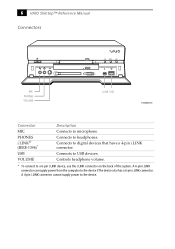
... if the device also has a 6-pin i.LINK connector. A 6-pin i.LINK connector can supply power from the computer to a 6-pin i.LINK device, use the i.LINK connector on the back of the system. Connects to microphone. 6 VAIO Slimtop™ Reference Manual Connectors FD DISC HD MIC PHONES VOLUME i.LINK USB SHA0005.VSD Connector MIC PHONES...
... if the device also has a 6-pin i.LINK connector. A 6-pin i.LINK connector can supply power from the computer to a 6-pin i.LINK device, use the i.LINK connector on the back of the system. Connects to microphone. 6 VAIO Slimtop™ Reference Manual Connectors FD DISC HD MIC PHONES VOLUME i.LINK USB SHA0005.VSD Connector MIC PHONES...
Reference Manual
Page 21
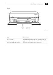
Accommodates Memory Stick media. Slots Identifying Components 7 FD DISC HD PC Card Slot Memory Stick Media Slot SHA0006.VSD Slot PC Card Slot Memory Stick® Media Slot Description Accommodates one Type I or Type II PCMCIA card.
Accommodates Memory Stick media. Slots Identifying Components 7 FD DISC HD PC Card Slot Memory Stick Media Slot SHA0006.VSD Slot PC Card Slot Memory Stick® Media Slot Description Accommodates one Type I or Type II PCMCIA card.
Reference Manual
Page 22
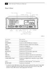
...computer to output connector on audio device. Connects to parallel device. Connects to a 6-pin i.LINK device, use the i.LINK connector on the back of the system. Connects to the device if the device also has a 6-pin i.LINK connector. Connects to keyboard. * To connect to VAIO Slimtop... connector. Connects to RJ-45 Ethernet connector. A 6-pin i.LINK connector can supply power from wall jack. Connects to telephone. 8 VAIO Slimtop™ Reference Manual Rear View Power LINE ETHERNET PHONE PRINTER SERIAL MONITOR LINE USB LINE IN OUT I.LINK S400 LCD PHONE KEYBOARD PRINTER ...
...computer to output connector on audio device. Connects to parallel device. Connects to a 6-pin i.LINK device, use the i.LINK connector on the back of the system. Connects to the device if the device also has a 6-pin i.LINK connector. Connects to keyboard. * To connect to VAIO Slimtop... connector. Connects to RJ-45 Ethernet connector. A 6-pin i.LINK connector can supply power from wall jack. Connects to telephone. 8 VAIO Slimtop™ Reference Manual Rear View Power LINE ETHERNET PHONE PRINTER SERIAL MONITOR LINE USB LINE IN OUT I.LINK S400 LCD PHONE KEYBOARD PRINTER ...

Reference Manual
Page 23
SHA0009.VSD PRINTER Port The PRINTER port is a standard 25-pin DB-25 female connector assigned as LPT1. 13 1 25 14 KY0005.VSD SERIAL Port The SERIAL port is a standard 9-pin DB-9 male connector assigned as COM1. 1 5 6 9 KY0057.VSD MONITOR The MONITOR connector is a standard 15-pin female high-density VGAtype connector. Identifying Components 9 I/O Connectors The following section identifies the various I/O connectors.
SHA0009.VSD PRINTER Port The PRINTER port is a standard 25-pin DB-25 female connector assigned as LPT1. 13 1 25 14 KY0005.VSD SERIAL Port The SERIAL port is a standard 9-pin DB-9 male connector assigned as COM1. 1 5 6 9 KY0057.VSD MONITOR The MONITOR connector is a standard 15-pin female high-density VGAtype connector. Identifying Components 9 I/O Connectors The following section identifies the various I/O connectors.
Reference Manual
Page 24
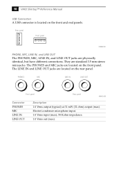
...). The LINE IN and LINE OUT jacks are located on the rear panel. The PHONES and MIC jacks are located on the front panel. 10 VAIO Slimtop™ Reference Manual USB Connectors A USB connector is located on the front and real panels.
...). The LINE IN and LINE OUT jacks are located on the rear panel. The PHONES and MIC jacks are located on the front panel. 10 VAIO Slimtop™ Reference Manual USB Connectors A USB connector is located on the front and real panels.
Reference Manual
Page 25
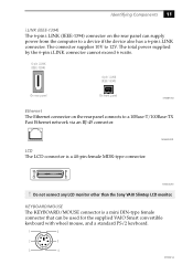
Do not connect any LCD monitor other than the Sony VAIO Slimtop LCD monitor. The total power supplied by the 6-pin i.LINK connector... panel On front panel KY0087.VSD Ethernet The Ethernet connector on the rear panel can be used for the supplied VAIO Smart convertible keyboard with wheel mouse, and a standard PS/2 keyboard. 1 6 2 5 3 4 KY0002.VS... LCD The LCD connector is a mini DIN-type female connector that can supply power from the computer to a device if the device also has a 6-pin i.LINK connector. MAN009.VSD KY0004.VSD ! The connector supplies 10V...
Do not connect any LCD monitor other than the Sony VAIO Slimtop LCD monitor. The total power supplied by the 6-pin i.LINK connector... panel On front panel KY0087.VSD Ethernet The Ethernet connector on the rear panel can be used for the supplied VAIO Smart convertible keyboard with wheel mouse, and a standard PS/2 keyboard. 1 6 2 5 3 4 KY0002.VS... LCD The LCD connector is a mini DIN-type female connector that can supply power from the computer to a device if the device also has a 6-pin i.LINK connector. MAN009.VSD KY0004.VSD ! The connector supplies 10V...
Reference Manual
Page 26
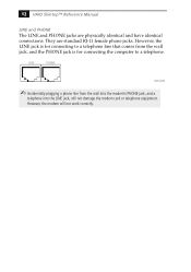
However, the modem will not damage the modem card or telephone equipment. However, the LINE jack is for connecting to a telephone line that comes from the wall into the modem's PHONE jack, and a telephone into the LINE jack, will not work correctly. They are physically identical and have identical connections. 12 VAIO Slimtop™ Reference Manual LINE and PHONE The LINE and PHONE jacks are standard RJ-11 female phone jacks. LINE PHONE KY0014.VSD ✍ Accidentally plugging a phone line from the wall jack, and the PHONE jack is for connecting the computer to a telephone.
However, the modem will not damage the modem card or telephone equipment. However, the LINE jack is for connecting to a telephone line that comes from the wall into the modem's PHONE jack, and a telephone into the LINE jack, will not work correctly. They are physically identical and have identical connections. 12 VAIO Slimtop™ Reference Manual LINE and PHONE The LINE and PHONE jacks are standard RJ-11 female phone jacks. LINE PHONE KY0014.VSD ✍ Accidentally plugging a phone line from the wall jack, and the PHONE jack is for connecting the computer to a telephone.