Integration Guide
Page 1
HD VISUAL COMMUNICATION SYSTEM PCS-XG80 PCS-XG80S PCS-XG55 PCS-XG55S SYSTEM INTEGRATION MANUAL 1st Edition (Revised 1) Version 2.0 and Later (PCS-XG80) Version 2.1 and Later (PCS-XG55)
HD VISUAL COMMUNICATION SYSTEM PCS-XG80 PCS-XG80S PCS-XG55 PCS-XG55S SYSTEM INTEGRATION MANUAL 1st Edition (Revised 1) Version 2.0 and Later (PCS-XG80) Version 2.1 and Later (PCS-XG55)
Integration Guide
Page 3
... by Using Service Menu 3-8 3-1-4. Confirmation Procedure of Two Networks (PCS-XG80/ XG80S only 2-12 PCS-XG80 1 Network Trouble Check 3-27 3-7-1. System Connections 1-26 1-2-1. PCS-XG Series Models Connection Using SIP... 1-27 1-2-3. IPv6 1-30 1-2-6. Firmware Update...19 3-5-1. Operation Log 3-25 3-6-4. Peripheral Status 3-18 3-5. Turning On the System 2-1 2-1-2. Difference between PCS-XG80/XG80S and PCS-XG55/ XG55S 1-42 2. Test Procedure 3-27 3-7-2. Description on Service Menu 3-20 3-6. Other Setup 2-6 2-3. Table of Your First Time Power...
... by Using Service Menu 3-8 3-1-4. Confirmation Procedure of Two Networks (PCS-XG80/ XG80S only 2-12 PCS-XG80 1 Network Trouble Check 3-27 3-7-1. System Connections 1-26 1-2-1. PCS-XG Series Models Connection Using SIP... 1-27 1-2-3. IPv6 1-30 1-2-6. Firmware Update...19 3-5-1. Operation Log 3-25 3-6-4. Peripheral Status 3-18 3-5. Turning On the System 2-1 2-1-2. Difference between PCS-XG80/XG80S and PCS-XG55/ XG55S 1-42 2. Test Procedure 3-27 3-7-2. Description on Service Menu 3-20 3-6. Other Setup 2-6 2-3. Table of Your First Time Power...
Integration Guide
Page 5
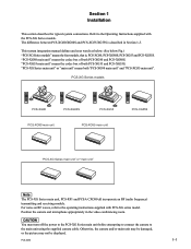
... unit" means the codec box of both PCS-XG55 and PCS-XG55S. PCS-XG80 1-1 "PCS-XG Series main unit" or "main unit" means both PCS-XG80 and PCS-XG80S. PCS-XG Series models / T W PCS-XG80 / T W PCS-XG80S / T W PCS-XG55 PCS-XG80 main unit PCS-XG55 main unit / T W PCS-XG55S "PCS-XG Series main unit" or "main unit" n The PCS-XG Series main unit, PCS-RF1 and PCSA-CXG80 all incorporate an...
... unit" means the codec box of both PCS-XG55 and PCS-XG55S. PCS-XG80 1-1 "PCS-XG Series main unit" or "main unit" means both PCS-XG80 and PCS-XG80S. PCS-XG Series models / T W PCS-XG80 / T W PCS-XG80S / T W PCS-XG55 PCS-XG80 main unit PCS-XG55 main unit / T W PCS-XG55S "PCS-XG Series main unit" or "main unit" n The PCS-XG Series main unit, PCS-RF1 and PCSA-CXG80 all incorporate an...

Integration Guide
Page 7
... by making a "simple connection", connect the cables to the connector on the PCS-XG55 main unit. PCS-XG80 1-3 Simple Connection Making a "simple connection" To start video conferencing by the shading, are not available on the PCS-XG55 main unit. * The 1 connector on the PCS-XG80 main unit corresponds to the green connectors, as shown below. 2 Supplied... camera cable. 3 Connect the microphones. 4 Connect the network cable. 5 Connect the AC power adaptor. 1-1. to 1* 5 Supplied Not supplied 4 Not supplied to LAN Connector caps for PCS-XG Series Models 1-1-1.
... by making a "simple connection", connect the cables to the connector on the PCS-XG55 main unit. PCS-XG80 1-3 Simple Connection Making a "simple connection" To start video conferencing by the shading, are not available on the PCS-XG55 main unit. * The 1 connector on the PCS-XG80 main unit corresponds to the green connectors, as shown below. 2 Supplied... camera cable. 3 Connect the microphones. 4 Connect the network cable. 5 Connect the AC power adaptor. 1-1. to 1* 5 Supplied Not supplied 4 Not supplied to LAN Connector caps for PCS-XG Series Models 1-1-1.
Integration Guide
Page 11
... connected to the operating instructions supplied with the PCS-XG Series models. PCS-XG80 1-7 This function is separately required. (For detail, contact your local Sony Sales Office/Service Center.) Breakout cable EVI-HD1 Shell 1 2 3 4 5 9 1 6 7 8 9 15 8 10 to PCS-XG Series 11 main unit 12 13 14 ...-HD1 Shell * The S VIDEO IN, EC-MIC (A7) 1/2, AUDIO 1 IN, EXT 1/2, and 2 connectors are not available on the PCS-XG55 main unit. The 1 connector on the PCS-XG55 main unit. As the 1st camera, PCSA-CXG80, PCSA-CG70, EVI-HD1, BRC-H700/Z700. As the 2nd camera, EVI-HD1, BRC...
... connected to the operating instructions supplied with the PCS-XG Series models. PCS-XG80 1-7 This function is separately required. (For detail, contact your local Sony Sales Office/Service Center.) Breakout cable EVI-HD1 Shell 1 2 3 4 5 9 1 6 7 8 9 15 8 10 to PCS-XG Series 11 main unit 12 13 14 ...-HD1 Shell * The S VIDEO IN, EC-MIC (A7) 1/2, AUDIO 1 IN, EXT 1/2, and 2 connectors are not available on the PCS-XG55 main unit. The 1 connector on the PCS-XG55 main unit. As the 1st camera, PCSA-CXG80, PCSA-CG70, EVI-HD1, BRC-H700/Z700. As the 2nd camera, EVI-HD1, BRC...
Integration Guide
Page 12
... OUT HDMI OUT 1-EXT-2 ISDN UNIT 1 AUX CONTROL DC 19.5V 2 Breakout cable is separately required. (For detail, contact your local Sony Sales Office/Service Center.) Breakout cable BRC-H700 PCS-XG Series main unit rear panel* CAMERA EC-MIC(A7) 12 S VIDEO IN MIC(A1/A3) 1(R) 2(L) RGB IN RGB OUT (PLUG... OUT EXT SYNC IN VIDEO S VIDEO DC IN 12V * The S VIDEO IN, EC-MIC (A7) 1/2, AUDIO 1 IN, EXT 1/2, and 2 connectors are not available on the PCS-XG55 main unit. 1-8 PCS-XG80 When using a camera other than the PCSA-CXG80, do not set "RF Remote Control Reception" to the connector on the...
... OUT HDMI OUT 1-EXT-2 ISDN UNIT 1 AUX CONTROL DC 19.5V 2 Breakout cable is separately required. (For detail, contact your local Sony Sales Office/Service Center.) Breakout cable BRC-H700 PCS-XG Series main unit rear panel* CAMERA EC-MIC(A7) 12 S VIDEO IN MIC(A1/A3) 1(R) 2(L) RGB IN RGB OUT (PLUG... OUT EXT SYNC IN VIDEO S VIDEO DC IN 12V * The S VIDEO IN, EC-MIC (A7) 1/2, AUDIO 1 IN, EXT 1/2, and 2 connectors are not available on the PCS-XG55 main unit. 1-8 PCS-XG80 When using a camera other than the PCSA-CXG80, do not set "RF Remote Control Reception" to the connector on the...

Integration Guide
Page 16
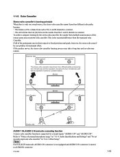
...from the loud speaker. For details on placing the PCSA-A7 microphones . PCS-XG55/XG55S can not be a problem. Position the PCSA-A7 microphone at least 1.5 m (5 ft.) from the participants. . Otherwise echo is likely to be used. . PCSA-A7 PCS-XG80/XG80S 1.5 m Loud speaker n Notes on the cascade layout and the... power supply of the PCSA-A7, refer to the layout shown below. PCSA-A7 microphone layout (PCS-XG80/XG80S only) Be particularly careful when setting up the ...
...from the loud speaker. For details on placing the PCSA-A7 microphones . PCS-XG55/XG55S can not be a problem. Position the PCSA-A7 microphone at least 1.5 m (5 ft.) from the participants. . Otherwise echo is likely to be used. . PCSA-A7 PCS-XG80/XG80S 1.5 m Loud speaker n Notes on the cascade layout and the... power supply of the PCSA-A7, refer to the layout shown below. PCSA-A7 microphone layout (PCS-XG80/XG80S only) Be particularly careful when setting up the ...

Integration Guide
Page 17
...AUX CONTROL DC 19.5V 2 1 2 3 4 5 *1 The S VIDEO IN, EC-MIC (A7) 1/2, AUDIO 1 IN, EXT 1/2, and 2 connectors are not available on PCS-XG55 main unit. PCS-XG Series main unit front panel*2 / LAN 1 ALERT LAN 2 ALERT OPEN VIDEO IN Y Pb Pr AUDIO 2 IN L R 6 OPEN MAINTENANCE *2 The LAN 2 ALERT LED... on PCS-XG80 main unit is labeled ON LINE LED on PCS-XG55 main unit, and AUDIO 2 IN is labeled AUDIO IN. The 1 connector on the PCS-XG80 main unit corresponds to the connector on the PCS-XG55 main unit. No. Connector name Type 1 EC-MIC (A7...
...AUX CONTROL DC 19.5V 2 1 2 3 4 5 *1 The S VIDEO IN, EC-MIC (A7) 1/2, AUDIO 1 IN, EXT 1/2, and 2 connectors are not available on PCS-XG55 main unit. PCS-XG Series main unit front panel*2 / LAN 1 ALERT LAN 2 ALERT OPEN VIDEO IN Y Pb Pr AUDIO 2 IN L R 6 OPEN MAINTENANCE *2 The LAN 2 ALERT LED... on PCS-XG80 main unit is labeled ON LINE LED on PCS-XG55 main unit, and AUDIO 2 IN is labeled AUDIO IN. The 1 connector on the PCS-XG80 main unit corresponds to the connector on the PCS-XG55 main unit. No. Connector name Type 1 EC-MIC (A7...
Integration Guide
Page 18
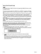
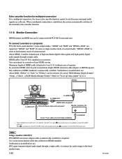
... thus produce an unexpected sound. n Do not activate the TV's surround sound feature as it may prevent the echo canceller of external microphone usage n For PCS-XG55 main unit, AUDIO 1 IN connector is not equipped and AUDIO 2 IN connector is limited.). To display the volume meter, confirm its output level... with "AUDIO 1 IN" or "AUDIO 2 IN", you can be inputted to the appropriate level, and do not adjust the volume on the TV monitor. 1-14 PCS-XG80
... thus produce an unexpected sound. n Do not activate the TV's surround sound feature as it may prevent the echo canceller of external microphone usage n For PCS-XG55 main unit, AUDIO 1 IN connector is not equipped and AUDIO 2 IN connector is limited.). To display the volume meter, confirm its output level... with "AUDIO 1 IN" or "AUDIO 2 IN", you can be inputted to the appropriate level, and do not adjust the volume on the TV monitor. 1-14 PCS-XG80

Integration Guide
Page 21
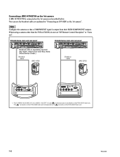
...A R B MIC (A1/A3), L AUDIO 1 IN, AUDIO 2 IN R Loud Speaker R L Camera L Loud Speaker Sender side L R Reversed Receiver side PCS-XG Series main unit Transmitting PCS-XG Series main unit L R Loud Speaker L Monitor A B Loud Speaker R n For PCS-XG55 main unit, AUDIO 1 IN connector is not equipped and AUDIO 2 IN connector is "Off ".) You cannot use reversed... you to select whether to transmit the audio input from the microphone with right and left can be used with AUDIO 1 IN/AUDIO 2 IN (PCS-XG80 main unit), or AUDIO IN (PCS-XG55 main unit) when these inputs are used for MIC.
...A R B MIC (A1/A3), L AUDIO 1 IN, AUDIO 2 IN R Loud Speaker R L Camera L Loud Speaker Sender side L R Reversed Receiver side PCS-XG Series main unit Transmitting PCS-XG Series main unit L R Loud Speaker L Monitor A B Loud Speaker R n For PCS-XG55 main unit, AUDIO 1 IN connector is not equipped and AUDIO 2 IN connector is "Off ".) You cannot use reversed... you to select whether to transmit the audio input from the microphone with right and left can be used with AUDIO 1 IN/AUDIO 2 IN (PCS-XG80 main unit), or AUDIO IN (PCS-XG55 main unit) when these inputs are used for MIC.

Integration Guide
Page 22
Right and left not reversed (Setting of "Audio Input" = AUX) R L AUDIO 1 IN, AUDIO 2 IN R Loud Speaker R L Camera L Loud Speaker Sender side Receiver side Not reversed R L PCS-XG Series main unit Transmitting PCS-XG Series main unit R L Loud Speaker R Monitor A B Loud Speaker L n For PCS-XG55 main unit, AUDIO 1 IN connector is not equipped and AUDIO 2 IN connector is named to AUDIO IN connector. 1-18 PCS-XG80
Right and left not reversed (Setting of "Audio Input" = AUX) R L AUDIO 1 IN, AUDIO 2 IN R Loud Speaker R L Camera L Loud Speaker Sender side Receiver side Not reversed R L PCS-XG Series main unit Transmitting PCS-XG Series main unit R L Loud Speaker R Monitor A B Loud Speaker L n For PCS-XG55 main unit, AUDIO 1 IN connector is not equipped and AUDIO 2 IN connector is named to AUDIO IN connector. 1-18 PCS-XG80
Integration Guide
Page 23
... 1-1-5. The arrival time interval (Δt) between the sounds from the L and R channels is the essential difference from the monaural echo Canceller. PCS-XG80 1-19 Monitor Loud Speaker Loud Speaker Monitor Loud Speaker Loud Speaker Microphone L Microphone R Δt Sender side AUDIO 1 IN, AUDIO 2... IN and echo canceling function A stereo echo canceller function is constant. . n For PCS-XG55 main unit, AUDIO 1 IN connector is not equipped and AUDIO 2 IN connector is only one sound source, the stereo echo canceller cannot learn ...
... 1-1-5. The arrival time interval (Δt) between the sounds from the L and R channels is the essential difference from the monaural echo Canceller. PCS-XG80 1-19 Monitor Loud Speaker Loud Speaker Monitor Loud Speaker Loud Speaker Microphone L Microphone R Δt Sender side AUDIO 1 IN, AUDIO 2... IN and echo canceling function A stereo echo canceller function is constant. . n For PCS-XG55 main unit, AUDIO 1 IN connector is not equipped and AUDIO 2 IN connector is only one sound source, the stereo echo canceller cannot learn ...
Integration Guide
Page 24
...unit has 3 video output modes. Verification is established, the system automatically switches to the connector on the PCS-XG55 main unit. Refer to the loudspeaker input. 1-20 PCS-XG80 When a multipoint connection is needed before use . "HDMI" and "RGB" are supported. You can connect... connection For a multipoint connection, the stereo echo canceller function cannot be used because monaural audio signals are not available on the PCS-XG55 main unit. Maximum length of HDMI cable is required. Monitor VISCA OUT TERMINAL to HDMI OUT to HDMI IN CAMERA EC-MIC...
...unit has 3 video output modes. Verification is established, the system automatically switches to the connector on the PCS-XG55 main unit. Refer to the loudspeaker input. 1-20 PCS-XG80 When a multipoint connection is needed before use . "HDMI" and "RGB" are supported. You can connect... connection For a multipoint connection, the stereo echo canceller function cannot be used because monaural audio signals are not available on the PCS-XG55 main unit. Maximum length of HDMI cable is required. Monitor VISCA OUT TERMINAL to HDMI OUT to HDMI IN CAMERA EC-MIC...
Integration Guide
Page 25
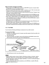
...to use the function of the main unit before use it must have a 1080i INPUT connection. To connect a Pen Tablet 1. To TABLET connector (PCS-XG80 main unit)/ OPTION connector (PCS-XG55 main unit) 1.5 m (5 ft.) supplied cable with "Bamboo" (MTE-450) or cable connected with "Bamboo" (MTE450) is 1.5 m (5 ... to the TABLET connector (PCS-XG80 main unit)/OPTION connector (PCS- About the pen tablet, refer to turn on the RGB monitor. If you use . So, prepare a pen tablet separately. XG55 main unit) on the rear of the Communication System and sending an external control ...
...to use the function of the main unit before use it must have a 1080i INPUT connection. To connect a Pen Tablet 1. To TABLET connector (PCS-XG80 main unit)/ OPTION connector (PCS-XG55 main unit) 1.5 m (5 ft.) supplied cable with "Bamboo" (MTE-450) or cable connected with "Bamboo" (MTE450) is 1.5 m (5 ... to the TABLET connector (PCS-XG80 main unit)/OPTION connector (PCS- About the pen tablet, refer to turn on the RGB monitor. If you use . So, prepare a pen tablet separately. XG55 main unit) on the rear of the Communication System and sending an external control ...
Integration Guide
Page 28
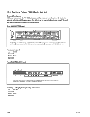
... Pb Pr AUDIO 2 IN L R OPEN MAINTENANCE The LAN 2 ALERT LED on PCS-XG80 main unit is labeled ON LINE LED on PCS-XG55 main unit, and AUDIO 2 IN is labeled AUDIO IN on the rear and is on PCS-XG55 main unit. Parity: None . The other is for maintenance. bps: 38400 .... For taking a debug log/For engineering maintenance . Data bit: 8 . Two Serial Ports on the PCS-XG55 main unit. Stop bit: 1 1-24 PCS-XG80 Data bit: 8 . Rear: AUX CONTROL port CAMERA EC-MIC(A7) 12 S VIDEO IN MIC(A1/A3) 1(R) 2(L) RGB IN RGB OUT ...
... Pb Pr AUDIO 2 IN L R OPEN MAINTENANCE The LAN 2 ALERT LED on PCS-XG80 main unit is labeled ON LINE LED on PCS-XG55 main unit, and AUDIO 2 IN is labeled AUDIO IN on the rear and is on PCS-XG55 main unit. Parity: None . The other is for maintenance. bps: 38400 .... For taking a debug log/For engineering maintenance . Data bit: 8 . Two Serial Ports on the PCS-XG55 main unit. Stop bit: 1 1-24 PCS-XG80 Data bit: 8 . Rear: AUX CONTROL port CAMERA EC-MIC(A7) 12 S VIDEO IN MIC(A1/A3) 1(R) 2(L) RGB IN RGB OUT ...

Integration Guide
Page 30
... cable (category 5, straight) (not supplied) *1 The S VIDEO IN, EC-MIC (A7) 1/2, AUDIO 1 IN, EXT 1/2, and 2 connectors are not available on the PCS-XG55 main unit. *2 The 1 connector on the PCSXG80 main unit corresponds to automatically upgrade the software of the main unit is being used with the power... on the PCS-XG55 main unit. Do not connect/disconnect the camera cable, interface cable, or pen tablet with a Camera Unit or ISDN Unit for the fi...
... cable (category 5, straight) (not supplied) *1 The S VIDEO IN, EC-MIC (A7) 1/2, AUDIO 1 IN, EXT 1/2, and 2 connectors are not available on the PCS-XG55 main unit. *2 The 1 connector on the PCSXG80 main unit corresponds to automatically upgrade the software of the main unit is being used with the power... on the PCS-XG55 main unit. Do not connect/disconnect the camera cable, interface cable, or pen tablet with a Camera Unit or ISDN Unit for the fi...

Integration Guide
Page 31
... to a SIP server through the 2 (LAN2) connector is shown as a standard function. 1 (LAN1) connector on PCS-XG80/XG80S or (LAN) connector on PCS-XG55/XG55S is not supported. m . Multi server support Multi call id support P2P AV communication NEC SIP Telephone terminal support Internal ... is not available. . This is used during regular communication. . PCS-XG55 includes one PCS-A1, and PCS-XG80S/XG55S includes no PCS-A1. 1-2-2. Connection to make an audio recording of this connection, the two microphones PCS-A1 are displayed, but is supported as below. The SIP function of...
... to a SIP server through the 2 (LAN2) connector is shown as a standard function. 1 (LAN1) connector on PCS-XG80/XG80S or (LAN) connector on PCS-XG55/XG55S is not supported. m . Multi server support Multi call id support P2P AV communication NEC SIP Telephone terminal support Internal ... is not available. . This is used during regular communication. . PCS-XG55 includes one PCS-A1, and PCS-XG80S/XG55S includes no PCS-A1. 1-2-2. Connection to make an audio recording of this connection, the two microphones PCS-A1 are displayed, but is supported as below. The SIP function of...

Integration Guide
Page 32
...(supplied) TV monitor (not supplied) to the connector on the PCS-XG55 main unit. In this connection, the two microphones PCS-A1 are displayed, but two PCS-A1s are not available on the PCS-XG80 main unit corresponds to a wall outlet * The S VIDEO... IN, EC-MIC (A7) 1/2, AUDIO 1 IN, EXT 1/2, and 2 connectors are supplied only with PCS-XG80. The 1 connector on the PCS-XG55 main unit. PCS-XG55 includes one PCS-A1, and PCS-XG80S/XG55S includes no PCS-A1. 1-28 PCS...
...(supplied) TV monitor (not supplied) to the connector on the PCS-XG55 main unit. In this connection, the two microphones PCS-A1 are displayed, but two PCS-A1s are not available on the PCS-XG80 main unit corresponds to a wall outlet * The S VIDEO... IN, EC-MIC (A7) 1/2, AUDIO 1 IN, EXT 1/2, and 2 connectors are supplied only with PCS-XG80. The 1 connector on the PCS-XG55 main unit. PCS-XG55 includes one PCS-A1, and PCS-XG80S/XG55S includes no PCS-A1. 1-28 PCS...

Integration Guide
Page 34
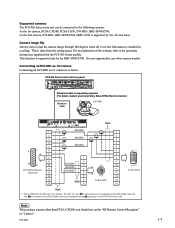
...and/or ISDN line. The PCSA-MCG80 HD MCU software allows you to establish multipoint HD visual communication with the PCS-XG Series models. Multipoint Connection (Example of the system are restricted as follows when using Internet Protocol IPv6. ...only) To enable multipoint HD visual communication, you cannot use IPv6. LAN2 n When "Line I/F → Use LAN2" is disabled (it cannot be installed in PCS-XG55/XG55S. IPv6 This equipment supports the next-generation Internet Protocol version 6 (IPv6). System configuration 2 POWER/STANDBY 5 POWER/STANDBY / 1 3 / T W...
...and/or ISDN line. The PCSA-MCG80 HD MCU software allows you to establish multipoint HD visual communication with the PCS-XG Series models. Multipoint Connection (Example of the system are restricted as follows when using Internet Protocol IPv6. ...only) To enable multipoint HD visual communication, you cannot use IPv6. LAN2 n When "Line I/F → Use LAN2" is disabled (it cannot be installed in PCS-XG55/XG55S. IPv6 This equipment supports the next-generation Internet Protocol version 6 (IPv6). System configuration 2 POWER/STANDBY 5 POWER/STANDBY / 1 3 / T W...

Integration Guide
Page 35
... 6 POWER/STANDBY / POWER/STANDBY / POWER/STANDBY / POWER/STANDBY / POWER/STANDBY / 4 1 PCS-XG80S HD Visual Communication System 2 PCSA-CXG80 HD Camera Unit 3 PCS-RF1 Remote Commander 4 TV monitor (not supplied) 5 PCS-A1 microphone 6 HD MCU software PCSA-MCG80 (Option) 7 ISDN unit PCSA-B384S (Option) or ...PCS-XG80 1-31 System configuration via an ISDN for multipoint (Main terminal: PCS-XG80/XG80S only) You need to connect the optional PCSA-B384S or PCSA-B768S ISDN Unit especially designed for use with this system and to six sites over ISDN. n It cannot be installed in PCS-XG55/XG55S...
... 6 POWER/STANDBY / POWER/STANDBY / POWER/STANDBY / POWER/STANDBY / POWER/STANDBY / 4 1 PCS-XG80S HD Visual Communication System 2 PCSA-CXG80 HD Camera Unit 3 PCS-RF1 Remote Commander 4 TV monitor (not supplied) 5 PCS-A1 microphone 6 HD MCU software PCSA-MCG80 (Option) 7 ISDN unit PCSA-B384S (Option) or ...PCS-XG80 1-31 System configuration via an ISDN for multipoint (Main terminal: PCS-XG80/XG80S only) You need to connect the optional PCSA-B384S or PCSA-B768S ISDN Unit especially designed for use with this system and to six sites over ISDN. n It cannot be installed in PCS-XG55/XG55S...


