
Operating Instructions
Page 18
... can transfer audio data from the computer to the recorder or audio data that you to transfer non-audio data such as an external drive, allowing you have recorded on the recorder or another MD component to the computer. The battery should be possible. When using a Macintosh... enables you to transfer audio data between the computer and the recorder The supplied SonicStage software allows you to record a CD in the computer's CD drive directly to a disc in the recorder. For detailed explanations, refer to SonicStage Help. • Record directly from • the computer's speakers when...
... can transfer audio data from the computer to the recorder or audio data that you to transfer non-audio data such as an external drive, allowing you have recorded on the recorder or another MD component to the computer. The battery should be possible. When using a Macintosh... enables you to transfer audio data between the computer and the recorder The supplied SonicStage software allows you to record a CD in the computer's CD drive directly to a disc in the recorder. For detailed explanations, refer to SonicStage Help. • Record directly from • the computer's speakers when...

Operating Instructions
Page 19
... IBM PC/AT or Compatible • CPU: Pentium III 450 MHz or higher • Hard disk drive space: 200 MB or more (1.5 GB or more Others • CD drive (capable of digital playback by operating systems other than those listed above, custom-built PCs, operating systems ...only with a computer Installing the SonicStage/MD Simple Burner software System requirements The following system environment is not supported by WDM) (A CD-R/RW drive is necessary for CD writing) • Sound Board • USB port Operating System Factory installed: Windows XP Media Center Edition 2005/Windows...
... IBM PC/AT or Compatible • CPU: Pentium III 450 MHz or higher • Hard disk drive space: 200 MB or more (1.5 GB or more Others • CD drive (capable of digital playback by operating systems other than those listed above, custom-built PCs, operating systems ...only with a computer Installing the SonicStage/MD Simple Burner software System requirements The following system environment is not supported by WDM) (A CD-R/RW drive is necessary for CD writing) • Sound Board • USB port Operating System Factory installed: Windows XP Media Center Edition 2005/Windows...

Operating Instructions
Page 20
... 2000/Windows XP) • Virus-check software is activated. (Such software demands a large amount of system resources.) 2 Insert the supplied CD-ROM into the CD drive of your system environment.
... 2000/Windows XP) • Virus-check software is activated. (Such software demands a large amount of system resources.) 2 Insert the supplied CD-ROM into the CD drive of your system environment.
Operating Instructions
Page 23
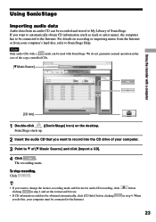
When 23 We do this, your computer. 3 Point to of your computer must be connected to record into the CD drive of [ Music Source] and click [Import a CD]. 4 Click . The recording starts. To stop recording. Click . • If you want to automatically obtain CD ...
When 23 We do this, your computer. 3 Point to of your computer must be connected to record into the CD drive of [ Music Source] and click [Import a CD]. 4 Click . The recording starts. To stop recording. Click . • If you want to automatically obtain CD ...

Operating Instructions
Page 27
Recording using the recorder operations (Simple mode) 1 Insert a disc into the CD drive of your computer to the recorder without storing the data to the computer's hard disk. You can select the setting when the CDDB has more ... Simple Burner icon in standard mode or OpenMG software (SonicStage, OpenMG Jukebox, etc.) is active. 27 We do not guarantee normal operation in the CD drive of your computer. 3 Press and slide REC on the recorder. Before starting recording, you can be used with a computer Using MD Simple Burner MD...
Recording using the recorder operations (Simple mode) 1 Insert a disc into the CD drive of your computer to the recorder without storing the data to the computer's hard disk. You can select the setting when the CDDB has more ... Simple Burner icon in standard mode or OpenMG software (SonicStage, OpenMG Jukebox, etc.) is active. 27 We do not guarantee normal operation in the CD drive of your computer. 3 Press and slide REC on the recorder. Before starting recording, you can be used with a computer Using MD Simple Burner MD...
Operating Instructions
Page 28
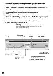
... Net MD: LP2/LP4 Hi-MD: PCM/Hi-SP/Hi-LP/48 kbps 28 Recording by computer operations (Standard mode) 1 Insert a disc into the CD drive of your computer ( page 21). 2 Double-click ([MD Simple Burner] icon) on the desktop. You can operate MD Simple Burner from the following two...
... Net MD: LP2/LP4 Hi-MD: PCM/Hi-SP/Hi-LP/48 kbps 28 Recording by computer operations (Standard mode) 1 Insert a disc into the CD drive of your computer ( page 21). 2 Double-click ([MD Simple Burner] icon) on the desktop. You can operate MD Simple Burner from the following two...
Operating Instructions
Page 29
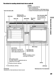
... menu [Close] To close the display as shown on audio CD to do the following: - The window for MD Simple Burner - Set the CD-ROM drive - To select all tracks, click here. CD operating section Use these controls to confirm the tracks on page 28, click here.
... menu [Close] To close the display as shown on audio CD to do the following: - The window for MD Simple Burner - Set the CD-ROM drive - To select all tracks, click here. CD operating section Use these controls to confirm the tracks on page 28, click here.

Operating Instructions
Page 64
...do not operate the recorder. You are using the recorder at a place with vibration. You need 200 MB or more , depending on your CD drive or system environment. The recorder is recognized by USB bus power. Insert Audio CD. The capacity of a transferred track is not enough hard... take 30 minutes or more free space on your hard disk. Check for a few minutes during the installation. This is still in CD drive of an error message beneath the installation window. Press the [Alt] key or [Tab] key to have stopped before it does not operate normally. ...
...do not operate the recorder. You are using the recorder at a place with vibration. You need 200 MB or more , depending on your CD drive or system environment. The recorder is recognized by USB bus power. Insert Audio CD. The capacity of a transferred track is not enough hard... take 30 minutes or more free space on your hard disk. Check for a few minutes during the installation. This is still in CD drive of an error message beneath the installation window. Press the [Alt] key or [Tab] key to have stopped before it does not operate normally. ...

Operating Instructions
Page 77
... remove dirt. • Dust on the rechargeable battery with a cotton swab or a soft cloth as it may lead to play . Do not use earphones while driving, cycling, or operating any type of battery fluid or bursting battery. Additional Information 77 On the earphones Road safety Do not use any motorized...
... remove dirt. • Dust on the rechargeable battery with a cotton swab or a soft cloth as it may lead to play . Do not use earphones while driving, cycling, or operating any type of battery fluid or bursting battery. Additional Information 77 On the earphones Road safety Do not use any motorized...

Brochure
Page 2
MZ-RH1 Hi-MD Field Recorder Features Large Main Unit LCD Display Displays ... title transfer time is perfect for tracks that are backward compatible with conversion to enhance your PC's hard drive. Playback is not available when USB is just getting into a music management application where you can store...19 Hours1 Battery Life With rechargeable battery when playing in ATRAC3plus @ 48kbps. 4. Features and specifications are trademarks of Sony. Up to 100x Transfer Speed5 Transfer your music directly from independent artists. Specifications General Data Transfer Rate: Up to...
MZ-RH1 Hi-MD Field Recorder Features Large Main Unit LCD Display Displays ... title transfer time is perfect for tracks that are backward compatible with conversion to enhance your PC's hard drive. Playback is not available when USB is just getting into a music management application where you can store...19 Hours1 Battery Life With rechargeable battery when playing in ATRAC3plus @ 48kbps. 4. Features and specifications are trademarks of Sony. Up to 100x Transfer Speed5 Transfer your music directly from independent artists. Specifications General Data Transfer Rate: Up to...
Service Manual
Page 4
...System requirements The following system environment is required in order to electrostatic break-down because of the potential difference generated by WDM) (A CD-R/RW drive is necessary for CD writing) • Sound Board • USB port Operating System Factory installed: Windows XP Media Center Edition 2005/Windows ... system requirements. • The NTFS format of IC401, IC501, IC601 and IC701 on the OLED board can not be exchanged alone. MZ-RH1 SECTION 1 SERVICING NOTES NOTES ON HANDLING THE OPTICAL PICK-UP BLOCK OR BASE UNIT The laser diode in the optical pick-up block ...
...System requirements The following system environment is required in order to electrostatic break-down because of the potential difference generated by WDM) (A CD-R/RW drive is necessary for CD writing) • Sound Board • USB port Operating System Factory installed: Windows XP Media Center Edition 2005/Windows ... system requirements. • The NTFS format of IC401, IC501, IC601 and IC701 on the OLED board can not be exchanged alone. MZ-RH1 SECTION 1 SERVICING NOTES NOTES ON HANDLING THE OPTICAL PICK-UP BLOCK OR BASE UNIT The laser diode in the optical pick-up block ...
Service Manual
Page 13
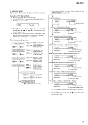
... switching > key x key [VOL +] key: 100th place of item number increase. [VOL --] key: 100th place of the set by function. Minor item switching > key: . MZ-RH1 3. MANUAL MODE This is written. 5. key is pressed for several seconds respectively. 4. To release the Manual mode, press the x key to return to activate the...*1) XXXX ***B## item number adjusted value CEMAX value • ADIP Error Value & Adjusted Value Display XXXX ***B## item number adjusted value ADIP error value • Focus Drive Value & Adjusted Value Display XXXX ***B## item number adjusted value focus...
... switching > key x key [VOL +] key: 100th place of item number increase. [VOL --] key: 100th place of the set by function. Minor item switching > key: . MZ-RH1 3. MANUAL MODE This is written. 5. key is pressed for several seconds respectively. 4. To release the Manual mode, press the x key to return to activate the...*1) XXXX ***B## item number adjusted value CEMAX value • ADIP Error Value & Adjusted Value Display XXXX ***B## item number adjusted value ADIP error value • Focus Drive Value & Adjusted Value Display XXXX ***B## item number adjusted value focus...

Service Manual
Page 21
... MDVCC PVCC VCC MDVCC REGO2 REGO3 MZ-RH1 • SIGNAL PATH : PLAYBACK : REC OVER WRITE HEAD DRIVE Q681, 682 BUFFER IC681 3A 11 1A 2 4A 14 9 3Y 4 1Y 12 4Y 7 2Y 2A 5 DRIVE SELECT IC682 3B 10 1B 3 XG...) U V M701 W (SPINDLE) U V TO IC801 (2/3) (AUDIO SECTION) SYSTEM CONTROLLER, DSP IC801 (1/3) FOCUS/TRACKING COIL DRIVE, SPINDLE/SLED MOTOR DRIVE IC701 TRK+ TRK- HR601 OVER WRITE HEAD VREF IY IX JX JY A B C D F OPTICAL IIN PICK-UP BLOCK ...SPCV 152 SPCW 153 CLV_MON_U CLV_MON_V CLV_MON_W MZ-RH1 FCS+ FCS- LD CONTROL Q503 FCS+ FCS- SECTION 6 DIAGRAMS 6-1.
... MDVCC PVCC VCC MDVCC REGO2 REGO3 MZ-RH1 • SIGNAL PATH : PLAYBACK : REC OVER WRITE HEAD DRIVE Q681, 682 BUFFER IC681 3A 11 1A 2 4A 14 9 3Y 4 1Y 12 4Y 7 2Y 2A 5 DRIVE SELECT IC682 3B 10 1B 3 XG...) U V M701 W (SPINDLE) U V TO IC801 (2/3) (AUDIO SECTION) SYSTEM CONTROLLER, DSP IC801 (1/3) FOCUS/TRACKING COIL DRIVE, SPINDLE/SLED MOTOR DRIVE IC701 TRK+ TRK- HR601 OVER WRITE HEAD VREF IY IX JX JY A B C D F OPTICAL IIN PICK-UP BLOCK ...SPCV 152 SPCW 153 CLV_MON_U CLV_MON_V CLV_MON_W MZ-RH1 FCS+ FCS- LD CONTROL Q503 FCS+ FCS- SECTION 6 DIAGRAMS 6-1.

Service Manual
Page 22
... 290 291 276 277 CS_RTC 189 SI0 178 SO0 179 SCK0 180 XCS_NV 220 PROTECT HIMD_PROTECT XHOLD_SW OPEN_CLOSE_SW HALF_LOCK_SW 132 119 120 261 202 LED DRIVE Q475 S1 - 8 (PANEL KEYS) D2 (REC) 134 131 171 172 127 OFF HOLD S462 HALF LOCK S463 OPEN/CLOSE DETECT S461 PROTECT DETECT S465 Hi... 62 XCS 55 /RESET 45 X1 4MHz 37 OEC3 38 OSC4 RESET SWITCH Q471 250 SI4 251 SO4 252 SCK4 254 XCS_DISPLAY 268 XRST_DISPLAY VC1 MZ-RH1 OLED_VCC VDD (DISPLAY) DC/DC CONVERTER IC472, Q472 B+ SWITCH Q473, 474 +2.5V REGULATOR IC471 VB 305 EL_PWR_CTL 253 EL_VDD_CTL 123 208 WAKE UP DETECT Q901...
... 290 291 276 277 CS_RTC 189 SI0 178 SO0 179 SCK0 180 XCS_NV 220 PROTECT HIMD_PROTECT XHOLD_SW OPEN_CLOSE_SW HALF_LOCK_SW 132 119 120 261 202 LED DRIVE Q475 S1 - 8 (PANEL KEYS) D2 (REC) 134 131 171 172 127 OFF HOLD S462 HALF LOCK S463 OPEN/CLOSE DETECT S461 PROTECT DETECT S465 Hi... 62 XCS 55 /RESET 45 X1 4MHz 37 OEC3 38 OSC4 RESET SWITCH Q471 250 SI4 251 SO4 252 SCK4 254 XCS_DISPLAY 268 XRST_DISPLAY VC1 MZ-RH1 OLED_VCC VDD (DISPLAY) DC/DC CONVERTER IC472, Q472 B+ SWITCH Q473, 474 +2.5V REGULATOR IC471 VB 305 EL_PWR_CTL 253 EL_VDD_CTL 123 208 WAKE UP DETECT Q901...

Service Manual
Page 25
MAIN Section (1/7) - • See page 36 for IC Block Diagrams. MZ-RH1 SLD_PWM SLD_CON_W SLD_CON_V SLD_CON_U CLV_MON_W CLV_MON_V CLV_MON_U CLVN (1/7) SLEDU SLEDV SLEDW CL743 CL742 CL741 CL740 CL739... 0 CPUI2 CPVI2 CPWI2 COM2 CPUO2 CPVO2 CPWO2 FI1 RI1 FO1 RO1 FI2 RI2 FO2 RO2 NC FOCUS/TRACKING COIL DRIVE, SPINDLE/SLED MOTOR DRIVE IC701 BD6608GLV-E2 ∗ CSP (Chip Size Package) CPUI1 WO1 VO1 UO1 PWM1 WI1 VI1 UI1 ST2 ST1 ...0.1 C510 0.1 C513 4700p R503 2.2k R504 4.7k CL527 C514 1000p C515 10p RFI VIN (Page 28) (Page 30) (Page 26) MZ-RH1 25 25 6-4. SCHEMATIC DIAGRAM -
MAIN Section (1/7) - • See page 36 for IC Block Diagrams. MZ-RH1 SLD_PWM SLD_CON_W SLD_CON_V SLD_CON_U CLV_MON_W CLV_MON_V CLV_MON_U CLVN (1/7) SLEDU SLEDV SLEDW CL743 CL742 CL741 CL740 CL739... 0 CPUI2 CPVI2 CPWI2 COM2 CPUO2 CPVO2 CPWO2 FI1 RI1 FO1 RO1 FI2 RI2 FO2 RO2 NC FOCUS/TRACKING COIL DRIVE, SPINDLE/SLED MOTOR DRIVE IC701 BD6608GLV-E2 ∗ CSP (Chip Size Package) CPUI1 WO1 VO1 UO1 PWM1 WI1 VI1 UI1 ST2 ST1 ...0.1 C510 0.1 C513 4700p R503 2.2k R504 4.7k CL527 C514 1000p C515 10p RFI VIN (Page 28) (Page 30) (Page 26) MZ-RH1 25 25 6-4. SCHEMATIC DIAGRAM -

Service Manual
Page 26
MZ-RH1 MZ-RH1 6-5. SCHEMATIC DIAGRAM - MAIN Section (2/7) - • See page 36 for IC Block Diagrams. (2/7) ...MA22D1700LS0 C691 100p CL601 (VREC) TP601 C685 10 6.3V -1 CL681 -2 S Q681 CPH5614-TL-E Q681,682 OVER WRITE HEAD DRIVE FB683 FB684 FB685 FB686 CL683 C690 100p FB692 C686 0.1 BUFFER IC681 SN74LVC541ARGYR O7 O6 O5 O4 O3 O2 O1 O0 XOE2 ... B+ SWITCH S S L601 10µH C615 10 10V C616 1 C617 47 6.3V CL603 CL602 C618 0.01 OVER WRITE HEAD DRIVE, POWER CONTROL IC601 SC901585VAR2 ∗ CSP(Chip Size Package) CL607 C621 0.01 D10 (Page 30) 26 26 NC_A1 DW_1B DW_1T...
MZ-RH1 MZ-RH1 6-5. SCHEMATIC DIAGRAM - MAIN Section (2/7) - • See page 36 for IC Block Diagrams. (2/7) ...MA22D1700LS0 C691 100p CL601 (VREC) TP601 C685 10 6.3V -1 CL681 -2 S Q681 CPH5614-TL-E Q681,682 OVER WRITE HEAD DRIVE FB683 FB684 FB685 FB686 CL683 C690 100p FB692 C686 0.1 BUFFER IC681 SN74LVC541ARGYR O7 O6 O5 O4 O3 O2 O1 O0 XOE2 ... B+ SWITCH S S L601 10µH C615 10 10V C616 1 C617 47 6.3V CL603 CL602 C618 0.01 OVER WRITE HEAD DRIVE, POWER CONTROL IC601 SC901585VAR2 ∗ CSP(Chip Size Package) CL607 C621 0.01 D10 (Page 30) 26 26 NC_A1 DW_1B DW_1T...

Service Manual
Page 31
SCHEMATIC DIAGRAM - 6-10. MAIN Section (7/7) - • See page 24 for Waveforms. • See page 36 for IC Block Diagrams. MZ-RH1 REG5_TSBY REG5_REG LED_RED (7/7) (Page 35) CN471 18P NC NC LED_RED SET_KEY_2 SET_KEY_1 REC SDO(OLED-LCD_SI) SDI(OLED-LCD_SO) SCK XCS XRST XWK PAUSE ... CL482 CL481 CL480 CL479 CL478 CL477 CL476 R472 4.7k TP471 TP472 TP473 R471 4.7k R493 1k R473 4.7k D471 HRC0201ATRF-E CL490 Q475 RT1N144U-TP-1 LED DRIVE R475 100 R474 100 R476 100 CL474 CL472 C4481 0.1 -1-2 Q471 RT2C00M-TP RESET SWITCH R478 220k C471 0.1 R490 47k C473 1 SGND (Page 29) C474 2.2...
SCHEMATIC DIAGRAM - 6-10. MAIN Section (7/7) - • See page 24 for Waveforms. • See page 36 for IC Block Diagrams. MZ-RH1 REG5_TSBY REG5_REG LED_RED (7/7) (Page 35) CN471 18P NC NC LED_RED SET_KEY_2 SET_KEY_1 REC SDO(OLED-LCD_SI) SDI(OLED-LCD_SO) SCK XCS XRST XWK PAUSE ... CL482 CL481 CL480 CL479 CL478 CL477 CL476 R472 4.7k TP471 TP472 TP473 R471 4.7k R493 1k R473 4.7k D471 HRC0201ATRF-E CL490 Q475 RT1N144U-TP-1 LED DRIVE R475 100 R474 100 R476 100 CL474 CL472 C4481 0.1 -1-2 Q471 RT2C00M-TP RESET SWITCH R478 220k C471 0.1 R490 47k C473 1 SGND (Page 29) C474 2.2...

Service Manual
Page 41
MZ-RH1 NC RO2 FO2 RI2 FI2 RO1 FO1 RI1 FI1 CPWO2 CPVO2 CPUO2 COM2 CPWI2 CPVI2 CPUI2 IC701 BD6608GLV-E2 64 63 62 61 60 59 58 57 56 55 54 53 52 51 50 49 + − + − + − PGNDUV1 1 PGNDW1 2 PGNDUV2 3 PGNDUV2 4 PGNDW2 5 PGNDW2 6 PGND1 7 PGND2 8 GND 9 PRE DRIVE PRE DRIVE PRE DRIVE DRIVER... DECODER 48 WO2 47 WO2 46 VO2 45 VO2 44 UO2 43 UO2 42 PWM2 41 WI2 40 VI2 39 UI2 DECODER PRE DRIVE VMU1 10 VMVW1 11 VMU2 12 VMU2 13 VMVW2 14 VMVW2 15 VMF1 16 STANDBY 17 18 19 20 21 22 23 24 25 26 ...
MZ-RH1 NC RO2 FO2 RI2 FI2 RO1 FO1 RI1 FI1 CPWO2 CPVO2 CPUO2 COM2 CPWI2 CPVI2 CPUI2 IC701 BD6608GLV-E2 64 63 62 61 60 59 58 57 56 55 54 53 52 51 50 49 + − + − + − PGNDUV1 1 PGNDW1 2 PGNDUV2 3 PGNDUV2 4 PGNDW2 5 PGNDW2 6 PGND1 7 PGND2 8 GND 9 PRE DRIVE PRE DRIVE PRE DRIVE DRIVER... DECODER 48 WO2 47 WO2 46 VO2 45 VO2 44 UO2 43 UO2 42 PWM2 41 WI2 40 VI2 39 UI2 DECODER PRE DRIVE VMU1 10 VMVW1 11 VMU2 12 VMU2 13 VMVW2 14 VMVW2 15 VMF1 16 STANDBY 17 18 19 20 21 22 23 24 25 26 ...

Service Manual
Page 46
... over write head driver and power control IC 146 SLVS O Sled servo drive PWM signal output to the motor driver 147 SPDU O Spindle motor drive control signal output (U) to the motor driver 148 SPVS O Spindle servo drive PWM signal output to the motor driver 149 SPDV O Spindle motor...(for internal D-RAM power supply information keeping 129 JOG_A I Jog dial pulse input terminal (A phase) Not used 130 JOG_B I Spindle motor drive comparison signal input (V) from the motor driver 152 SPCV I Jog dial pulse input terminal (B phase) Not used 114 ADC1EXTC - MZ-RH1 Pin No.
... over write head driver and power control IC 146 SLVS O Sled servo drive PWM signal output to the motor driver 147 SPDU O Spindle motor drive control signal output (U) to the motor driver 148 SPVS O Spindle servo drive PWM signal output to the motor driver 149 SPDV O Spindle motor...(for internal D-RAM power supply information keeping 129 JOG_A I Jog dial pulse input terminal (A phase) Not used 130 JOG_B I Spindle motor drive comparison signal input (V) from the motor driver 152 SPCV I Jog dial pulse input terminal (B phase) Not used 114 ADC1EXTC - MZ-RH1 Pin No.

Service Manual
Page 47
... XI_SENSE O Current limit circuit control signal output terminal when adapter is used 166 OFTRK I Reset signal input from the motor driver 159 SLDU O Sled motor drive control signal output (U) to the motor driver 160 FS256OUT O 11.2896 MHz clock output to the RF amplifier 161 CHOPPERCLK O Clock signal output for chopper... output terminal for current detection amplifier to MNT6 O Monitor output terminal for DSP Not used 204 XRST2_DET I /O Tracking signal input/output for MD3 167 NC - MZ-RH1 Pin No.
... XI_SENSE O Current limit circuit control signal output terminal when adapter is used 166 OFTRK I Reset signal input from the motor driver 159 SLDU O Sled motor drive control signal output (U) to the motor driver 160 FS256OUT O 11.2896 MHz clock output to the RF amplifier 161 CHOPPERCLK O Clock signal output for chopper... output terminal for current detection amplifier to MNT6 O Monitor output terminal for DSP Not used 204 XRST2_DET I /O Tracking signal input/output for MD3 167 NC - MZ-RH1 Pin No.

