Operating Instructions
Page 2
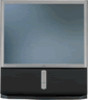
...television receiver for other outlet unless the blades can be determined by turning the equipment off and on a circuit different from the broadcaster/cable company and/or program owner. Record these numbers in the literature accompanying the appliance. As an ENERGY STAR Partner, Sony... RM-Y902 MODELS: KP-53HS10, KP-61HS10 Please keep the brightness and contrast functions at the rear of Contents and Remote Control Graphics REFER SERVICING TO QUALIFIED SERVICE PERSONNEL. This symbol is connected. • Consult the dealer or an experienced radio/TV technician for help. ...
...television receiver for other outlet unless the blades can be determined by turning the equipment off and on a circuit different from the broadcaster/cable company and/or program owner. Record these numbers in the literature accompanying the appliance. As an ENERGY STAR Partner, Sony... RM-Y902 MODELS: KP-53HS10, KP-61HS10 Please keep the brightness and contrast functions at the rear of Contents and Remote Control Graphics REFER SERVICING TO QUALIFIED SERVICE PERSONNEL. This symbol is connected. • Consult the dealer or an experienced radio/TV technician for help. ...
Operating Instructions
Page 3
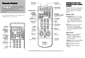
... PICTURE MODE FREEZE SWAP POSITION GUIDE CC ZOOM IN LEFT RIGHT ACTIVE DISPLAY TV/VIDEO ANT 123 456 7 JUMP VOL 89 ENTER 0 MENU CH RESET TV POWER (pages 25, 55) FUNCTION (pages 25, 55) PIP/P&P/ CHANNEL INDEX (pages 28 - 32) TV/VIDEO (page 26) ANT (page 25) 0-9 buttons (page 25) ENTER (...; Remote Control In the instructions that follow, we will refer to power operations, like turning the projection TV, DBS/CABLE, or VTR (VCR)/MDP/DVD Player on or off Label color White:TV/VTR (VCR)/MDP/ DVD Player/DBS (Direct Broadcast Satellite)/CABLE operation buttons Yellow:PIP, P&P, and CHANNEL...
... PICTURE MODE FREEZE SWAP POSITION GUIDE CC ZOOM IN LEFT RIGHT ACTIVE DISPLAY TV/VIDEO ANT 123 456 7 JUMP VOL 89 ENTER 0 MENU CH RESET TV POWER (pages 25, 55) FUNCTION (pages 25, 55) PIP/P&P/ CHANNEL INDEX (pages 28 - 32) TV/VIDEO (page 26) ANT (page 25) 0-9 buttons (page 25) ENTER (...; Remote Control In the instructions that follow, we will refer to power operations, like turning the projection TV, DBS/CABLE, or VTR (VCR)/MDP/DVD Player on or off Label color White:TV/VTR (VCR)/MDP/ DVD Player/DBS (Direct Broadcast Satellite)/CABLE operation buttons Yellow:PIP, P&P, and CHANNEL...

Operating Instructions
Page 4
...Cable or an Antenna 7 Connecting a Cable Box 8 Connecting an Antenna/Cable TV System to a VCR 9 Connecting a VCR and Projection TV to a Cable Box 10 Connecting a DTV (Digital Television) Receiver 11 Connecting a DBS (Direct Broadcast Satellite) Receiver 13 Connecting a ...DBS (Direct Broadcast Satellite) Receiver and VCR 14 Connecting a Camcorder 15 Connecting Two VCRs for Tape Editing 16 Connecting a DVD Player With S Video or Composite Video...
...Cable or an Antenna 7 Connecting a Cable Box 8 Connecting an Antenna/Cable TV System to a VCR 9 Connecting a VCR and Projection TV to a Cable Box 10 Connecting a DTV (Digital Television) Receiver 11 Connecting a DBS (Direct Broadcast Satellite) Receiver 13 Connecting a ...DBS (Direct Broadcast Satellite) Receiver and VCR 14 Connecting a Camcorder 15 Connecting Two VCRs for Tape Editing 16 Connecting a DVD Player With S Video or Composite Video...

Operating Instructions
Page 5
... ; Model KP-53HS10 is for models KP-53HS10 and KP-61HS10. FAVORITE CHANNEL, allowing you to view and choose from eight of SRS Labs, Inc. in Canada 51 Additional Operations Operating Video Equipment 53 Setting the Manufacturer's Code . . . . 53 Operating video equipment 54 Operating... conventional NTSC picture. (not available for purchasing the Sony Color Rear Video Projection TV. Picture-in function (Twin View™) - By using the VIDEO 5 (DTV) IN jacks, you can connect a DTV (digital television) receiver to view DTV programs. The VIDEO 5 (DTV) IN jacks also function as R/...
... ; Model KP-53HS10 is for models KP-53HS10 and KP-61HS10. FAVORITE CHANNEL, allowing you to view and choose from eight of SRS Labs, Inc. in Canada 51 Additional Operations Operating Video Equipment 53 Setting the Manufacturer's Code . . . . 53 Operating video equipment 54 Operating... conventional NTSC picture. (not available for purchasing the Sony Color Rear Video Projection TV. Picture-in function (Twin View™) - By using the VIDEO 5 (DTV) IN jacks, you can connect a DTV (digital television) receiver to view DTV programs. The VIDEO 5 (DTV) IN jacks also function as R/...
Operating Instructions
Page 6
...slightly dampened with solution of mild soap and warm water. Instructions in this manual are written for cleaning. Precautions Safety • Operate the projection TV only on 120 V AC. • The plug is designed, for several days, disconnect the power by qualified service personnel before turning on... a cold to a warm location, or if the room temperature changes suddenly, the picture may be blurred or show poor color. Never pull on page 3. Note on the projection TV. • To obtain the best picture, do not block the ventilation openings. • Do not install the projection...
...slightly dampened with solution of mild soap and warm water. Instructions in this manual are written for cleaning. Precautions Safety • Operate the projection TV only on 120 V AC. • The plug is designed, for several days, disconnect the power by qualified service personnel before turning on... a cold to a warm location, or if the room temperature changes suddenly, the picture may be blurred or show poor color. Never pull on page 3. Note on the projection TV. • To obtain the best picture, do not block the ventilation openings. • Do not install the projection...

Operating Instructions
Page 8
... cart combination should not be located in the vicinity of overhead power lines or other electric light or power circuits, or where it from a projection TV set on a bed, sofa, rug or other materials. - Section 810 of the National Electrical Code (NEC) in USA and Section 54 of the ... a bookcase, or built-in a wet basement or near or over the power cord, and do not place the set , and to provide some projection TV sets to the set may cause the appliance and cart combination to grounding electrodes, and requirements for the grounding electrode. Ventilation The slots and openings...
... cart combination should not be located in the vicinity of overhead power lines or other electric light or power circuits, or where it from a projection TV set on a bed, sofa, rug or other materials. - Section 810 of the National Electrical Code (NEC) in USA and Section 54 of the ... a bookcase, or built-in a wet basement or near or over the power cord, and do not place the set , and to provide some projection TV sets to the set may cause the appliance and cart combination to grounding electrodes, and requirements for the grounding electrode. Ventilation The slots and openings...

Operating Instructions
Page 10
... three or more people. Blue PR (CR, Cr or R-Y) - Coaxial cable Standard TV cable and antenna cable Plug Type Push into connection. S Video cable High quality video cable for easy movement on Type Screw into connection. Video - Please move your projection TV using the casters. White Audio (Right) - Red Some DVD Players are equipped with...
... three or more people. Blue PR (CR, Cr or R-Y) - Coaxial cable Standard TV cable and antenna cable Plug Type Push into connection. S Video cable High quality video cable for easy movement on Type Screw into connection. Video - Please move your projection TV using the casters. White Audio (Right) - Red Some DVD Players are equipped with...

Operating Instructions
Page 11
Black CONTROL S cable Sony cable for a DTV receiver Push into connection. older homes will probably have 300-ohm twin lead cable (see C). Installing and Connecting the Projection TV Composite video cable for CONTROL S connections. Blue R/PR - CONTROL S IN OUT CONTROL S IN OUT AUX IN OUT VIDEO 4 VIDEO 5 (DTV) SELECT IN VIDEO 1 VIDEO 3 HD VD S VIDEO VIDEO L (MONO) AUDIO R Y Y/G L PB PB...
Black CONTROL S cable Sony cable for a DTV receiver Push into connection. older homes will probably have 300-ohm twin lead cable (see C). Installing and Connecting the Projection TV Composite video cable for CONTROL S connections. Blue R/PR - CONTROL S IN OUT CONTROL S IN OUT AUX IN OUT VIDEO 4 VIDEO 5 (DTV) SELECT IN VIDEO 1 VIDEO 3 HD VD S VIDEO VIDEO L (MONO) AUDIO R Y Y/G L PB PB...

Operating Instructions
Page 12
..."CHANNEL FIX" on page 38) Select Cable or ANT mode by pressing ANT on your remote control. HBO, SHOWTIME, etc.) *cable box (Rear of projection TV) VHF/UHF and EAC-66 U/V mixer (not supplied) • UHF 300-ohm twin lead cable Cable or antenna This is made directly from... use scrambled or encoded signals that you are connecting a cable box through your Sony remote control to the projection TV. Connection is the simplest connection. CATV cable (Rear of projection TV) VHF/UHF Cable and antenna You may be able to program your cable box), and normal (CATV) channels by...
..."CHANNEL FIX" on page 38) Select Cable or ANT mode by pressing ANT on your remote control. HBO, SHOWTIME, etc.) *cable box (Rear of projection TV) VHF/UHF and EAC-66 U/V mixer (not supplied) • UHF 300-ohm twin lead cable Cable or antenna This is made directly from... use scrambled or encoded signals that you are connecting a cable box through your Sony remote control to the projection TV. Connection is the simplest connection. CATV cable (Rear of projection TV) VHF/UHF Cable and antenna You may be able to program your cable box), and normal (CATV) channels by...

Operating Instructions
Page 13
... LINE OUT S VIDEO VHF/UHF OUT IN 1 Cable/ Antenna VMC-810S/820S (not supplied) 3 YC-15V/30V (not supplied) 9 Disconnect all power sources before making any connections. S VIDEO (Rear of the S VIDEO cable. Note: • If you are connecting a monaural VCR, connect only the single audio output to AUDIO and S VIDEO IN on the projection TV.
... LINE OUT S VIDEO VHF/UHF OUT IN 1 Cable/ Antenna VMC-810S/820S (not supplied) 3 YC-15V/30V (not supplied) 9 Disconnect all power sources before making any connections. S VIDEO (Rear of the S VIDEO cable. Note: • If you are connecting a monaural VCR, connect only the single audio output to AUDIO and S VIDEO IN on the projection TV.
Operating Instructions
Page 14
... a coaxial cable, connect OUT on the cable box to IN on the VCR. 3 Using AUDIO and S VIDEO* cables, connect AUDIO and S VIDEO OUT on the VCR to by pressing TV/VIDEO. S VIDEO Disconnect all power sources before making any connections. (Rear of the S VIDEO cable. Note: • To view scrambled channels through the cable box, select the...
... a coaxial cable, connect OUT on the cable box to IN on the VCR. 3 Using AUDIO and S VIDEO* cables, connect AUDIO and S VIDEO OUT on the VCR to by pressing TV/VIDEO. S VIDEO Disconnect all power sources before making any connections. (Rear of the S VIDEO cable. Note: • To view scrambled channels through the cable box, select the...

Operating Instructions
Page 15
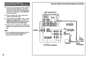
Installing and Connecting the Projection TV Connecting a DTV (Digital Television) Receiver Before connecting, be sure to read the Operating Instructions of VIDEO 5 (DTV) IN on the projection TV (WhiteAUDIO Left, Red-AUDIO Right). 4 Select VIDEO 5 by the TV/VIDEO button. 5 Select the SET UP menu and set DTV INPUT ... making any connections. 2 Composite video cable for DTV receiver, connect G, B, R, HD and VD of VIDEO OUT on the projection TV. If the DTV receiver is equipped with the Y/PB/ PR jacks, proceed to step 2 in "Connecting a DTV (digital television) receiver with the G/B/R/ HD/VD...
Installing and Connecting the Projection TV Connecting a DTV (Digital Television) Receiver Before connecting, be sure to read the Operating Instructions of VIDEO 5 (DTV) IN on the projection TV (WhiteAUDIO Left, Red-AUDIO Right). 4 Select VIDEO 5 by the TV/VIDEO button. 5 Select the SET UP menu and set DTV INPUT ... making any connections. 2 Composite video cable for DTV receiver, connect G, B, R, HD and VD of VIDEO OUT on the projection TV. If the DTV receiver is equipped with the Y/PB/ PR jacks, proceed to step 2 in "Connecting a DTV (digital television) receiver with the G/B/R/ HD/VD...

Operating Instructions
Page 16
... a DTV (digital television) receiver with the Y/PB/ PR (component video input) jacks 1 Attach the coaxial cable from the roof antenna to VHF/UHF on the DTV receiver. 2 Using three VIDEO cables, connect Y, PB and PR of COMPONENT VIDEO OUT on the DTV receiver to Y, PB and PR of VIDEO 5 (DTV) IN on the projection TV. 3 Using...
... a DTV (digital television) receiver with the Y/PB/ PR (component video input) jacks 1 Attach the coaxial cable from the roof antenna to VHF/UHF on the DTV receiver. 2 Using three VIDEO cables, connect Y, PB and PR of COMPONENT VIDEO OUT on the DTV receiver to Y, PB and PR of VIDEO 5 (DTV) IN on the projection TV. 3 Using...

Operating Instructions
Page 17
... before making any connections. (Rear of projection TV) CONTROL S IN OUT AUX IN OUT VIDEO 4 VIDEO 5 (DTV) SELECT IN VIDEO 1 VIDEO 3 HD VD Cable/ Satellite antenna Antenna cable 21 S VIDEO VIDEO L (MONO) AUDIO R Y Y/G L PB PB/B (MONO) PR PR/R R COMPONENT AUDIO S-VIDEO AUDIO-L AUDIO-R VHF/UHF VIDEO L AUDIO R SATELLITE IN LINE OUT DBS VHF/UHF AUDIO R AUDIO L VIDEO S VIDEO IN OUT RK-74A...
... before making any connections. (Rear of projection TV) CONTROL S IN OUT AUX IN OUT VIDEO 4 VIDEO 5 (DTV) SELECT IN VIDEO 1 VIDEO 3 HD VD Cable/ Satellite antenna Antenna cable 21 S VIDEO VIDEO L (MONO) AUDIO R Y Y/G L PB PB/B (MONO) PR PR/R R COMPONENT AUDIO S-VIDEO AUDIO-L AUDIO-R VHF/UHF VIDEO L AUDIO R SATELLITE IN LINE OUT DBS VHF/UHF AUDIO R AUDIO L VIDEO S VIDEO IN OUT RK-74A...

Operating Instructions
Page 18
...VIDEO (Rear of the S VIDEO cable. Connecting a DBS (Direct Broadcast Satellite) Receiver and VCR 1 Connect the cable from the satellite antenna to the satellite receiver. 2 Attach the coaxial cable from the DBS or VCR, select the video input which your VCR or DBS receiver is connected to AUDIO and S VIDEO... S VIDEO, use a VIDEO cable (yellow) instead of projection TV) CONTROL S IN OUT AUX IN OUT VIDEO 4 VIDEO 5 (DTV) SELECT IN VIDEO 1 VIDEO 3 HD VD Coaxial cable (not supplied) 3 SATELLITE IN LINE OUT VHF/UHF AUDIO R AUDIO L VIDEO S VIDEO IN OUT DBS S VIDEO VIDEO L ...
...VIDEO (Rear of the S VIDEO cable. Connecting a DBS (Direct Broadcast Satellite) Receiver and VCR 1 Connect the cable from the satellite antenna to the satellite receiver. 2 Attach the coaxial cable from the DBS or VCR, select the video input which your VCR or DBS receiver is connected to AUDIO and S VIDEO... S VIDEO, use a VIDEO cable (yellow) instead of projection TV) CONTROL S IN OUT AUX IN OUT VIDEO 4 VIDEO 5 (DTV) SELECT IN VIDEO 1 VIDEO 3 HD VD Coaxial cable (not supplied) 3 SATELLITE IN LINE OUT VHF/UHF AUDIO R AUDIO L VIDEO S VIDEO IN OUT DBS S VIDEO VIDEO L ...

Operating Instructions
Page 19
... a camcorder. * If your camcorder is not equipped with S VIDEO, use a VIDEO cable (yellow) instead of projection TV) S VIDEO Push to the left (MONO) input on the projection TV (WhiteAUDIO Left, Red-AUDIO Right**). 2 Press VIDEO 2 to select the video inputs from your camcorder. 1 Using AUDIO and S VIDEO* cables, connect AUDIO and S VIDEO OUT on the camcorder to AUDIO and...
... a camcorder. * If your camcorder is not equipped with S VIDEO, use a VIDEO cable (yellow) instead of projection TV) S VIDEO Push to the left (MONO) input on the projection TV (WhiteAUDIO Left, Red-AUDIO Right**). 2 Press VIDEO 2 to select the video inputs from your camcorder. 1 Using AUDIO and S VIDEO* cables, connect AUDIO and S VIDEO OUT on the camcorder to AUDIO and...

Operating Instructions
Page 20
... OUT OUT IN 1 Disconnect all power sources before making any connections. (Rear of projection TV) CONTROL S IN OUT AUX IN OUT VIDEO 4 VIDEO 5 (DTV) SELECT IN VIDEO 1 VIDEO 3 HD VD S VIDEO VIDEO L (MONO) AUDIO R Y Y/G L PB PB/B (MONO) PR PR/R R COMPONENT AUDIO VIDEO VIDEO AUDIO-L AUDIO-L AUDIO-R AUDIO-R VHF/UHF VIDEO L AUDIO VCR (for recording to the VCR LINE INPUT (see right...
... OUT OUT IN 1 Disconnect all power sources before making any connections. (Rear of projection TV) CONTROL S IN OUT AUX IN OUT VIDEO 4 VIDEO 5 (DTV) SELECT IN VIDEO 1 VIDEO 3 HD VD S VIDEO VIDEO L (MONO) AUDIO R Y Y/G L PB PB/B (MONO) PR PR/R R COMPONENT AUDIO VIDEO VIDEO AUDIO-L AUDIO-L AUDIO-R AUDIO-R VHF/UHF VIDEO L AUDIO VCR (for recording to the VCR LINE INPUT (see right...

Operating Instructions
Page 21
...TV) CONTROL S IN OUT AUX IN OUT VIDEO 4 VIDEO 5 (DTV) SELECT IN VIDEO 1 VIDEO 3 HD VD S VIDEO VIDEO L (MONO) AUDIO R Y Y/G L PB PB/B (MONO) PR PR/R R COMPONENT AUDIO VHF/UHF VIDEO L AUDIO R AUDIO-L AUDIO-R DVD LINE OUT S VIDEO OUT COMPONENT VIDEO OUT S-LINK DIGITAL OUT R-AUDIO 1-L VIDEO Y B-Y R-Y OPTICAL COAXIAL Audio/S video... DVD Player through other video equipment will cause unwanted picture noise. 17 In this case, adjust NR in the VIDEO menu. (see "NR" on the DVD Player (White-AUDIO Left, Red-AUDIO Right). S VIDEO (Rear of information, picture noise...
...TV) CONTROL S IN OUT AUX IN OUT VIDEO 4 VIDEO 5 (DTV) SELECT IN VIDEO 1 VIDEO 3 HD VD S VIDEO VIDEO L (MONO) AUDIO R Y Y/G L PB PB/B (MONO) PR PR/R R COMPONENT AUDIO VHF/UHF VIDEO L AUDIO R AUDIO-L AUDIO-R DVD LINE OUT S VIDEO OUT COMPONENT VIDEO OUT S-LINK DIGITAL OUT R-AUDIO 1-L VIDEO Y B-Y R-Y OPTICAL COAXIAL Audio/S video... DVD Player through other video equipment will cause unwanted picture noise. 17 In this case, adjust NR in the VIDEO menu. (see "NR" on the DVD Player (White-AUDIO Left, Red-AUDIO Right). S VIDEO (Rear of information, picture noise...

Operating Instructions
Page 22
... PR OPTICAL COAXIAL AUDIO-L AUDIO-R 1 RK-74A (not supplied) Connect the DVD Player directly to the projection TV. Connect PB (blue) to Y. PR PB (Rear of VIDEO 4 IN or VIDEO 5 (DTV) IN on page 35) Disconnect all power sources before making any connections. If so, connect as follows: Connect Y (green) to CB, Cb or...
... PR OPTICAL COAXIAL AUDIO-L AUDIO-R 1 RK-74A (not supplied) Connect the DVD Player directly to the projection TV. Connect PB (blue) to Y. PR PB (Rear of VIDEO 4 IN or VIDEO 5 (DTV) IN on page 35) Disconnect all power sources before making any connections. If so, connect as follows: Connect Y (green) to CB, Cb or...

Operating Instructions
Page 23
... (not supplied) VMC-810S/820S (not supplied) (Rear of VIDEO 1 IN on the projection TV to MONITOR OUT on the AV receiver. 4 Using an AUDIO/VIDEO cable, connect SELECT OUT on the projection TV to AUDIO/VIDEO 2 IN on the AV receiver. 5 Using an AUDIO/VIDEO cable, connect the video equipment to the AV receiver. 6 Select the SET...
... (not supplied) VMC-810S/820S (not supplied) (Rear of VIDEO 1 IN on the projection TV to MONITOR OUT on the AV receiver. 4 Using an AUDIO/VIDEO cable, connect SELECT OUT on the projection TV to AUDIO/VIDEO 2 IN on the AV receiver. 5 Using an AUDIO/VIDEO cable, connect the video equipment to the AV receiver. 6 Select the SET...


