
Operating Instructions
Page 11
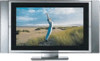
... TV Setting Up the TV Welcome 13 Package Contents 13 Features 13 Overview 15 TV Controls and Connectors 16 Display unit 16 Media receiver unit Front Panel 17 Media receiver unit Rear Panel 18 Installing the TV 20 Basic Connections: Connecting a Cable or Antenna 22 Cable or Antenna Only 23... Cable and Antenna Only 24 Cable Box and Cable Only 25 Cable Box Only 27 Connecting Optional Equipment 29 About Using S VIDEO 29 VCR and ...
... TV Setting Up the TV Welcome 13 Package Contents 13 Features 13 Overview 15 TV Controls and Connectors 16 Display unit 16 Media receiver unit Front Panel 17 Media receiver unit Rear Panel 18 Installing the TV 20 Basic Connections: Connecting a Cable or Antenna 22 Cable or Antenna Only 23... Cable and Antenna Only 24 Cable Box and Cable Only 25 Cable Box Only 27 Connecting Optional Equipment 29 About Using S VIDEO 29 VCR and ...
Operating Instructions
Page 16
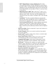
... and more video information to send more natural-looking. • Newly developed PDP driver IC: Achieves high-precision gamma characteristics, using Sony's unique digital technology. s Favorite Channels: Allows you to preview and select from eight of detail (Reality) and smoothness (Clarity) ...8482;-XU): (Twin View™) Allows you to other devices (such as digital set -top box (HD1080i, 720p) connections. s Parental Control: V-Chip technology allows parents to view on Memory Stick media. s Component Video Inputs: Offers the best video quality for DVD (480p, 480i), and digital ...
... and more video information to send more natural-looking. • Newly developed PDP driver IC: Achieves high-precision gamma characteristics, using Sony's unique digital technology. s Favorite Channels: Allows you to preview and select from eight of detail (Reality) and smoothness (Clarity) ...8482;-XU): (Twin View™) Allows you to other devices (such as digital set -top box (HD1080i, 720p) connections. s Parental Control: V-Chip technology allows parents to view on Memory Stick media. s Component Video Inputs: Offers the best video quality for DVD (480p, 480i), and digital ...
Operating Instructions
Page 20
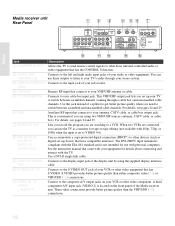
...standard and is convenient if you are using two VHF/UHF sources (antenna, CATV cable, or cable box). S VIDEO provides better picture quality than the VHF/UHF (4) connections. 18 The DVI-HDTV input terminal... that connects to your antenna, CATV cable, or cable box output jack. qa VIDEO IN 1/3 VIDEO/ L-AUDIO-R Connect to the composite A/V output jacks on the front panel of the Media receiver unit. A third component A/V input jack (VIDEO ... S OUT Allows the TV to send remote control signals to other Sony infrared-controlled audio or video equipment that have compatible interfaces.
...standard and is convenient if you are using two VHF/UHF sources (antenna, CATV cable, or cable box). S VIDEO provides better picture quality than the VHF/UHF (4) connections. 18 The DVI-HDTV input terminal... that connects to your antenna, CATV cable, or cable box output jack. qa VIDEO IN 1/3 VIDEO/ L-AUDIO-R Connect to the composite A/V output jacks on the front panel of the Media receiver unit. A third component A/V input jack (VIDEO ... S OUT Allows the TV to send remote control signals to other Sony infrared-controlled audio or video equipment that have compatible interfaces.

Operating Instructions
Page 31
...carries only the video signal, you can use an S VIDEO cable for sound, as shown below. Example of an S VIDEO Connection Rear of Media receiver unit S VIDEO cable Equipment with DVI-HDTV connector Camcorder Audio Receiver Sub Woofer See Page 30 32 34 36 38 40 42 43 44... Tape Editing Satellite Receiver Satellite Receiver and VCR DVD Player with Component Video Connectors DVD Player with S VIDEO and Audio Connectors Digital TV Set-Top Box with Component Video Connectors Digital Satelite Receiver with S VIDEO AUDIO OUT (VAR/FIX) R-AUDIO-L SUBWOOFER OUT (VAR) 1 3 R-AUDIO-L VIDEO S VIDEO ...
...carries only the video signal, you can use an S VIDEO cable for sound, as shown below. Example of an S VIDEO Connection Rear of Media receiver unit S VIDEO cable Equipment with DVI-HDTV connector Camcorder Audio Receiver Sub Woofer See Page 30 32 34 36 38 40 42 43 44... Tape Editing Satellite Receiver Satellite Receiver and VCR DVD Player with Component Video Connectors DVD Player with S VIDEO and Audio Connectors Digital TV Set-Top Box with Component Video Connectors Digital Satelite Receiver with S VIDEO AUDIO OUT (VAR/FIX) R-AUDIO-L SUBWOOFER OUT (VAR) 1 3 R-AUDIO-L VIDEO S VIDEO ...
Operating Instructions
Page 32
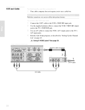
...Using This Connection with Dual Picture (Twin View, etc.) Features With this connection if: s Your cable company does not require you can use a cable box. To connect the VCR and cable 1 Connect the CATV cable to the VCR's VHF/UHF input jack. 2 Use the supplied antenna cable to connect ... jack. 3 Use an A/V cable to connect the VCR's A/V output jacks to use all the dual picture features. See page 29. Using S VIDEO jacks? Rear of Media receiver unit AUDIO OUT (VAR/FIX) R-AUDIO-L SUBWOOFER OUT (VAR) VHF/UHF TO CONVERTER AUX 1 DVI-HDTV R-AUDIO-L 6 3 R-AUDIO-L VIDEO S VIDEO VIDEO IN...
...Using This Connection with Dual Picture (Twin View, etc.) Features With this connection if: s Your cable company does not require you can use a cable box. To connect the VCR and cable 1 Connect the CATV cable to the VCR's VHF/UHF input jack. 2 Use the supplied antenna cable to connect ... jack. 3 Use an A/V cable to connect the VCR's A/V output jacks to use all the dual picture features. See page 29. Using S VIDEO jacks? Rear of Media receiver unit AUDIO OUT (VAR/FIX) R-AUDIO-L SUBWOOFER OUT (VAR) VHF/UHF TO CONVERTER AUX 1 DVI-HDTV R-AUDIO-L 6 3 R-AUDIO-L VIDEO S VIDEO VIDEO IN...
Operating Instructions
Page 35
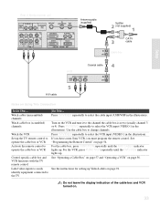
...have a non-Sony VCR, you must program the remote control. For the VCR, press FUNCTION repeatedly until the SAT/CABLE indicator lights up the TV remote control to operate the cable box or VCR Activate the remote control to operate the cable box or VCR Control specific cable box and VCR ... TV remote control Label video inputs to easily identify equipment connected to change channels. See "Operating a Cable Box" on page 57 and "Operating a VCR" on . 33 Do not leave the display indication of Media receiver unit AUDIO OUT (VAR/FIX) R-AUDIO-L SUBWOOFER OUT (VAR) VHF/UHF TO CONVERTER AUX 1...
...have a non-Sony VCR, you must program the remote control. For the VCR, press FUNCTION repeatedly until the SAT/CABLE indicator lights up the TV remote control to operate the cable box or VCR Activate the remote control to operate the cable box or VCR Control specific cable box and VCR ... TV remote control Label video inputs to easily identify equipment connected to change channels. See "Operating a Cable Box" on page 57 and "Operating a VCR" on . 33 Do not leave the display indication of Media receiver unit AUDIO OUT (VAR/FIX) R-AUDIO-L SUBWOOFER OUT (VAR) VHF/UHF TO CONVERTER AUX 1...
Operating Instructions
Page 45
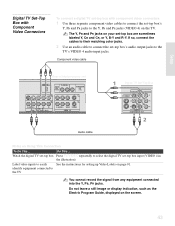
... and CR, or Y, B-Y and R-Y. The Y, PB and PR jacks on your set -top box's Y, PB and PR jacks to the Y, PB and PR jacks (VIDEO 4) on page 91. Component video cable Rear of Media receiver unit AUDIO IN CONTROL S OUT AV MOUSE 4 AUDIO OUT (VAR/FIX) R-AUDIO-L SUBWOOFER OUT... (VAR) 1 5 3 R-AUDIO-L Y PB PR HD/DVD IN ( 1080i / 720p / 480p / 480i ) R-AUDIO-L VIDEO S VIDEO VIDEO IN Digital TV Set-Top Box Audio cable Notes on the screen...
... and CR, or Y, B-Y and R-Y. The Y, PB and PR jacks on your set -top box's Y, PB and PR jacks to the Y, PB and PR jacks (VIDEO 4) on page 91. Component video cable Rear of Media receiver unit AUDIO IN CONTROL S OUT AV MOUSE 4 AUDIO OUT (VAR/FIX) R-AUDIO-L SUBWOOFER OUT... (VAR) 1 5 3 R-AUDIO-L Y PB PR HD/DVD IN ( 1080i / 720p / 480p / 480i ) R-AUDIO-L VIDEO S VIDEO VIDEO IN Digital TV Set-Top Box Audio cable Notes on the screen...
Operating Instructions
Page 51
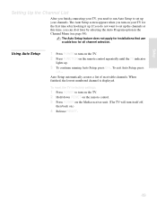
... until the TV indicator lights up. 3 To continue running Auto Setup, press CH+. The Auto Setup feature does not apply for installations that use a cable box for the first time after hooking it later by selecting the Auto Program option in the Channel Menu (see page 84). To reset the TV... Setup screen appears when you can do not want to turn on the TV. 2 Hold down RESET on the remote control. 3 Press POWER on the Media receiver unit. (The TV will turn itself off, then back on.) 4 Release RESET. 49
... until the TV indicator lights up. 3 To continue running Auto Setup, press CH+. The Auto Setup feature does not apply for installations that use a cable box for the first time after hooking it later by selecting the Auto Program option in the Channel Menu (see page 84). To reset the TV... Setup screen appears when you can do not want to turn on the TV. 2 Hold down RESET on the remote control. 3 Press POWER on the Media receiver unit. (The TV will turn itself off, then back on.) 4 Release RESET. 49
Operating Instructions
Page 100
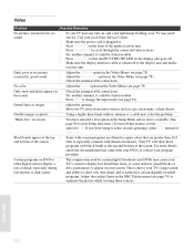
...Double images or ghosts s Using a highly directional outdoor antenna or a cable may need sound service. "Black box" on screen s You have selected a text option in the Setup Menu and no picture (screen lit), ...(this feature, set the Caption Vision option to select closed captioning, select CC1 instead of the media receiver unit. s Press POWER on DVD or s other digital sources display a loss of detail... PIC OFF so that the PICUTRE OFF LED on , and a red light keeps flashing, your local Sony Service Center. No color s Adjust the Color option in the Video Menu (see page 78). it ...
...Double images or ghosts s Using a highly directional outdoor antenna or a cable may need sound service. "Black box" on screen s You have selected a text option in the Setup Menu and no picture (screen lit), ...(this feature, set the Caption Vision option to select closed captioning, select CC1 instead of the media receiver unit. s Press POWER on DVD or s other digital sources display a loss of detail... PIC OFF so that the PICUTRE OFF LED on , and a red light keeps flashing, your local Sony Service Center. No color s Adjust the Color option in the Video Menu (see page 78). it ...
Marketing Specifications
Page 2
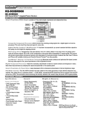
...D): • Weight: KE-50XBR900: KE-50XBR900: 121.2 lbs. 617/8" x 333/4" x 41/4" (157.3 x 85.6 x 10.8mm) KE-42XBR900: 533/8"x 281/2"x 41/8" (135.3 x 72 x 10.3mm) MBT-XBR900 (Media Box): 167/8" x 41/8" x 141/8" (43 x 10.5 x 36mm) PDM-5000 (KE-50XBR900): (55kgs) KE-42XBR900: 99.2 lbs....x 85.6 x 10.8mm) PDM-4200 (KE-42XBR900) 5.32" x 2.83" x 0.4" (135.2 x 72.0 x 10.2mm) ©2002 Sony Electronics Inc. Product Information KE-50XBR900 KE- 42XBR900 XBR Plasma WEGA™ Integrated Plasma Television KEY TECHNOLOGY Sony's Proprietary WEGA Engine consists of 4 key technologies engineered and ...
...D): • Weight: KE-50XBR900: KE-50XBR900: 121.2 lbs. 617/8" x 333/4" x 41/4" (157.3 x 85.6 x 10.8mm) KE-42XBR900: 533/8"x 281/2"x 41/8" (135.3 x 72 x 10.3mm) MBT-XBR900 (Media Box): 167/8" x 41/8" x 141/8" (43 x 10.5 x 36mm) PDM-5000 (KE-50XBR900): (55kgs) KE-42XBR900: 99.2 lbs....x 85.6 x 10.8mm) PDM-4200 (KE-42XBR900) 5.32" x 2.83" x 0.4" (135.2 x 72.0 x 10.2mm) ©2002 Sony Electronics Inc. Product Information KE-50XBR900 KE- 42XBR900 XBR Plasma WEGA™ Integrated Plasma Television KEY TECHNOLOGY Sony's Proprietary WEGA Engine consists of 4 key technologies engineered and ...
Service Manual
Page 6
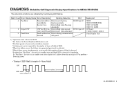
...Low when fan IC6200 pin #2 fan in a standby state after display for 1 minute about 3s KE-50XBR900(UC) 5 Panel malfunction Detects during communication detected with little number of times of LED. *When ...LED blink (example of 4 times blink) ON OFF every about 0.3s about the message of regulation. Receiver box. Repair part • FAN • FAN CONNECTOR • SET 11V LINE • SET 5V LINE ...DP board • Q1612, Q1613, Q1614 Panel Display Unit 1) *Operation count is in Media function normally. In "Fan Error", the unit is based on WDT. *For flashes, the Power/...
...Low when fan IC6200 pin #2 fan in a standby state after display for 1 minute about 3s KE-50XBR900(UC) 5 Panel malfunction Detects during communication detected with little number of times of LED. *When ...LED blink (example of 4 times blink) ON OFF every about 0.3s about the message of regulation. Receiver box. Repair part • FAN • FAN CONNECTOR • SET 11V LINE • SET 5V LINE ...DP board • Q1612, Q1613, Q1614 Panel Display Unit 1) *Operation count is in Media function normally. In "Fan Error", the unit is based on WDT. *For flashes, the Power/...
Service Manual
Page 7
... No picture or Power circuit does not work → Large possibility that Media Receiver Box is out of order. In the following case, POWER LED of order KE-50XBR900(UC) 6 Check SET5V or IIC line on H1 board. • When turn on Media Receiver Box, and Fan does not work → Large possibility that Panel Display...
... No picture or Power circuit does not work → Large possibility that Media Receiver Box is out of order. In the following case, POWER LED of order KE-50XBR900(UC) 6 Check SET5V or IIC line on H1 board. • When turn on Media Receiver Box, and Fan does not work → Large possibility that Panel Display...
Service Manual
Page 116
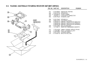
PACKING MATERIALS FOR MEDIA RECEIVER UNIT(MBT-XBR900) REF.NO. PART NO. DESCRIPTION REMARK 208 201 * 4-091-998-01 INDIVIDUAL CARTON 202 * 4-091-737-01 SPACER (B) 203 ! 1-823-863-...) 4-092-940-35 MANUAL, INSTRUCTION (SPANISH) 209 * 4-091-738-01 BOX, ACCESSORY 210 1-477-687-11 REMOTE COMMANDER (RM-927Y) 204 211 1-757-319-41 CABLE, COAXIAL (WITH (F) PLUG) 212 X-4040-886-1 ASSY, CLEANING CLOTH 202 213 213 * 4-091-734-01 CUSHION, RIGHT 214 * 3-704-297-01 BAG, PROTECTION 201 KE-50XBR900(UC) 5-8 5-5.
PACKING MATERIALS FOR MEDIA RECEIVER UNIT(MBT-XBR900) REF.NO. PART NO. DESCRIPTION REMARK 208 201 * 4-091-998-01 INDIVIDUAL CARTON 202 * 4-091-737-01 SPACER (B) 203 ! 1-823-863-...) 4-092-940-35 MANUAL, INSTRUCTION (SPANISH) 209 * 4-091-738-01 BOX, ACCESSORY 210 1-477-687-11 REMOTE COMMANDER (RM-927Y) 204 211 1-757-319-41 CABLE, COAXIAL (WITH (F) PLUG) 212 X-4040-886-1 ASSY, CLEANING CLOTH 202 213 213 * 4-091-734-01 CUSHION, RIGHT 214 * 3-704-297-01 BAG, PROTECTION 201 KE-50XBR900(UC) 5-8 5-5.


