The Sony Guide to Home Theater
Page 35
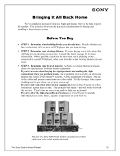
Determine your best bet. Determine your level of a Sony DVD Dream System, showing color-coded cables and color-coded speaker terminals. At Sony, we realize that you already have. Now is the time to start. It's like Sony's DVD Dream™ systems. All the equipment will work well with the receiver. Determine what building blocks you...
Determine your best bet. Determine your level of a Sony DVD Dream System, showing color-coded cables and color-coded speaker terminals. At Sony, we realize that you already have. Now is the time to start. It's like Sony's DVD Dream™ systems. All the equipment will work well with the receiver. Determine what building blocks you...
The Sony Guide to Home Theater
Page 40
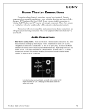
...than one way to Home Theater 40 The Sony Guide to do the job. Left plugs and jacks are used, for Left. This section will review some cases, 5.1-channel connections are coded in Red. Right plugs and jacks are generally color-coded red for Right and white for example in... components to an A/V receiver. Line-level analog audio jacks are coded in white. These are usually color-coded so you don't mix them up most common home theater connections, and help guide you may have imagined. These Sony systems go even further with clear directions and easy-to-follow diagrams...
...than one way to Home Theater 40 The Sony Guide to do the job. Left plugs and jacks are used, for Left. This section will review some cases, 5.1-channel connections are coded in Red. Right plugs and jacks are generally color-coded red for Right and white for example in... components to an A/V receiver. Line-level analog audio jacks are coded in white. These are usually color-coded so you don't mix them up most common home theater connections, and help guide you may have imagined. These Sony systems go even further with clear directions and easy-to-follow diagrams...
The Sony Guide to Home Theater
Page 41
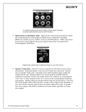
...," "hot" or "plus" terminal on the A/V receiver to the corresponding terminal on the insulation, so you in position. Speaker cables are usually coded to drive each speaker. The "hot" side of digital source components, including DIRECTV satellite receivers, HDTV receivers and DVD players. The... Sony Guide to an A/V receiver. ƒ Optical and Coaxial Digital Audio. 5.1-channel analog audio jacks enable a Super Audio CD player to deliver multi...
...," "hot" or "plus" terminal on the A/V receiver to the corresponding terminal on the insulation, so you in position. Speaker cables are usually coded to drive each speaker. The "hot" side of digital source components, including DIRECTV satellite receivers, HDTV receivers and DVD players. The... Sony Guide to an A/V receiver. ƒ Optical and Coaxial Digital Audio. 5.1-channel analog audio jacks enable a Super Audio CD player to deliver multi...
The Sony Guide to Home Theater
Page 43
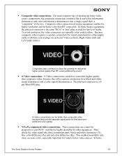
... (Y), blue color difference (PB) and red color difference (PR). In home The Sony Guide to deliver far higher picture quality than composite video because they provide separate signal paths...Video connections can deliver somewhat higher quality than RF connection. These connections are typically color-coded yellow. The physical connector is the same "RCA" or "pin" plug as ...equipment enables far higher resolution and far better color than composite video, because they 're highly desirable for line-level audio. ƒ Composite video connections. This enables beautifully rich,...
... (Y), blue color difference (PB) and red color difference (PR). In home The Sony Guide to deliver far higher picture quality than composite video because they provide separate signal paths...Video connections can deliver somewhat higher quality than RF connection. These connections are typically color-coded yellow. The physical connector is the same "RCA" or "pin" plug as ...equipment enables far higher resolution and far better color than composite video, because they 're highly desirable for line-level audio. ƒ Composite video connections. This enables beautifully rich,...
The Sony Guide to Home Theater
Page 44
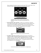
...from piracy. The physical connector is also secured by HDCP technology to a "high scanning," "High Definition monitor" or "High Definition upgradeable" television. The physical cable usually has a D-sub 15-pin connector that...spectacular, uncompressed digital-to-digital transport of video: Red, Green and Blue, abbreviated R/G/B. The Sony Guide to the television. ƒ R/G/B component video connection. Another way of connecting a ...same "RCA" or "pin" plugs as used for line-level audio, typically coded green (Y), blue (PB) and red (PR). The D-sub 15-pin interface supports component video ...
...from piracy. The physical connector is also secured by HDCP technology to a "high scanning," "High Definition monitor" or "High Definition upgradeable" television. The physical cable usually has a D-sub 15-pin connector that...spectacular, uncompressed digital-to-digital transport of video: Red, Green and Blue, abbreviated R/G/B. The Sony Guide to the television. ƒ R/G/B component video connection. Another way of connecting a ...same "RCA" or "pin" plugs as used for line-level audio, typically coded green (Y), blue (PB) and red (PR). The D-sub 15-pin interface supports component video ...

Primary User Manual
Page 24
... red, white to connectors. Example of an S VIDEO Connection TV SETUP S VIDEO cable Equipment with an Optical IN Connector Using the CONTROL S Feature See Page 24 26 28 30 32 34 36 37 38 39 40 ✍ If you are often color-coded to white, etc. Because S VIDEO carries only the video...
... red, white to connectors. Example of an S VIDEO Connection TV SETUP S VIDEO cable Equipment with an Optical IN Connector Using the CONTROL S Feature See Page 24 26 28 30 32 34 36 37 38 39 40 ✍ If you are often color-coded to white, etc. Because S VIDEO carries only the video...
Primary User Manual
Page 25
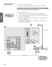
...DV/MICROMV L AUDIO R DIGITAL AUDIO (OPTICAL) OUT PCM/DOLBY DIGITAL SERVICE ONLY VCR Coaxial cable CATV cable SETUP SETUP A/V cable Cables are often color-coded to the TV's A/V input jacks. 4 Run the Auto Setup program, as described in "Setting Up the Channel List" on page 41. See page 23. About .../UHF input jack. 2 Use a coaxial cable to connect the VCR's VHF/UHF output jack to the TV's CABLE jack. 3 Use an A/V cable to connect the VCR's A/V output jacks to connectors. Setup SETUP SETUP TV S VIDEO VIDEO IN 13 4 MONITOR AUDIO OUT OUT (VAR/FIX) HD/DVD IN (1080i/720p/480p...
...DV/MICROMV L AUDIO R DIGITAL AUDIO (OPTICAL) OUT PCM/DOLBY DIGITAL SERVICE ONLY VCR Coaxial cable CATV cable SETUP SETUP A/V cable Cables are often color-coded to the TV's A/V input jacks. 4 Run the Auto Setup program, as described in "Setting Up the Channel List" on page 41. See page 23. About .../UHF input jack. 2 Use a coaxial cable to connect the VCR's VHF/UHF output jack to the TV's CABLE jack. 3 Use an A/V cable to connect the VCR's A/V output jacks to connectors. Setup SETUP SETUP TV S VIDEO VIDEO IN 13 4 MONITOR AUDIO OUT OUT (VAR/FIX) HD/DVD IN (1080i/720p/480p...

Primary User Manual
Page 28
...up Video Labels on page 51. See "Programming the Remote Control" on Using This Connection To Do This ... Connect red to red, white to select the VCR input (VIDEO 1 in the illustration). Press TV/VIDEO repeatedly to white, ...the instructions for setting up the TV remote control to operate the cable box or VCR If you have a non-Sony VCR, you programmed for the VCR. Watch the VCR Press TV/VIDEO repeatedly to select the ... cable 6 Cable box 4 VCR SETUP SETUP SETUP 5 A/V cable Cables are often color-coded to the TV 27 SETUP identify equipment connected to connectors.
...up Video Labels on page 51. See "Programming the Remote Control" on Using This Connection To Do This ... Connect red to red, white to select the VCR input (VIDEO 1 in the illustration). Press TV/VIDEO repeatedly to white, ...the instructions for setting up the TV remote control to operate the cable box or VCR If you have a non-Sony VCR, you programmed for the VCR. Watch the VCR Press TV/VIDEO repeatedly to select the ... cable 6 Cable box 4 VCR SETUP SETUP SETUP 5 A/V cable Cables are often color-coded to the TV 27 SETUP identify equipment connected to connectors.

Primary User Manual
Page 29
... AUDIO R CONTROL S OUT IN L AUDIO R Playback VCR A/V cable DIGITAL AUDIO (OPTICAL) OUT PCM/DOLBY DIGITAL SERVICE ONLY Recording VCR A/V cable Cables are often color-coded to the TV's MONITOR OUT jacks. By connecting them as shown below, you record from one VCR to white, etc. To connect two VCRs for Tape Editing...) what is being recorded. SETUP Setup SETUP Two VCRs for tape editing 1 Use an A/V cable to connect the playback VCR's A/V output jacks to the TV's A/V input jacks. 2 Use an A/V cable to connect the recording VCR's A/V input jacks to connectors. See page 23.
... AUDIO R CONTROL S OUT IN L AUDIO R Playback VCR A/V cable DIGITAL AUDIO (OPTICAL) OUT PCM/DOLBY DIGITAL SERVICE ONLY Recording VCR A/V cable Cables are often color-coded to the TV's MONITOR OUT jacks. By connecting them as shown below, you record from one VCR to white, etc. To connect two VCRs for Tape Editing...) what is being recorded. SETUP Setup SETUP Two VCRs for tape editing 1 Use an A/V cable to connect the playback VCR's A/V output jacks to the TV's A/V input jacks. 2 Use an A/V cable to connect the recording VCR's A/V input jacks to connectors. See page 23.

Primary User Manual
Page 31
... IN L AUDIO R DIGITAL AUDIO (OPTICAL) OUT PCM/DOLBY DIGITAL SERVICE ONLY Satellite receiver Satellite antenna cable A/V cable Cables are often color-coded to the TV's CABLE or VHF/UHF jack. 4 Run the Auto Setup program, as described in "Setting Up the Channel List" on page 41....satellite antenna cable to the satellite receiver's satellite input jack. 2 Use an A/V cable to connect the satellite receiver's A/V output jacks to the TV's A/V input jacks. 3 Connect a cable from your cable or antenna to connectors. SETUP Setup SETUP Satellite Receiver Using S VIDEO jacks? Connect red...
... IN L AUDIO R DIGITAL AUDIO (OPTICAL) OUT PCM/DOLBY DIGITAL SERVICE ONLY Satellite receiver Satellite antenna cable A/V cable Cables are often color-coded to the TV's CABLE or VHF/UHF jack. 4 Run the Auto Setup program, as described in "Setting Up the Channel List" on page 41....satellite antenna cable to the satellite receiver's satellite input jack. 2 Use an A/V cable to connect the satellite receiver's A/V output jacks to the TV's A/V input jacks. 3 Connect a cable from your cable or antenna to connectors. SETUP Setup SETUP Satellite Receiver Using S VIDEO jacks? Connect red...

Primary User Manual
Page 34
A/V cable VCR CATV cable A/V cable SETUP SETUP SETUP SETUP 33 SETUP Setup TV DVI - Connect red to red, white to connectors. HDTV IN 7 VIDEO TS/DV/MICROMV Coaxial cable S VIDEO VIDEO IN 1 3 4 MONITOR AUDIO OUT OUT (VAR/FIX) HD/DVD IN (1080i/720p/480p/480i) 5 6 Y PB VIDEO L (MONO) AUDIO R PR L AUDIO R CONTROL S OUT IN L AUDIO R DIGITAL AUDIO (OPTICAL) OUT PCM/DOLBY DIGITAL SERVICE ONLY Satellite receiver Satellite antenna cable Cables are often color-coded to white, etc.
A/V cable VCR CATV cable A/V cable SETUP SETUP SETUP SETUP 33 SETUP Setup TV DVI - Connect red to red, white to connectors. HDTV IN 7 VIDEO TS/DV/MICROMV Coaxial cable S VIDEO VIDEO IN 1 3 4 MONITOR AUDIO OUT OUT (VAR/FIX) HD/DVD IN (1080i/720p/480p/480i) 5 6 Y PB VIDEO L (MONO) AUDIO R PR L AUDIO R CONTROL S OUT IN L AUDIO R DIGITAL AUDIO (OPTICAL) OUT PCM/DOLBY DIGITAL SERVICE ONLY Satellite receiver Satellite antenna cable Cables are often color-coded to white, etc.

Primary User Manual
Page 35
... video connectors 1 Use a component video cable, or three composite video cables, to connect the DVD player's Y, PB and PR jacks to the TV's VIDEO 5 audio input jacks. HDTV IN 7 VIDEO TV TS/DV/MICROMV S VIDEO VIDEO IN 1 3 4 MONITOR AUDIO OUT OUT (VAR/FIX) HD/DVD IN (1080i/720p/480p/480i) 5 6... or Y, B-Y and R-Y. To connect a DVD player with Component Video Connectors For best results, use this connection if your DVD player are often color-coded to white, etc. If so, connect the cables to like colors. 2 Use an audio cable to connect the DVD player's audio output jacks to the...
... video connectors 1 Use a component video cable, or three composite video cables, to connect the DVD player's Y, PB and PR jacks to the TV's VIDEO 5 audio input jacks. HDTV IN 7 VIDEO TV TS/DV/MICROMV S VIDEO VIDEO IN 1 3 4 MONITOR AUDIO OUT OUT (VAR/FIX) HD/DVD IN (1080i/720p/480p/480i) 5 6... or Y, B-Y and R-Y. To connect a DVD player with Component Video Connectors For best results, use this connection if your DVD player are often color-coded to white, etc. If so, connect the cables to like colors. 2 Use an audio cable to connect the DVD player's audio output jacks to the...

Primary User Manual
Page 37
Cables are often TV color-coded to select the DVD input (VIDEO 1 in the illustration). Watch the DVD player Press TV/VIDEO repeatedly to connectors. the TV remote control Label video inputs to easily See the instructions for the DVD player. To connect a DVD player with S VIDEO and Audio ...Connectors Use this connection if your DVD player does not have a non-Sony DVD player, you programmed for setting up the TV remote control If you have component video (Y, PB, PR) jacks. Do This ... Set up Video Labels on page 52. Control...
Cables are often TV color-coded to select the DVD input (VIDEO 1 in the illustration). Watch the DVD player Press TV/VIDEO repeatedly to connectors. the TV remote control Label video inputs to easily See the instructions for the DVD player. To connect a DVD player with S VIDEO and Audio ...Connectors Use this connection if your DVD player does not have a non-Sony DVD player, you programmed for setting up the TV remote control If you have component video (Y, PB, PR) jacks. Do This ... Set up Video Labels on page 52. Control...

Primary User Manual
Page 38
... 103-104. If you prefer, however, you have a mono camcorder, connect its audio output jack to the TV 37 TV Front Video Panel S400 DV/MICROMV A/V cable Cables are often color-coded to the TV's A/V input jacks. SETUP Setup Camcorder Using S VIDEO jacks? For easy connection of a camcorder, the... TV has front A/V input jacks. Do This ... See page 23. To connect a camcorder 1 Open the front video panel,...
... 103-104. If you prefer, however, you have a mono camcorder, connect its audio output jack to the TV 37 TV Front Video Panel S400 DV/MICROMV A/V cable Cables are often color-coded to the TV's A/V input jacks. SETUP Setup Camcorder Using S VIDEO jacks? For easy connection of a camcorder, the... TV has front A/V input jacks. Do This ... See page 23. To connect a camcorder 1 Open the front video panel,...

Primary User Manual
Page 39
... on the audio receiver, and then set the Speaker option to connectors. To connect an audio system 1 Use an audio cable to connect the TV's audio output jacks to control the volume. HDTV IN 7 VIDEO TS/DV/MICROMV L AUDIO R DIGITAL AUDIO (OPTICAL) OUT PCM/DOLBY DIGITAL ...SERVICE ONLY Cables are often color-coded to Off. Connect red to red, white to white. 2 Using the TV's Audio Menu, set the receiver's line input to play the TV's audio through your stereo system. SETUP SETUP SETUP 38 TV S VIDEO VIDEO IN 1 3 4 MONITOR AUDIO OUT OUT...
... on the audio receiver, and then set the Speaker option to connectors. To connect an audio system 1 Use an audio cable to connect the TV's audio output jacks to control the volume. HDTV IN 7 VIDEO TS/DV/MICROMV L AUDIO R DIGITAL AUDIO (OPTICAL) OUT PCM/DOLBY DIGITAL ...SERVICE ONLY Cables are often color-coded to Off. Connect red to red, white to white. 2 Using the TV's Audio Menu, set the receiver's line input to play the TV's audio through your stereo system. SETUP SETUP SETUP 38 TV S VIDEO VIDEO IN 1 3 4 MONITOR AUDIO OUT OUT...
Primary User Manual
Page 47
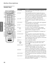
... 49. Press to restore the sound. SETUP SETUP Remote Control Button Descriptions Outside Panel 1 2 3 4 5 MUTING SLEEP SAT/CABLE POWER FUNCTION i.LINK SAT/CABLE TV TV/VIDEO ANT PIC MODE Button 1 MUTING qh 2 SLEEP qj qk ql 3 i.LINK ENTER 6 7 8 WIDE MODE FLIP OPEN INDEX TWIN VIEW w; 9 MENU ...from the Menu. wa qa MEMORY STICK ws MODE PALETTE qs wd DRC qd RESET DISPLAY FAVORITES GUIDE wf qf CODE SET wg JUMP qg FREEZE EXIT wh wj wk TV RM-Y192 4 TV/VIDEO 5 ANT 6 7 INDEX 8 WIDE MODE 9 MENU q; Press repeatedly until Sleep Off appears. While the...
... 49. Press to restore the sound. SETUP SETUP Remote Control Button Descriptions Outside Panel 1 2 3 4 5 MUTING SLEEP SAT/CABLE POWER FUNCTION i.LINK SAT/CABLE TV TV/VIDEO ANT PIC MODE Button 1 MUTING qh 2 SLEEP qj qk ql 3 i.LINK ENTER 6 7 8 WIDE MODE FLIP OPEN INDEX TWIN VIEW w; 9 MENU ...from the Menu. wa qa MEMORY STICK ws MODE PALETTE qs wd DRC qd RESET DISPLAY FAVORITES GUIDE wf qf CODE SET wg JUMP qg FREEZE EXIT wh wj wk TV RM-Y192 4 TV/VIDEO 5 ANT 6 7 INDEX 8 WIDE MODE 9 MENU q; Press repeatedly until Sleep Off appears. While the...

Primary User Manual
Page 49
... ENTER WIDE MODE INDEX TWIN VIEW VOL MENU CH MODE MEMORY STICK PALETTE RESET DRC FAVORITES GUIDE DISPLAY CODE SET FREEZE EXIT JUMP TV RM-Y192 MUTING SLEEP SAT/CABLE POWER wg SYSTEM OFF wh TV/VCR VCR/DVD e; SETUP SETUP SETUP 48 For details, see "Using the Audio Menu" on page 94... cover automatically switches the remote control to operate your VCR or DVD player, depending on the position of the VCR. i.LINK-connected devices are not Sony brand. You can program one video source for each switch position. Also available in the Audio Menu.
... ENTER WIDE MODE INDEX TWIN VIEW VOL MENU CH MODE MEMORY STICK PALETTE RESET DRC FAVORITES GUIDE DISPLAY CODE SET FREEZE EXIT JUMP TV RM-Y192 MUTING SLEEP SAT/CABLE POWER wg SYSTEM OFF wh TV/VCR VCR/DVD e; SETUP SETUP SETUP 48 For details, see "Using the Audio Menu" on page 94... cover automatically switches the remote control to operate your VCR or DVD player, depending on the position of the VCR. i.LINK-connected devices are not Sony brand. You can program one video source for each switch position. Also available in the Audio Menu.
Primary User Manual
Page 50
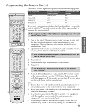
...remove the batteries to replace them one by one code number is listed, use the following procedure to AV1. 3 Press CODE SET. 4 Enter the three-digit manufacturer's code number. 5 Press ENTER. SETUP MUTING SLEEP SAT/CABLE POWER SYSTEM OFF TV/VCR VCR/DVD i.LINK Sony Equipment i.LINK 8 mm VCR VHS VCR DVD... player Switch Position on page 50, and find the three-digit code number for the manufacturer of step 4, or you must be reset. 49 SETUP SETUP MTS...
...remove the batteries to replace them one by one code number is listed, use the following procedure to AV1. 3 Press CODE SET. 4 Enter the three-digit manufacturer's code number. 5 Press ENTER. SETUP MUTING SLEEP SAT/CABLE POWER SYSTEM OFF TV/VCR VCR/DVD i.LINK Sony Equipment i.LINK 8 mm VCR VHS VCR DVD... player Switch Position on page 50, and find the three-digit code number for the manufacturer of step 4, or you must be reset. 49 SETUP SETUP MTS...

Primary User Manual
Page 51
... 331, 332 314, 330, 336, 337 331 Laserdisc Players Manufacturer Sony Panasonic Pioneer Code 701 704, 710 702 i.LINK Controls Function Rewind, Play, Fast-forward, Record, Stop, Pause Code 901 DVD Players Manufacturer Sony Apex General Electric Hitachi JVC Magnavox Mitsubishi Oritron Panasonic Philips Pioneer RCA/Proscan... 220, 221 214, 215 209, 210, 211 216, 217 212, 213 Satellite Receivers Manufacturer Sony Dish Network Echostar General Electric Hitachi Hughes Mitsubishi Panasonic RCA/ PROSCAN Toshiba Code 801 810 810 802 805 804 809 803 802, 808 806, 807 SETUP SETUP SETUP Remote ...
... 331, 332 314, 330, 336, 337 331 Laserdisc Players Manufacturer Sony Panasonic Pioneer Code 701 704, 710 702 i.LINK Controls Function Rewind, Play, Fast-forward, Record, Stop, Pause Code 901 DVD Players Manufacturer Sony Apex General Electric Hitachi JVC Magnavox Mitsubishi Oritron Panasonic Philips Pioneer RCA/Proscan... 220, 221 214, 215 209, 210, 211 216, 217 212, 213 Satellite Receivers Manufacturer Sony Dish Network Echostar General Electric Hitachi Hughes Mitsubishi Panasonic RCA/ PROSCAN Toshiba Code 801 810 810 802 805 804 809 803 802, 808 806, 807 SETUP SETUP SETUP Remote ...

Primary User Manual
Page 85
...'s i.LINK jack to either of the i.LINK device to be connected. i.LINK SETUP i.LINK SETUP TV DVI - To connect an i.LINK device that supports an EIA-775A connection 1 Using an i.LINK ...either of the TV's i.LINK jacks. 2 Using an A/V cable, connect the i.LINK device's A/V output jacks to the TV's VIDEO 3 A/V input jacks. ✍ Only one i.LINK cable should connect the TV and any given ...Devices ✍ Before connecting this unit to i.LINK-compatible equipment, read the instruction manual of the TV's i.LINK jacks. Connect red to red, white to connectors. HDTV IN 7 VIDEO TS/DV/MICROMV...
...'s i.LINK jack to either of the i.LINK device to be connected. i.LINK SETUP i.LINK SETUP TV DVI - To connect an i.LINK device that supports an EIA-775A connection 1 Using an i.LINK ...either of the TV's i.LINK jacks. 2 Using an A/V cable, connect the i.LINK device's A/V output jacks to the TV's VIDEO 3 A/V input jacks. ✍ Only one i.LINK cable should connect the TV and any given ...Devices ✍ Before connecting this unit to i.LINK-compatible equipment, read the instruction manual of the TV's i.LINK jacks. Connect red to red, white to connectors. HDTV IN 7 VIDEO TS/DV/MICROMV...


