Service Manual
Page 3
...KDL-40V3000 Only) ......... 34 DF2 Board Schematic Diagram (KDL-46V3000/46VL130 Only 37 DF3 Board Schematic Diagram (KDL-46V3000/46VL130 Only 40 FB3 Board Schematic Diagram (1 of 15 43 FB3 Board Schematic Diagram (2 of 15 44 FB3 Board Schematic Diagram (3 of 15... Diagram (KDL-40V3000 Only 25 3-3-2. ETC-Inverter MT Board Removal 18 SECTION 2: SERVICE ADJUSTMENTS 19 2-1. Accessing Service Adjustments 19 2-3. Updating Model Information after Replacing the FB1 Board 21 SECTION 3: DIAGRAMS 22 3-1. Stay (Bracket) Removal 17 1-10.LCD Panel Removal 17 1-11. Rear Cover Assembly...
...KDL-40V3000 Only) ......... 34 DF2 Board Schematic Diagram (KDL-46V3000/46VL130 Only 37 DF3 Board Schematic Diagram (KDL-46V3000/46VL130 Only 40 FB3 Board Schematic Diagram (1 of 15 43 FB3 Board Schematic Diagram (2 of 15 44 FB3 Board Schematic Diagram (3 of 15... Diagram (KDL-40V3000 Only 25 3-3-2. ETC-Inverter MT Board Removal 18 SECTION 2: SERVICE ADJUSTMENTS 19 2-1. Accessing Service Adjustments 19 2-3. Updating Model Information after Replacing the FB1 Board 21 SECTION 3: DIAGRAMS 22 3-1. Stay (Bracket) Removal 17 1-10.LCD Panel Removal 17 1-11. Rear Cover Assembly...
Service Manual
Page 7
...diagrams and the electrical parts list. disconnect the AC adapter when replacing the backlight (CCFL) or inverter circuit. (High voltage occurs at the inverter circuit at 650Vrms.) always clean the LCD panel with water. LEAKAGE CURRENT HOT CHECK CIRCUIT KDL-40V3000/46V3000/46VL130 7 USE CAUTION WHEN ... when handling the wires or connectors of time. KDL-40V3000/46V3000/46VL130 SAFETY-RELATED COMPONENT WARNING There are critical components used in LCD color TVs that these critical parts be secured using a wrist band. These components are identified with the part number specifi...
...diagrams and the electrical parts list. disconnect the AC adapter when replacing the backlight (CCFL) or inverter circuit. (High voltage occurs at the inverter circuit at 650Vrms.) always clean the LCD panel with water. LEAKAGE CURRENT HOT CHECK CIRCUIT KDL-40V3000/46V3000/46VL130 7 USE CAUTION WHEN ... when handling the wires or connectors of time. KDL-40V3000/46V3000/46VL130 SAFETY-RELATED COMPONENT WARNING There are critical components used in LCD color TVs that these critical parts be secured using a wrist band. These components are identified with the part number specifi...
Service Manual
Page 16
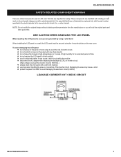
... the connector is securely attached to the Inv 1 After inserting the connector into the Inverter board, push the middle section of the inverter connector to lock on the terminal. 2 Push the right section of the inverter connector and confirm it is securely connected. 3 Push the left section of the... inverter connector and confirm it is securely connected. KDL-40V3000/46V3000/46VL130 16 DF1, DF2, DF3 BOARD AND GF1 BOARD REMOVAL 1 Remove 5 screws, ...
... the connector is securely attached to the Inv 1 After inserting the connector into the Inverter board, push the middle section of the inverter connector to lock on the terminal. 2 Push the right section of the inverter connector and confirm it is securely connected. 3 Push the left section of the... inverter connector and confirm it is securely connected. KDL-40V3000/46V3000/46VL130 16 DF1, DF2, DF3 BOARD AND GF1 BOARD REMOVAL 1 Remove 5 screws, ...
Service Manual
Page 18
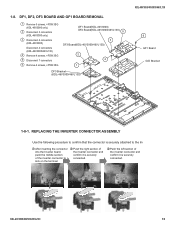
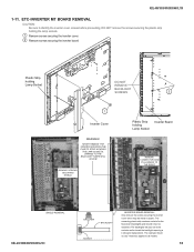
... REMOVE BACKLIGHT SCREWS 2 1 Inverter Cover WARNING! The remaining plastic strip contains sockets for the fluorescent backlights and should never be metal or plastic. The backlights will pop out of the sockets and/or break the backlight requiring a LCD panel replacement. KDL-40V3000/46V3000.../46VL130 1-11. NEVER REMOVE THE SCREWS SECURING THE PLASTIC STRIP HOLDING THE LAMP SOCKETS. The example shown is a 32" model but applies to identify the inverter cover screws before proceeding. DO NOT...
... REMOVE BACKLIGHT SCREWS 2 1 Inverter Cover WARNING! The remaining plastic strip contains sockets for the fluorescent backlights and should never be metal or plastic. The backlights will pop out of the sockets and/or break the backlight requiring a LCD panel replacement. KDL-40V3000/46V3000.../46VL130 1-11. NEVER REMOVE THE SCREWS SECURING THE PLASTIC STRIP HOLDING THE LAMP SOCKETS. The example shown is a 32" model but applies to identify the inverter cover screws before proceeding. DO NOT...
Service Manual
Page 34
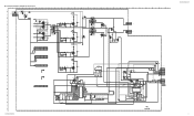
... 8 NC 7 BALANCER_ERR 6 REG12V 5 GND 4 INV_ERR 3 BACK_LIGHT 2 DIMMER 1 GND 1 GND_3 1 GND_3 C6757 0.1 25V B R6805 4.7 C6756 0.1 25V B 5 12V 4 FB 3 GND 2 NC 1 LD CN6701 5P TO BALANCER DF1 INVERTER A-1256-156-A DF1 KDL-40V3000/46V3000/46VL130 34 O - E - M - C - J - N - ☛DF1 BOARD SCHEMATIC DIAGRAM (KDL-40V3000 ONLY) 1 | 2 | 3 | 4 | 5 | 6 | 7 | 8 | 9 | 10 | 11 | 12 | 13 | 14 | 15 | 16 | 17 | 18...
... 8 NC 7 BALANCER_ERR 6 REG12V 5 GND 4 INV_ERR 3 BACK_LIGHT 2 DIMMER 1 GND 1 GND_3 1 GND_3 C6757 0.1 25V B R6805 4.7 C6756 0.1 25V B 5 12V 4 FB 3 GND 2 NC 1 LD CN6701 5P TO BALANCER DF1 INVERTER A-1256-156-A DF1 KDL-40V3000/46V3000/46VL130 34 O - E - M - C - J - N - ☛DF1 BOARD SCHEMATIC DIAGRAM (KDL-40V3000 ONLY) 1 | 2 | 3 | 4 | 5 | 6 | 7 | 8 | 9 | 10 | 11 | 12 | 13 | 14 | 15 | 16 | 17 | 18...
Service Manual
Page 37
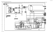
... CN6706 9 NC 8 NC 7 BALANCER_ERR 6 REG12V 5 GND 4 INV_ERR 3 BACK_LIGHT 2 DIMMER 1 GND 1 GND_3 7 12V 6 FB 5 GND 4 NC 3 LD 2 LD 1 LD CN6701 7P TO BALANCER BAT54HT1 D6625 DF2 INVERTER A-1253-585-A DF2 KDL-40V3000/46V3000/46VL130 37
... CN6706 9 NC 8 NC 7 BALANCER_ERR 6 REG12V 5 GND 4 INV_ERR 3 BACK_LIGHT 2 DIMMER 1 GND 1 GND_3 7 12V 6 FB 5 GND 4 NC 3 LD 2 LD 1 LD CN6701 7P TO BALANCER BAT54HT1 D6625 DF2 INVERTER A-1253-585-A DF2 KDL-40V3000/46V3000/46VL130 37
Service Manual
Page 40
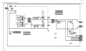
... 4P TO PANEL C6912 15p 6.3kV SL C6914 4700p 50V B C6917 1000p 50V B 1 GND_3 R6901 0 1608 CHIP INV_DRV_1H INV_DRV_1L INV_DRV_2H INV_DRV_2L VCC_12V DF3 INVERTER TO DF2 CN6704 14P CN6900 14 CONN_DET 13 12V 12 NC 11 V-FB1 10 GND 9 INV-DRV-1H 8 GND 7 INV-DRV-1L 6 GND ...5 INV-DRV-2H 4 GND 3 INV-DRV-2L 2 GND 1 1 GND_3 OCP2 A-1253-586-A DF3 P KDL-40V3000/46V3000/46VL130 40 TO GF1 BOARD CN6501 CN6800 3P WHT 391.0 PFC_OUT 1 PRI_GND 3 L6800 100uH C6802 1 450V PT C - E - I - F - C6801 0.1 50V B 2012 R6827 1M 1/10W RN...
... 4P TO PANEL C6912 15p 6.3kV SL C6914 4700p 50V B C6917 1000p 50V B 1 GND_3 R6901 0 1608 CHIP INV_DRV_1H INV_DRV_1L INV_DRV_2H INV_DRV_2L VCC_12V DF3 INVERTER TO DF2 CN6704 14P CN6900 14 CONN_DET 13 12V 12 NC 11 V-FB1 10 GND 9 INV-DRV-1H 8 GND 7 INV-DRV-1L 6 GND ...5 INV-DRV-2H 4 GND 3 INV-DRV-2L 2 GND 1 1 GND_3 OCP2 A-1253-586-A DF3 P KDL-40V3000/46V3000/46VL130 40 TO GF1 BOARD CN6501 CN6800 3P WHT 391.0 PFC_OUT 1 PRI_GND 3 L6800 100uH C6802 1 450V PT C - E - I - F - C6801 0.1 50V B 2012 R6827 1M 1/10W RN...

Service Manual
Page 42
DF3 [INVERTER] CONDUCTOR SIDE 1 2 3 4 5 6 A B ET6900 D6905 A6900 1-873-817-12 (172876212) C6908 D6903 C6917 R6901 C6916 C6914 C6912 JL6917 C6907 D6902 D6907 CN6903 1 2 HV3 HV4 4 1 CN6904 JL6920 ...
DF3 [INVERTER] CONDUCTOR SIDE 1 2 3 4 5 6 A B ET6900 D6905 A6900 1-873-817-12 (172876212) C6908 D6903 C6917 R6901 C6916 C6914 C6912 JL6917 C6907 D6902 D6907 CN6903 1 2 HV3 HV4 4 1 CN6904 JL6920 ...
Service Manual
Page 76
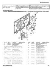
...Specific instructions must be adhered to the instructions for this manual. 4-3. CONNECTORS (Check the Sony Electronics Service Information website for any additional service related issues for "Replacing the Inverter Connector Assembly" in the Disassembly section of this model.) 101 102 103 104 105 106 102 ... for this model, refer to the instructions for "Replacing the Inverter Connector Assembly" in the back of this manual.) 104 1-910-039-02 EARTH CONNECTOR ASSEMBLY (HV2) 105 1-910-037-40 MO1929 CONNECTOR ASSEMBLY (BF) 20P 106 1-821-375-11 BOARD TO BOARD CONNECTOR 80P...
...Specific instructions must be adhered to the instructions for this manual. 4-3. CONNECTORS (Check the Sony Electronics Service Information website for any additional service related issues for "Replacing the Inverter Connector Assembly" in the Disassembly section of this model.) 101 102 103 104 105 106 102 ... for this model, refer to the instructions for "Replacing the Inverter Connector Assembly" in the back of this manual.) 104 1-910-039-02 EARTH CONNECTOR ASSEMBLY (HV2) 105 1-910-037-40 MO1929 CONNECTOR ASSEMBLY (BF) 20P 106 1-821-375-11 BOARD TO BOARD CONNECTOR 80P...
Service Manual
Page 78
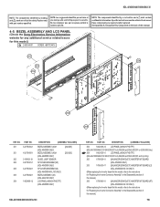
...789-840-11 (BALANCER BOARD) ETC-INVERTER MT BOARD (RT) (KDL-46V3000/46VL130 ONLY) (When replacing the Inverter board for "Replacing the Inverter Connector Assembly" in the back of...marque ! Replace only with part number specified. BEZEL ASSEMBLY AND LCD PANEL (Check the Sony Electronics Service Information website for any additional service related issues for safety. NO....-488-12 DESCRIPTION [ASSEMBLY INCLUDES] BEZEL ASSEMBLY (40)H (KDL-40V3000 ONLY) BEZEL ASSEMBLY (46)H (KDL-46V3000 ONLY) GUIDE, LIGHT SENSOR SP COVER ASSEMBLY(40) (KDL-40V3000 ONLY) SP COVER ASSEMBLY(46)...
...789-840-11 (BALANCER BOARD) ETC-INVERTER MT BOARD (RT) (KDL-46V3000/46VL130 ONLY) (When replacing the Inverter board for "Replacing the Inverter Connector Assembly" in the back of...marque ! Replace only with part number specified. BEZEL ASSEMBLY AND LCD PANEL (Check the Sony Electronics Service Information website for any additional service related issues for safety. NO....-488-12 DESCRIPTION [ASSEMBLY INCLUDES] BEZEL ASSEMBLY (40)H (KDL-40V3000 ONLY) BEZEL ASSEMBLY (46)H (KDL-46V3000 ONLY) GUIDE, LIGHT SENSOR SP COVER ASSEMBLY(40) (KDL-40V3000 ONLY) SP COVER ASSEMBLY(46)...


