Operating Instructions
Page 2
...or splashing and no objects filled with part 15 of important operating and maintenance (servicing) instructions in this TV. "PLAYSTATION" is a registered trademark and "PS3" is encouraged to try to Part 15 of the following WALL-MOUNT BRACKET or TV-stand. Record these numbers in injury.... (1) This device may be fully inserted to the following Sony TVs only with the limits for safety purposes, to which should allow you will not occur in United States and/or other countries. Sony TV Model No. Sony TV-Stand Model No. To Customers Sufficient expertise is desirable to...
...or splashing and no objects filled with part 15 of important operating and maintenance (servicing) instructions in this TV. "PLAYSTATION" is a registered trademark and "PS3" is encouraged to try to Part 15 of the following WALL-MOUNT BRACKET or TV-stand. Record these numbers in injury.... (1) This device may be fully inserted to the following Sony TVs only with the limits for safety purposes, to which should allow you will not occur in United States and/or other countries. Sony TV Model No. Sony TV-Stand Model No. To Customers Sufficient expertise is desirable to...
Operating Instructions
Page 5
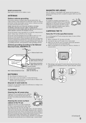
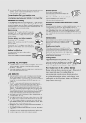
...information with a solution of explosion if battery is covered with dust and it regularly. s Carrying the large size TV requires two or more people. Place your local laws or regulations. To ensure proper ventilation, we recommend removing ... below. The ventilation holes can come in contact with a soft cloth. Do not put stress on the LCD panel. If the plug is incorrectly replaced. Keep any items susceptible to make occasional snapping or popping sounds,...Ground clamps Power service grounding electrode system (NEC Art 250 Part H) BATTERIES s Do not dispose of children's reach.
...information with a solution of explosion if battery is covered with dust and it regularly. s Carrying the large size TV requires two or more people. Place your local laws or regulations. To ensure proper ventilation, we recommend removing ... below. The ventilation holes can come in contact with a soft cloth. Do not put stress on the LCD panel. If the plug is incorrectly replaced. Keep any items susceptible to make occasional snapping or popping sounds,...Ground clamps Power service grounding electrode system (NEC Art 250 Part H) BATTERIES s Do not dispose of children's reach.
Operating Instructions
Page 6
...openings by qualified personnel. It may result in electric shock or damage to the TV. It may touch dangerous voltage points or short out parts that could result in a fire or an electric shock. Leave some space around the TV set as they may result in a fire or an electric shock. It ...may cause a fire or damage to use power-line operated TV sets near water - s Never place ...
...openings by qualified personnel. It may result in electric shock or damage to the TV. It may touch dangerous voltage points or short out parts that could result in a fire or an electric shock. Leave some space around the TV set as they may result in a fire or an electric shock. It ...may cause a fire or damage to use power-line operated TV sets near water - s Never place ...
Operating Instructions
Page 7
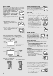
... cause serious injury. This does not indicate a failure. To prevent the TV from toppling over , secure the TV to rain, it may expose you have the same characteristics as the original parts. Do not install this product contains mercury. LCD SCREEN s Although the LCD screen is made with high-precision technology and has effective pixels...
... cause serious injury. This does not indicate a failure. To prevent the TV from toppling over , secure the TV to rain, it may expose you have the same characteristics as the original parts. Do not install this product contains mercury. LCD SCREEN s Although the LCD screen is made with high-precision technology and has effective pixels...
Service Manual
Page 3
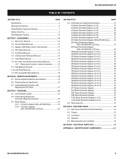
...-40V3000 Only) ......... 34 DF2 Board Schematic Diagram (KDL-46V3000/46VL130 Only 37 DF3 Board Schematic Diagram (KDL-46V3000/46VL130 Only 40 FB3 Board Schematic Diagram (1 of 15 43 FB3 Board Schematic Diagram (2 of 15 44 FB3 Board Schematic Diagram (3 of 15... 67 TUU2 Board Schematic Diagram (1 of 2 69 TUU2 Board Schematic Diagram (2 of 2 70 3-5. Chassis 75 4-3. Bezel Assembly and LCD Panel 78 SECTION 5: ELECTRICAL PARTS LIST 79 APPENDIX A: ENCRYPTION KEY COMPONENTS A-1 KDL-40V3000/46V3000/46VL130 3 Semiconductors 73 SECTION 4: EXPLODED VIEWS 74 4-1. HW1 Board Removal...
...-40V3000 Only) ......... 34 DF2 Board Schematic Diagram (KDL-46V3000/46VL130 Only 37 DF3 Board Schematic Diagram (KDL-46V3000/46VL130 Only 40 FB3 Board Schematic Diagram (1 of 15 43 FB3 Board Schematic Diagram (2 of 15 44 FB3 Board Schematic Diagram (3 of 15... 67 TUU2 Board Schematic Diagram (1 of 2 69 TUU2 Board Schematic Diagram (2 of 2 70 3-5. Chassis 75 4-3. Bezel Assembly and LCD Panel 78 SECTION 5: ELECTRICAL PARTS LIST 79 APPENDIX A: ENCRYPTION KEY COMPONENTS A-1 KDL-40V3000/46V3000/46VL130 3 Semiconductors 73 SECTION 4: EXPLODED VIEWS 74 4-1. HW1 Board Removal...
Service Manual
Page 5
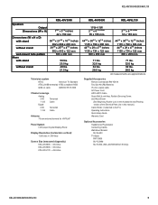
... Wood Screw (See Bag Assy, Rudder Lock in the Accessories and Packing section of the Electrical Parts List in this manual.) Cable Holder (1 attached to the TV) Operating Instructions Quick Setup Guide Warranty Card Optional Accessories Headphones Plug Adaptor Connecting Cables Wall-Mount Bracket... 1-135 Cable Antenna 75-ohm external terminal for VHF/UHF Panel System LCD (Liquid Crystal Display) Panel Display Resolution (horizontal x vertical): 1,920 dots x 1,080 lines Screen Size (measured diagonally) KDL-40V3000 - ~40 inches KDL-46V3000 - ~46 inches KDL-46VL130 - ~46 inches KDL...
... Wood Screw (See Bag Assy, Rudder Lock in the Accessories and Packing section of the Electrical Parts List in this manual.) Cable Holder (1 attached to the TV) Operating Instructions Quick Setup Guide Warranty Card Optional Accessories Headphones Plug Adaptor Connecting Cables Wall-Mount Bracket... 1-135 Cable Antenna 75-ohm external terminal for VHF/UHF Panel System LCD (Liquid Crystal Display) Panel Display Resolution (horizontal x vertical): 1,920 dots x 1,080 lines Screen Size (measured diagonally) KDL-40V3000 - ~40 inches KDL-46V3000 - ~46 inches KDL-46VL130 - ~46 inches KDL...
Service Manual
Page 7
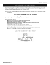
...46VL130 SAFETY-RELATED COMPONENT WARNING There are critical components used in LCD color TVs that these critical parts be replaced only with the part number specified in areas of high humidity for safety. To avoid damaging the LCD panel: do not scratch or press on the schematic diagrams... and the electrical parts list. disconnect the AC adapter when replacing the backlight (...
...46VL130 SAFETY-RELATED COMPONENT WARNING There are critical components used in LCD color TVs that these critical parts be replaced only with the part number specified in areas of high humidity for safety. To avoid damaging the LCD panel: do not scratch or press on the schematic diagrams... and the electrical parts list. disconnect the AC adapter when replacing the backlight (...
Service Manual
Page 8
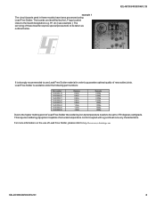
KDL-40V3000/46V3000/46VL130 It is available under the following part numbers : Part number 7-640-005-19 7-640-005-20 7-640-005-21 7-640-005-22 7-640-005-23 7-640-005-24 7-640-005-25 7-640-005-26 ... Free Solder. The boards are identified by the LF logo located close to guarantee optimal quality of Lead Free Solder, please refer to http://www.sony-training.com KDL-40V3000/46V3000/46VL130 8 Lead Free Solder is strongly recommended to use of new solder joints. example 1 The circuit boards used in order...
KDL-40V3000/46V3000/46VL130 It is available under the following part numbers : Part number 7-640-005-19 7-640-005-20 7-640-005-21 7-640-005-22 7-640-005-23 7-640-005-24 7-640-005-25 7-640-005-26 ... Free Solder. The boards are identified by the LF logo located close to guarantee optimal quality of Lead Free Solder, please refer to http://www.sony-training.com KDL-40V3000/46V3000/46VL130 8 Lead Free Solder is strongly recommended to use of new solder joints. example 1 The circuit boards used in order...
Service Manual
Page 9
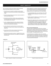
... Checking for cracks and abrasion. Check the line cords for earth ground. Leakage current can be measured by means of any exposed metal part to earth ground and from all the insulators. 4. A battery-operated AC milliampmeter. The Simpson's 250 and Sanwa SH-63TRD are "...pinched" or touching high-wattage resistors. 3. Nearly all other exposed metal parts for AC leakage. Try both slots, if necessary, to ensure that were installed during a previous repair. Check the area of deterioration. Check ...
... Checking for cracks and abrasion. Check the line cords for earth ground. Leakage current can be measured by means of any exposed metal part to earth ground and from all the insulators. 4. A battery-operated AC milliampmeter. The Simpson's 250 and Sanwa SH-63TRD are "...pinched" or touching high-wattage resistors. 3. Nearly all other exposed metal parts for AC leakage. Try both slots, if necessary, to ensure that were installed during a previous repair. Check the area of deterioration. Check ...
Service Manual
Page 22
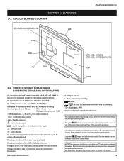
... taken with a color-bar signal input. The symbol indicates a fast operating fuse and is as marked. sont critiques pour la securite. Readings are DC with part number specified. symbol are in chip resistance. : nonflammable resistor : fusible resistor : internal component : panel designation and adjustment for safety. Les composants...
... taken with a color-bar signal input. The symbol indicates a fast operating fuse and is as marked. sont critiques pour la securite. Readings are DC with part number specified. symbol are in chip resistance. : nonflammable resistor : fusible resistor : internal component : panel designation and adjustment for safety. Les composants...
Service Manual
Page 74
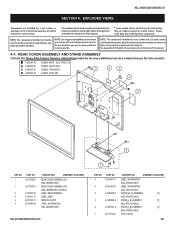
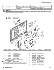
... description are not stocked because they are repaired and/or replaced. REAR COVER ASSEMBLY AND STAND ASSEMBLY (Check the Sony Electronics Service Information website for any additional service related issues for safety. PART NO. 1 X-2179-890-1 1 X-2179-891-1 2 3 4 * 5 3-106-918-01 3-106-917-...11 2-673-535-11 3-210-944-01 DESCRIPTION [ASSEMBLY INCLUDES] REAR COVER ASSEMBLY (40) (KDL-40V3000 ONLY) REAR COVER ASSEMBLY (46) (KDL...
... description are not stocked because they are repaired and/or replaced. REAR COVER ASSEMBLY AND STAND ASSEMBLY (Check the Sony Electronics Service Information website for any additional service related issues for safety. PART NO. 1 X-2179-890-1 1 X-2179-891-1 2 3 4 * 5 3-106-918-01 3-106-917-...11 2-673-535-11 3-210-944-01 DESCRIPTION [ASSEMBLY INCLUDES] REAR COVER ASSEMBLY (40) (KDL-40V3000 ONLY) REAR COVER ASSEMBLY (46) (KDL...
Service Manual
Page 75
sont critiques pour la securite. NO. CHASSIS (Check the Sony Electronics Service Information website for any additional service related issues for this manual. 4-2. NO. PART NO. 58 3-270-441-01 59 A-1433-191-A 60 A-1269-502-A DESCRIPTION [ASSEMBLY INCLUDES] COVER, MS (H) AU BOARD, COMPLETE ... (KDL-46V3000/46VL130 ONLY) 63 A-1226-204-B HW3 BOARD, MOUNTED 75 Ne les remplacer que par une piece portant le numero specifie. PART NO. 51 X-2176-664-1 52 A-1226-202-B 53 A-1253-586-B 54 X-2178-834-2 55 A-1256-640-A 61 DESCRIPTION [ASSEMBLY INCLUDES]...
sont critiques pour la securite. NO. CHASSIS (Check the Sony Electronics Service Information website for any additional service related issues for this manual. 4-2. NO. PART NO. 58 3-270-441-01 59 A-1433-191-A 60 A-1269-502-A DESCRIPTION [ASSEMBLY INCLUDES] COVER, MS (H) AU BOARD, COMPLETE ... (KDL-46V3000/46VL130 ONLY) 63 A-1226-204-B HW3 BOARD, MOUNTED 75 Ne les remplacer que par une piece portant le numero specifie. PART NO. 51 X-2176-664-1 52 A-1226-202-B 53 A-1253-586-B 54 X-2178-834-2 55 A-1256-640-A 61 DESCRIPTION [ASSEMBLY INCLUDES]...
Service Manual
Page 76
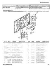
... for "Replacing the Inverter Connector Assembly" in the back of this manual. 4-3. PART NO. NO. Ne les remplacer que par une piece portant le numero specifie. CONNECTORS (Check the Sony Electronics Service Information website for any additional service related issues for this model, refer ...Appendix A: Encryption Key Components in the Disassembly section of this manual.) 104 1-910-039-02 EARTH CONNECTOR ASSEMBLY (HV2) 105 1-910-037-40 MO1929 CONNECTOR ASSEMBLY (BF) 20P 106 1-821-375-11 BOARD TO BOARD CONNECTOR 80P 107 1-821-376-11 BOARD TO BOARD CONNECTOR 50P...
... for "Replacing the Inverter Connector Assembly" in the back of this manual. 4-3. PART NO. NO. Ne les remplacer que par une piece portant le numero specifie. CONNECTORS (Check the Sony Electronics Service Information website for any additional service related issues for this model, refer ...Appendix A: Encryption Key Components in the Disassembly section of this manual.) 104 1-910-039-02 EARTH CONNECTOR ASSEMBLY (HV2) 105 1-910-037-40 MO1929 CONNECTOR ASSEMBLY (BF) 20P 106 1-821-375-11 BOARD TO BOARD CONNECTOR 80P 107 1-821-376-11 BOARD TO BOARD CONNECTOR 50P...
Service Manual
Page 77
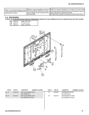
...649-01 2-580-606-01 SCREW, +BVTP2 4X16 +KTT 3X10 (S TYPE) SCREW, +PSW M5X8 152 152 151 REF. SPEAKERS (Check the Sony Electronics Service Information website for any additional service related issues for safety. NOTE: Les composants identifies per un trame et une marque !... LOUDSPEAKER (4.2X15CM) (KDL-40V3000 ONLY) LOUD SPEAKER (5.5X15.5CM) (KDL-46V3000/46VL130 ONLY) KDL-40V3000/46V3000/46VL130 77 Replace only with part number specified. Specific instructions must be adhered to whenever these components are critical for this manual. 4-4. mark are repaired and/...
...649-01 2-580-606-01 SCREW, +BVTP2 4X16 +KTT 3X10 (S TYPE) SCREW, +PSW M5X8 152 152 151 REF. SPEAKERS (Check the Sony Electronics Service Information website for any additional service related issues for safety. NOTE: Les composants identifies per un trame et une marque !... LOUDSPEAKER (4.2X15CM) (KDL-40V3000 ONLY) LOUD SPEAKER (5.5X15.5CM) (KDL-46V3000/46VL130 ONLY) KDL-40V3000/46V3000/46VL130 77 Replace only with part number specified. Specific instructions must be adhered to whenever these components are critical for this manual. 4-4. mark are repaired and/...
Service Manual
Page 78
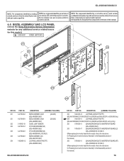
sont critiques pour la securite. BEZEL ASSEMBLY AND LCD PANEL (Check the Sony Electronics Service Information website for any additional service ... Disassembly section of this model.) 2-580-640-01 SCREW, +BVTP2 4X16 201 206 203 202 204 205 REF. PART NO. 201 X-2178-004-1 201 X-2178-005-1 202 3-198-631-01 203 X-2178-581-1 203 X-2178-582... ASSEMBLY(40) (KDL-40V3000 ONLY) SP COVER ASSEMBLY(46) (KDL-46V3000/46VL130 ONLY) BEZEL ASSEMBLY (46) (KDL-46VL130 ONLY) LCD PANEL (40INCH FHD TFT) (KDL-40V3000 ONLY) [202-203] [202-203] KDL-40V3000/46V3000/46VL130 REF. PART NO...
sont critiques pour la securite. BEZEL ASSEMBLY AND LCD PANEL (Check the Sony Electronics Service Information website for any additional service ... Disassembly section of this model.) 2-580-640-01 SCREW, +BVTP2 4X16 201 206 203 202 204 205 REF. PART NO. 201 X-2178-004-1 201 X-2178-005-1 202 3-198-631-01 203 X-2178-581-1 203 X-2178-582... ASSEMBLY(40) (KDL-40V3000 ONLY) SP COVER ASSEMBLY(46) (KDL-46V3000/46VL130 ONLY) BEZEL ASSEMBLY (46) (KDL-46VL130 ONLY) LCD PANEL (40INCH FHD TFT) (KDL-40V3000 ONLY) [202-203] [202-203] KDL-40V3000/46V3000/46VL130 REF. PART NO...
Service Manual
Page 79
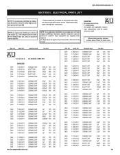
...routine service. Ne les remplacer que par une piece portant le numero specifie. * Items marked with part number specified. Specific instructions must be adhered to whenever these components. PART NO. DESCRIPTION VALUES AU A-1433-191-A AU BOARD, COMPLETE CAPACITOR C001 1-100-905-11 CERAMIC CHIP ...% 16V 2.2μF 10% 16V 2.2μF 100μF 1μF 220μF 47μF 10% 16V 20% 10V 10% 25V 20% 6.3V 20% 16V 79 PART NO. Expect some delay when ordering these components are in the back of this manual. KDL-40V3000/46V3000/46VL130 SECTION 5: ELECTRICAL...
...routine service. Ne les remplacer que par une piece portant le numero specifie. * Items marked with part number specified. Specific instructions must be adhered to whenever these components. PART NO. DESCRIPTION VALUES AU A-1433-191-A AU BOARD, COMPLETE CAPACITOR C001 1-100-905-11 CERAMIC CHIP ...% 16V 2.2μF 10% 16V 2.2μF 100μF 1μF 220μF 47μF 10% 16V 20% 10V 10% 25V 20% 6.3V 20% 16V 79 PART NO. Expect some delay when ordering these components are in the back of this manual. KDL-40V3000/46V3000/46VL130 SECTION 5: ELECTRICAL...
Service Manual
Page 82
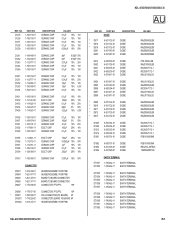
...-482-11 1-780-482-11 EARTH TERMINAL EARTH TERMINAL EARTH TERMINAL EARTH TERMINAL EARTH TERMINAL KDL-40V3000/46V3000/46VL130 82 C1235 C1236 C1237 C1238 C1239 PART NO. 1-100-916-11 1-100-916-11 1-100-916-11 1-100-916-11 1-100-905-11 DESCRIPTION CERAMIC CHIP CERAMIC CHIP CERAMIC CHIP CERAMIC CHIP...-21 CN1602 1-819-337-11 CONNECTOR, FFC/FPC 16P PIN, CONNECTOR (PC BOARD) 4P CONNECTOR, BOARD TO BOARD 6P HEADER ASSEMBLY FOR PWB REF. NO. PART NO. KDL-40V3000/46V3000/46VL130 AU REF.
...-482-11 1-780-482-11 EARTH TERMINAL EARTH TERMINAL EARTH TERMINAL EARTH TERMINAL EARTH TERMINAL KDL-40V3000/46V3000/46VL130 82 C1235 C1236 C1237 C1238 C1239 PART NO. 1-100-916-11 1-100-916-11 1-100-916-11 1-100-916-11 1-100-905-11 DESCRIPTION CERAMIC CHIP CERAMIC CHIP CERAMIC CHIP CERAMIC CHIP...-21 CN1602 1-819-337-11 CONNECTOR, FFC/FPC 16P PIN, CONNECTOR (PC BOARD) 4P CONNECTOR, BOARD TO BOARD 6P HEADER ASSEMBLY FOR PWB REF. NO. PART NO. KDL-40V3000/46V3000/46VL130 AU REF.
Service Manual
Page 91
...-11 CERAMIC CHIP CERAMIC CHIP CERAMIC CHIP KDL-40V3000/46V3000/46VL130 0.0047μF 10% 50V 0.47μF 10% 10V 0.01μF 10% 25V REF. NO. PART NO. mark are critical for safety. NOTE: Les composants identifies per un trame et une marque ! C6797 1-100-566-91 1-107-882-91... PIN, CONNECTOR (PC BOARD) 4P * CN6708 1-785-701-21 PIN, CONNECTOR (PC BOARD) 3P 91 Replace only with part number specified. NO. sont critiques pour la securite. VD457 VD458 VD459 VD460 PART NO. 1-802-090-21 1-802-090-21 1-802-090-21 1-802-090-21 DESCRIPTION VARISTOR, CHIP VARISTOR, CHIP...
...-11 CERAMIC CHIP CERAMIC CHIP CERAMIC CHIP KDL-40V3000/46V3000/46VL130 0.0047μF 10% 50V 0.47μF 10% 10V 0.01μF 10% 25V REF. NO. PART NO. mark are critical for safety. NOTE: Les composants identifies per un trame et une marque ! C6797 1-100-566-91 1-107-882-91... PIN, CONNECTOR (PC BOARD) 4P * CN6708 1-785-701-21 PIN, CONNECTOR (PC BOARD) 3P 91 Replace only with part number specified. NO. sont critiques pour la securite. VD457 VD458 VD459 VD460 PART NO. 1-802-090-21 1-802-090-21 1-802-090-21 1-802-090-21 DESCRIPTION VARISTOR, CHIP VARISTOR, CHIP...
Service Manual
Page 92
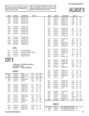
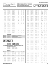
... specified. KDL-40V3000/46V3000/46VL130 DF1 REF. NO. PART NO. Ne les remplacer que par une piece portant le numero specifie. NOTE: The components identified by shading and ! sont critiques pour ...;H PQ200WNA1ZPH BA10339F-E2 MM1431ATT (CN) 68μH 2SB1122-S 2SB1122-S 2SB1122-S 2SB1122-S 2SK2009(TE85L) 2SC3052EF-T1-LEF 2SC3052EF-T1-LEF ISA1235AC1TP-1EF ISA1235AC1TP-1EF 92 NO. PART NO. DIODE D6600 D6601 D6604 D6605 D6606 6-501-818-01 6-501-818-01 6-501-497-01 6-501-497-01 6-501-497-01 DESCRIPTION DIODE DIODE...
... specified. KDL-40V3000/46V3000/46VL130 DF1 REF. NO. PART NO. Ne les remplacer que par une piece portant le numero specifie. NOTE: The components identified by shading and ! sont critiques pour ...;H PQ200WNA1ZPH BA10339F-E2 MM1431ATT (CN) 68μH 2SB1122-S 2SB1122-S 2SB1122-S 2SB1122-S 2SK2009(TE85L) 2SC3052EF-T1-LEF 2SC3052EF-T1-LEF ISA1235AC1TP-1EF ISA1235AC1TP-1EF 92 NO. PART NO. DIODE D6600 D6601 D6604 D6605 D6606 6-501-818-01 6-501-818-01 6-501-497-01 6-501-497-01 6-501-497-01 DESCRIPTION DIODE DIODE...
Service Manual
Page 94
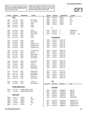
... specified. NO. R6789 R6790 R6792 R6793 R6794 PART NO. 1-218-887-11 1-218-883-11 1-216-837-11 1-216-833-11 1-218-871-11 DESCRIPTION METAL CHIP METAL CHIP METAL CHIP METAL CHIP .... Ne les remplacer que par une piece portant le numero specifie. T6800 ! NOTE: Les composants identifies per un trame et une marque ! PART NO.
... specified. NO. R6789 R6790 R6792 R6793 R6794 PART NO. 1-218-887-11 1-218-883-11 1-216-837-11 1-216-833-11 1-218-871-11 DESCRIPTION METAL CHIP METAL CHIP METAL CHIP METAL CHIP .... Ne les remplacer que par une piece portant le numero specifie. T6800 ! NOTE: Les composants identifies per un trame et une marque ! PART NO.


