Operation Manual
Page 3
... connected using tone signal detection, the regular DC180 V high-voltage power is displayed in down converter. Video inputs • Reference input (HD/SD support) • SDI return input, 2-system (HD/SD selectable) • VBS return input, 2-system • VBS prompter input, 2-system (HSCU300RF can be set to form a simple remote control system. Optical digital transmission (HSCU300RF) HD video signals can transfer only one selected VBS prompter input system to indicate cable open...
... connected using tone signal detection, the regular DC180 V high-voltage power is displayed in down converter. Video inputs • Reference input (HD/SD support) • SDI return input, 2-system (HD/SD selectable) • VBS return input, 2-system • VBS prompter input, 2-system (HSCU300RF can be set to form a simple remote control system. Optical digital transmission (HSCU300RF) HD video signals can transfer only one selected VBS prompter input system to indicate cable open...
Operation Manual
Page 4
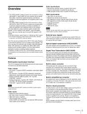
... enables support for RTS/Clear-Com systems, contact a Sony service or sales representative. Character monitor signal output The self-diagnosis status screens and setup menu can be installed in place of the front panel. Wide range of audio functions The CCU is 1.5U. See "Video outputs" on the CCU in a standard EIA 19-inch rack. It provides adjustment of basic functions using the operation switches and volume control. Rack...
... enables support for RTS/Clear-Com systems, contact a Sony service or sales representative. Character monitor signal output The self-diagnosis status screens and setup menu can be installed in place of the front panel. Wide range of audio functions The CCU is 1.5U. See "Video outputs" on the CCU in a standard EIA 19-inch rack. It provides adjustment of basic functions using the operation switches and volume control. Rack...

Operation Manual
Page 5
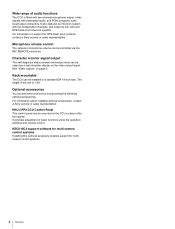
... Example (HSCU300RF, Optical Digital Transmission) Microphone HDVF-200/C35W Viewfinder HDVF-550/C550W/C730W Viewfinder Picture Monitor Waveform Monitor CAC-12 Microphone Holder Zoom Lens (for ENG/EFP) VCT-14 Tripod Adaptor Tripod for portable camera HSC300RF HSC100RF HD Color Camera VF attachment shoe b) Intercom headset Return video input Sync input Prompter video input BNC BNC Video router Optical fiber cable USB drive Power supply for a script light HSCU300RF Camera Control Unit Video output HD-SDI...
... Example (HSCU300RF, Optical Digital Transmission) Microphone HDVF-200/C35W Viewfinder HDVF-550/C550W/C730W Viewfinder Picture Monitor Waveform Monitor CAC-12 Microphone Holder Zoom Lens (for ENG/EFP) VCT-14 Tripod Adaptor Tripod for portable camera HSC300RF HSC100RF HD Color Camera VF attachment shoe b) Intercom headset Return video input Sync input Prompter video input BNC BNC Video router Optical fiber cable USB drive Power supply for a script light HSCU300RF Camera Control Unit Video output HD-SDI...
Operation Manual
Page 6
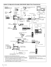
... HDVF-550/C550W/C730W Viewfinder Picture Monitor Waveform Monitor CAC-12 Microphone Holder Zoom Lens (for ENG/EFP) VCT-14 Tripod Adaptor Tripod for portable camera HSC300R HSC100R HSC-300 HXC-100 HD Color Camera VF attachment shoe b) Intercom headset Return video input Sync input Prompter video input BNC BNC Video router Triax cable c) USB drive Power supply for a script light HSCU300R Camera Control Unit Video output HD-SDI/SD-SDI/VBS...
... HDVF-550/C550W/C730W Viewfinder Picture Monitor Waveform Monitor CAC-12 Microphone Holder Zoom Lens (for ENG/EFP) VCT-14 Tripod Adaptor Tripod for portable camera HSC300R HSC100R HSC-300 HXC-100 HD Color Camera VF attachment shoe b) Intercom headset Return video input Sync input Prompter video input BNC BNC Video router Triax cable c) USB drive Power supply for a script light HSCU300R Camera Control Unit Video output HD-SDI/SD-SDI/VBS...

Operation Manual
Page 7
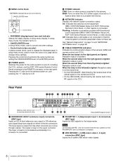
A number plate supplied with the CCU can be attached (see the following figure). c INTERCOM audio input/output and control block INTERCOM (intercom adjustment) knob MIC/PGM (microphone/program) switch INTERCOM (intercom select) switch PRIV indicator INTERCOM connector b CABLE ALARM indicators OPEN: Turns on when a camera is not connected (open circuit) to the camera. • INTERCOM (intercom adjustment) knob Adjusts the headset audio level. • MIC/PGM (microphone/program) switch ON: Turns the headset microphone on. While on...
A number plate supplied with the CCU can be attached (see the following figure). c INTERCOM audio input/output and control block INTERCOM (intercom adjustment) knob MIC/PGM (microphone/program) switch INTERCOM (intercom select) switch PRIV indicator INTERCOM connector b CABLE ALARM indicators OPEN: Turns on when a camera is not connected (open circuit) to the camera. • INTERCOM (intercom adjustment) knob Adjusts the headset audio level. • MIC/PGM (microphone/program) switch ON: Turns the headset microphone on. While on...
Operation Manual
Page 8
... position. e POWER switch Switches the power for the teleprompter. On: Indicates that external control equipment (MSU-1000/1500 Master Setup Unit, RCP-1000-series Remote Control Panel, or other device). When the two lamps on page 28. The input signal is output from the right (green) is lighted: Reception status is connected. It flashes when there is not connected or that a LAN cable is a problem with the external control equipment...
... position. e POWER switch Switches the power for the teleprompter. On: Indicates that external control equipment (MSU-1000/1500 Master Setup Unit, RCP-1000-series Remote Control Panel, or other device). When the two lamps on page 28. The input signal is output from the right (green) is lighted: Reception status is connected. It flashes when there is not connected or that a LAN cable is a problem with the external control equipment...

Operation Manual
Page 9
... format. It connects to the camera over a single optical fiber cable or triax cable. Note The HSCU300RF does not support SDI Prompter. e PIX (picture monitor output) connector (BNC type) Outputs a video signal for a waveform monitor. It can be configured as the HD/SD SDI Prompter input connector. p MIC/WF REMOTE/TRUNK (microphone/waveform monitor remote/trunk) connector (D-sub 25-pin) Supports the following functions. • Microphone remote Connects to an external control device, such as power...
... format. It connects to the camera over a single optical fiber cable or triax cable. Note The HSCU300RF does not support SDI Prompter. e PIX (picture monitor output) connector (BNC type) Outputs a video signal for a waveform monitor. It can be configured as the HD/SD SDI Prompter input connector. p MIC/WF REMOTE/TRUNK (microphone/waveform monitor remote/trunk) connector (D-sub 25-pin) Supports the following functions. • Microphone remote Connects to an external control device, such as power...

Operation Manual
Page 10
... Setup Unit or RCP-1000-series Remote Control Panel). e SHUTTER controls Controls the shutter settings. When the ON button is lit: Displays the shutter speed. • UP/DOWN lever When the ECS button is lit: Adjusts the shutter speed. When the ON button is lit: Adjusts the clear scan frequency. f MASTER GAIN controls Controls the video output signal gain in the CCU CONFIGURATION menu. The button light turns on the page in response to the lighting of Parts Display...
... Setup Unit or RCP-1000-series Remote Control Panel). e SHUTTER controls Controls the shutter settings. When the ON button is lit: Displays the shutter speed. • UP/DOWN lever When the ECS button is lit: Adjusts the shutter speed. When the ON button is lit: Adjusts the clear scan frequency. f MASTER GAIN controls Controls the video output signal gain in the CCU CONFIGURATION menu. The button light turns on the page in response to the lighting of Parts Display...

Operation Manual
Page 11
... the page in the CCU CONFIGURATION menu. Note When the ATW button is black balance adjustment in response to the input light level. The indicator operating mode (on/off ). The adjustment can be automatically adjusted using the AUTO WHITE/BLACK lever. • When the BLACK/FLARE indicator is automatically adjusted in relative value mode. • MASTER BLACK (master black adjustment) knob Adjusts the master black manually. j White balance adjustment controls ATW (auto tracing white balance) button WHITE (white balance manual adjustment) knobs See "R/B BLACK" on page 26 on "" and...
... the page in the CCU CONFIGURATION menu. Note When the ATW button is black balance adjustment in response to the input light level. The indicator operating mode (on/off ). The adjustment can be automatically adjusted using the AUTO WHITE/BLACK lever. • When the BLACK/FLARE indicator is automatically adjusted in relative value mode. • MASTER BLACK (master black adjustment) knob Adjusts the master black manually. j White balance adjustment controls ATW (auto tracing white balance) button WHITE (white balance manual adjustment) knobs See "R/B BLACK" on page 26 on "" and...

Operation Manual
Page 12
... • Camera hardware diagnostics • ROM version Information Camera settings Page 1 a b cd 6dB 1/2000 OFF ND:1 F:4.7 EX CC:A e fg h a Master gain value Video output signal gain (dB units) b Shutter speed/Clear scan frequency Shutter speed value. The most recently viewed status screen page is displayed (when first powered on page 16. For information on monitoring and changing settings, see "Setup Menu" on , the camera settings page is displayed). Status Display The CCU...
... • Camera hardware diagnostics • ROM version Information Camera settings Page 1 a b cd 6dB 1/2000 OFF ND:1 F:4.7 EX CC:A e fg h a Master gain value Video output signal gain (dB units) b Shutter speed/Clear scan frequency Shutter speed value. The most recently viewed status screen page is displayed (when first powered on page 16. For information on monitoring and changing settings, see "Setup Menu" on , the camera settings page is displayed). Status Display The CCU...
Operation Manual
Page 13
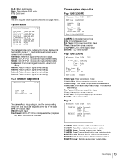
... Type Digital Cable Connect Comp. Auto Step 4 Fan Power OK Timer 96H CCU Power AC OK SerialNo 100001 TRIAX Type: Triax transmission mode TRIAX Cable: CCU triax cable connection status TRIAX Comp.: Triax cable compensation mode selection TRIAX Step: Triax cable compensation step (internal circuit step display) Fan Power: CCU power supply fan status Timer: Elapsed time since power-on CCU Power: CCU power supply type and status SerialNo: CCU serial number Page 2 *System Diag 2/3* 4/13 CAMERA REMOTE Cable Connect Data...
... Type Digital Cable Connect Comp. Auto Step 4 Fan Power OK Timer 96H CCU Power AC OK SerialNo 100001 TRIAX Type: Triax transmission mode TRIAX Cable: CCU triax cable connection status TRIAX Comp.: Triax cable compensation mode selection TRIAX Step: Triax cable compensation step (internal circuit step display) Fan Power: CCU power supply fan status Timer: Elapsed time since power-on CCU Power: CCU power supply type and status SerialNo: CCU serial number Page 2 *System Diag 2/3* 4/13 CAMERA REMOTE Cable Connect Data...
Operation Manual
Page 16
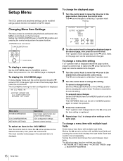
... control knob. Turning the control knob moves the cursor between input fields. The ? To change other settings on the same page. To display the CCU MENU page In menu display mode, turn the control knob to move the , arrow to the PIX output. Flashing ?S01 TOP OUTPUT:*CAMERA BAR TEST1 TEST2 PIX:*ENC R&G WF :*ENC R&G R G B G&B R&B RGB R G B SEQ G&B R&B RGB 2 Turn the control knob to change a menu item setting If a ? Changing Menu Item Settings The menu screen is controlled using a picture monitor connected...
... control knob. Turning the control knob moves the cursor between input fields. The ? To change other settings on the same page. To display the CCU MENU page In menu display mode, turn the control knob to move the , arrow to the PIX output. Flashing ?S01 TOP OUTPUT:*CAMERA BAR TEST1 TEST2 PIX:*ENC R&G WF :*ENC R&G R G B G&B R&B RGB R G B SEQ G&B R&B RGB 2 Turn the control knob to change a menu item setting If a ? Changing Menu Item Settings The menu screen is controlled using a picture monitor connected...

Operation Manual
Page 18
... CH2 MIC REMOTE MIC OUT DELAY MIC1 LEVEL MIC2 LEVEL CAMERA SYSTEM I/F TERMINATION PGM1 INPUT PGM2 INPUT INCOM MIC MIC TYPE MIC GAIN SIDE TONE PGM MIX PGM SEL PGM1 LVL PGM2 LVL MODE TRANSFER INPUT SETUP Q FILTER SD G/Y SYNC WF SYNC VBS LEVEL CHROMA PIX LEVEL CHROMA WF LEVEL CHROMA COMPONENT LEVEL MENU SETTINGS (C11) DISPLAY (C12) DATE (C13) OTHERS (C14) FRONT PANEL 1 (C15) FRONT PANEL 2 (C16) RESUME RE DIRECTION CATEGORY PAGE ITEM DATA MESSAGE ALARM...
... CH2 MIC REMOTE MIC OUT DELAY MIC1 LEVEL MIC2 LEVEL CAMERA SYSTEM I/F TERMINATION PGM1 INPUT PGM2 INPUT INCOM MIC MIC TYPE MIC GAIN SIDE TONE PGM MIX PGM SEL PGM1 LVL PGM2 LVL MODE TRANSFER INPUT SETUP Q FILTER SD G/Y SYNC WF SYNC VBS LEVEL CHROMA PIX LEVEL CHROMA WF LEVEL CHROMA COMPONENT LEVEL MENU SETTINGS (C11) DISPLAY (C12) DATE (C13) OTHERS (C14) FRONT PANEL 1 (C15) FRONT PANEL 2 (C16) RESUME RE DIRECTION CATEGORY PAGE ITEM DATA MESSAGE ALARM...

Operation Manual
Page 22
... display on/off and signal level setting ---: Displayed when camera not connected (read only) 4:3 aspect ratio mask function on/off when EDGE CROP is ON, and mask video level setting ---: Displayed when camera not connected (read only) Marker signal on/off and superimposed signal selection Camera microphone gain settings (REMOTE): MIC REMOTE source (LOCAL): Not MIC REMOTE source Set to match the microphone used. ---: Displayed when camera not connected (read only) MIC REMOTE gain control method MIC 1&2: MIC 1, 2 common gain control MIC 1.2: MIC 1, 2 independent gain control...
... display on/off and signal level setting ---: Displayed when camera not connected (read only) 4:3 aspect ratio mask function on/off when EDGE CROP is ON, and mask video level setting ---: Displayed when camera not connected (read only) Marker signal on/off and superimposed signal selection Camera microphone gain settings (REMOTE): MIC REMOTE source (LOCAL): Not MIC REMOTE source Set to match the microphone used. ---: Displayed when camera not connected (read only) MIC REMOTE gain control method MIC 1&2: MIC 1, 2 common gain control MIC 1.2: MIC 1, 2 independent gain control...

Operation Manual
Page 23
... condenser microphone (power supply, 40 dB gain) DYNAMIC: Dynamic microphone (no power supply, 60 dB gain) Headset microphone type connected to INTERCOM on the front panel BALANCE: Balanced microphone UNBALANCE: Unbalanced microphone Input gain setting Side tone level setting OFF: PGM MIX disabled INCOM+PGM: INCOM and PGM mixing L-INCOM/R-PGM: INCOM output on left and PGM output on right PGM output settings PGM1 level setting PGM2 level setting Video resolution mode switch (HSCU300R only) NORMAL: Color picture transmitted...
... condenser microphone (power supply, 40 dB gain) DYNAMIC: Dynamic microphone (no power supply, 60 dB gain) Headset microphone type connected to INTERCOM on the front panel BALANCE: Balanced microphone UNBALANCE: Unbalanced microphone Input gain setting Side tone level setting OFF: PGM MIX disabled INCOM+PGM: INCOM and PGM mixing L-INCOM/R-PGM: INCOM output on left and PGM output on right PGM output settings PGM1 level setting PGM2 level setting Video resolution mode switch (HSCU300R only) NORMAL: Color picture transmitted...

Operation Manual
Page 24
... Setup Menu Displayed on /off . MESSAGE ALARM JUMP MASTER GAIN ECS/SHUTTER ND FILTER CC FILTER C13 IRIS EXTENDER DATE/TIME TIME ZONE ALL, WARNING, OFF ON, OFF ON, OFF ON, OFF ON, OFF ON, OFF ON, OFF ON, OFF 20YY/MM/DD hh:mm hh:mm Indication VBS output video level adjustment PIX output video level adjustment WF output video level adjustment Component signal level setting In menu mode, resume display of previously displayed page function control...
... Setup Menu Displayed on /off . MESSAGE ALARM JUMP MASTER GAIN ECS/SHUTTER ND FILTER CC FILTER C13 IRIS EXTENDER DATE/TIME TIME ZONE ALL, WARNING, OFF ON, OFF ON, OFF ON, OFF ON, OFF ON, OFF ON, OFF ON, OFF 20YY/MM/DD hh:mm hh:mm Indication VBS output video level adjustment PIX output video level adjustment WF output video level adjustment Component signal level setting In menu mode, resume display of previously displayed page function control...
Operation Manual
Page 28
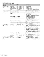
... multi-camera control system support software is displayed. Network connection mode selection LEGACY: External controller connected using CCA-5 cable only BRIDGE: External controller connected using point-to confirm the change . Press ENTER again to reset NETWORK SETTINGS menu items to execute Indication IP address setting Subnet mask display Default gateway display A "SET OK?" message is installed.) Multi-camera system configuration of connection speed and communication mode with connected device Connection speed selection 10M: 10BASE-TX 100M: 100BASE-TX Configurable only when AUTO...
... multi-camera control system support software is displayed. Network connection mode selection LEGACY: External controller connected using CCA-5 cable only BRIDGE: External controller connected using point-to confirm the change . Press ENTER again to reset NETWORK SETTINGS menu items to execute Indication IP address setting Subnet mask display Default gateway display A "SET OK?" message is installed.) Multi-camera system configuration of connection speed and communication mode with connected device Connection speed selection 10M: 10BASE-TX 100M: 100BASE-TX Configurable only when AUTO...

Operation Manual
Page 29
... of the unit and/or inside of the unit. For details on parts replacement, contact your dealer. For severe dirt, use Set the POWER switch on the CCU to a malfunction. This is guaranteed. distance 50 m...MIC 1 and 2 audio signals from the CCU to match the video delay. • A certain time is required for the video signal transmitted between the camera and the CCU to the camera from the CCU) and cable degradation. distance1) Min. Digital Triax Transmission (HSCU300R) Digital transmission between 100 and 120 W. Allowable transmission range when using simplified images...
... of the unit and/or inside of the unit. For details on parts replacement, contact your dealer. For severe dirt, use Set the POWER switch on the CCU to a malfunction. This is guaranteed. distance 50 m...MIC 1 and 2 audio signals from the CCU to match the video delay. • A certain time is required for the video signal transmitted between the camera and the CCU to the camera from the CCU) and cable degradation. distance1) Min. Digital Triax Transmission (HSCU300R) Digital transmission between 100 and 120 W. Allowable transmission range when using simplified images...

Operation Manual
Page 30
... an error message is displayed on the CCU. Please contact MPEG LA for example) Max. Cable (for any storage media storing MPEG-2 video information such as DVD movie which are sold/ distributed to REMOTE connector) power supply error Transmission error between camera and CCU License Declarations The CCU teleprompter video circuit uses MPEG-2 technology. Disc replicators or sellers of the PACKAGED MEDIA need to 240 V SDI RETURN 1, 2 BNC type...
... an error message is displayed on the CCU. Please contact MPEG LA for example) Max. Cable (for any storage media storing MPEG-2 video information such as DVD movie which are sold/ distributed to REMOTE connector) power supply error Transmission error between camera and CCU License Declarations The CCU teleprompter video circuit uses MPEG-2 technology. Disc replicators or sellers of the PACKAGED MEDIA need to 240 V SDI RETURN 1, 2 BNC type...

Operation Manual
Page 31
...;) MIC OUT XLR 3-pin, male (2), 0 dBu / -20 dBu Supplied accessories Number plates (1 set) Operation guide (1) Operation manual (CD-ROM) (1) Optional accessories HKCU-FP2 CCU Control Panel HZCU-MC3 Camera Operating Software United States and Canada: Plug holder B (2-990-242-01) Other areas: Plug holder C (3-613-640-01) United States and Canada: Power cord set (1-551-812-XX) Other areas: Power cord set (1-782-929-XX) CCA-5-3 (3 m), CCA-5-10 (10 m) connection cables Maintenance manual...
...;) MIC OUT XLR 3-pin, male (2), 0 dBu / -20 dBu Supplied accessories Number plates (1 set) Operation guide (1) Operation manual (CD-ROM) (1) Optional accessories HKCU-FP2 CCU Control Panel HZCU-MC3 Camera Operating Software United States and Canada: Plug holder B (2-990-242-01) Other areas: Plug holder C (3-613-640-01) United States and Canada: Power cord set (1-551-812-XX) Other areas: Power cord set (1-782-929-XX) CCA-5-3 (3 m), CCA-5-10 (10 m) connection cables Maintenance manual...

