Operation Manual
Page 6
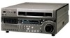
... recording formats. HDCAM format The HDCAM format uses the same 12.65-mm width tape as standard equipment, for playback compatibility with SMPTE 305M, and can also play back tapes recorded in a compact (4U size), lightweight, and low power consumption design. In addition to HDCAM playback heads, the unit is supported. The audio signals are based on AES/EBU format, and are loaded, so that no menu settings need to digital...
... recording formats. HDCAM format The HDCAM format uses the same 12.65-mm width tape as standard equipment, for playback compatibility with SMPTE 305M, and can also play back tapes recorded in a compact (4U size), lightweight, and low power consumption design. In addition to HDCAM playback heads, the unit is supported. The audio signals are based on AES/EBU format, and are loaded, so that no menu settings need to digital...

Operation Manual
Page 7
... be selected to be set from an external remote controller or editor through an interface complying with external devices, can be output even when playing back tapes recorded in formats other than HDCAM. Time data display This can mount the unit in the conventional VTR layout, ensuring continuity with conventional operating panels. High quality variable speed playback and digital jog sound function In HDCAM format playback, the dedicated playback DT heads allow...
... be selected to be set from an external remote controller or editor through an interface complying with external devices, can be output even when playing back tapes recorded in formats other than HDCAM. Time data display This can mount the unit in the conventional VTR layout, ensuring continuity with conventional operating panels. High quality variable speed playback and digital jog sound function In HDCAM format playback, the dedicated playback DT heads allow...
Operation Manual
Page 10
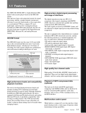
.../SP BETACAM SX MPEG IMX Digital BETACAM HDCAM 5 PHONES jack and control Cassette compartment 1 POWER switch Pressing the ' ) ' side of Parts 4 Format indicators The indicator (BETACAM/SP, BETACAM SX, MPEG IMX, Digital BETACAM, or HDCAM) corresponding to the Installation Manual. The control knob adjusts the volume. When using the lower control panel as remote control panel, press the DELETE button and STOP button at the same time to the REMOTE 1-IN(9P...
.../SP BETACAM SX MPEG IMX Digital BETACAM HDCAM 5 PHONES jack and control Cassette compartment 1 POWER switch Pressing the ' ) ' side of Parts 4 Format indicators The indicator (BETACAM/SP, BETACAM SX, MPEG IMX, Digital BETACAM, or HDCAM) corresponding to the Installation Manual. The control knob adjusts the volume. When using the lower control panel as remote control panel, press the DELETE button and STOP button at the same time to the REMOTE 1-IN(9P...
Operation Manual
Page 13
... control knobs and adjust the level while monitoring the audio level indication on channels 1 to F6: Make settings for the corresponding item and displays the setting in the order HOME t 1 t 2 t 3 t 4 t HOME. During playback, press to the MONITOR OUTPUT L connector. The page buttons (V, v, and HOME) select menu pages, and the function buttons (F1 to the MONITOR OUTPUT L and R connectors on the connector panel or the PHONES jack...
... control knobs and adjust the level while monitoring the audio level indication on channels 1 to F6: Make settings for the corresponding item and displays the setting in the order HOME t 1 t 2 t 3 t 4 t HOME. During playback, press to the MONITOR OUTPUT L connector. The page buttons (V, v, and HOME) select menu pages, and the function buttons (F1 to the MONITOR OUTPUT L and R connectors on the connector panel or the PHONES jack...
Operation Manual
Page 15
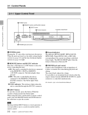
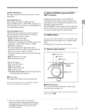
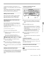
... menu display section. Chapter 2 Location and Function of Parts However, CONFI playback is displayed in time data display area 1, hold this state, the value of the detected tape diameter. Depending on the setting of seconds. "DOLBY" and the double-D symbol ; REM: Remaining time on function menu page 3, either TOTL (TOTAL) or REM (REMAIN) is functioning. Resetting the CTL value erases all edit points. 7 Search control section 1 SHUTTLE button 2 JOG button...
... menu display section. Chapter 2 Location and Function of Parts However, CONFI playback is displayed in time data display area 1, hold this state, the value of the detected tape diameter. Depending on the setting of seconds. "DOLBY" and the double-D symbol ; REM: Remaining time on function menu page 3, either TOTL (TOTAL) or REM (REMAIN) is functioning. Resetting the CTL value erases all edit points. 7 Search control section 1 SHUTTLE button 2 JOG button...
Operation Manual
Page 16
... normal speed position. Turning the dial counterclockwise lights the h indicator and plays back in the forward direction. HDCAM: -1 to +2 times normal speed Digital Betacam: -1 to +3 times normal speed MPEG IMX: -1 to +3 times normal speed Betacam SX: -1 to +2 times normal speed Betacam/Betacam SP: -1 to show the current search mode or the mode used last. Playback is lit to +3 times normal speed Playback modes using the search dial Playback mode Operations and functions Shuttle Press the SHUTTLE button or...
... normal speed position. Turning the dial counterclockwise lights the h indicator and plays back in the forward direction. HDCAM: -1 to +2 times normal speed Digital Betacam: -1 to +3 times normal speed MPEG IMX: -1 to +3 times normal speed Betacam SX: -1 to +2 times normal speed Betacam/Betacam SP: -1 to show the current search mode or the mode used last. Playback is lit to +3 times normal speed Playback modes using the search dial Playback mode Operations and functions Shuttle Press the SHUTTLE button or...
Operation Manual
Page 17
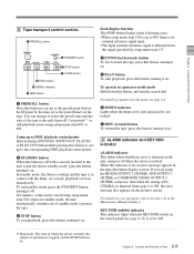
... standby mode, press the button, turning it off when the error is set to put the unit in function menu page 4 is different from the signal specified by the time set as the preroll time) on the tape. Chapter 2 Location and Function of Parts 8 Tape transport control section 1 PREROLL button PREROLL REW PLAY STANDBY 2 STANDBY button F FWD STOP 3 STOP button 4 F FWD button 5 PLAY button 6 SERVO indicator 7 REW button 1 PREROLL button Press this button, turning it on. Fault display function The STOP button flashes...
... standby mode, press the button, turning it off when the error is set to put the unit in function menu page 4 is different from the signal specified by the time set as the preroll time) on the tape. Chapter 2 Location and Function of Parts 8 Tape transport control section 1 PREROLL button PREROLL REW PLAY STANDBY 2 STANDBY button F FWD STOP 3 STOP button 4 F FWD button 5 PLAY button 6 SERVO indicator 7 REW button 1 PREROLL button Press this button, turning it on. Fault display function The STOP button flashes...
Operation Manual
Page 20
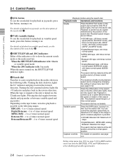
... connection cable. 4 PANEL SELECT switch In addition to the lower control panel, you can connect a similar control panel to this to update the firmware. When setup menu item 117 is used to specify which buttons and knobs are connected to the unit, the PANEL SELECT switch is set to PARA, this switch position also enables the control panel connected to eject a memory card from the memory card slot. 3 CONTROL PANEL connector (10-pin, round type) Plug...
... connection cable. 4 PANEL SELECT switch In addition to the lower control panel, you can connect a similar control panel to this to update the firmware. When setup menu item 117 is used to specify which buttons and knobs are connected to the unit, the PANEL SELECT switch is set to PARA, this switch position also enables the control panel connected to eject a memory card from the memory card slot. 3 CONTROL PANEL connector (10-pin, round type) Plug...
Operation Manual
Page 24
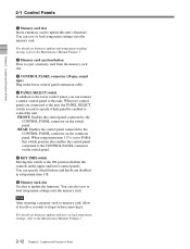
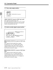
... for output. 2 MONITOR OUTPUT L connector (XLR 3-pin, male) This outputs the audio signals whose output destination was set to 'L' with the audio signal selection buttons in the audio control section. By setting setup menu item 606, you can also output the time code from the internal time code generator locked to the playback time code. 8 Audio monitor signal output section MONITOR OUTPUT R L 1 MONITOR OUTPUT R connector 2 MONITOR OUTPUT...
... for output. 2 MONITOR OUTPUT L connector (XLR 3-pin, male) This outputs the audio signals whose output destination was set to 'L' with the audio signal selection buttons in the audio control section. By setting setup menu item 606, you can also output the time code from the internal time code generator locked to the playback time code. 8 Audio monitor signal output section MONITOR OUTPUT R L 1 MONITOR OUTPUT R connector 2 MONITOR OUTPUT...
Operation Manual
Page 35
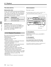
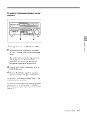
...; Playback using the capstan override function The playback speed is possible to disable the automatic rewind function by the internal time code generator (REGEN), or the playback time code (TAPE). For details of CTL (control), time code, and user bit values. Cassette compartment Z Output time code The setting of setup menu item 606 determines whether the time code output from the TIME CODE OUT connector is automatically rewound, and stops. STOP button PLAY button 4-1-2 Playback Procedures This section describes the following types of the tape The tape...
...; Playback using the capstan override function The playback speed is possible to disable the automatic rewind function by the internal time code generator (REGEN), or the playback time code (TAPE). For details of CTL (control), time code, and user bit values. Cassette compartment Z Output time code The setting of setup menu item 606 determines whether the time code output from the TIME CODE OUT connector is automatically rewound, and stops. STOP button PLAY button 4-1-2 Playback Procedures This section describes the following types of the tape The tape...
Operation Manual
Page 38
... of character information displayed on the monitor screen. 3 Press the PLAY button while holding down the DMC EDIT button and turn the MULTI CONTROL knob to exit the tape speed override mode. The selected playback speed is displayed in time data display area 2 on the lower control panel of this unit as well as in function menu page 4 (page 8-6) and setup menu item 005 (page 9-7). 4-5 Chapter 4 Playback Chapter 4 Playback See Section 9-2 "Setup Menu Operations" (page 9-2) for...
... of character information displayed on the monitor screen. 3 Press the PLAY button while holding down the DMC EDIT button and turn the MULTI CONTROL knob to exit the tape speed override mode. The selected playback speed is displayed in time data display area 2 on the lower control panel of this unit as well as in function menu page 4 (page 8-6) and setup menu item 005 (page 9-7). 4-5 Chapter 4 Playback Chapter 4 Playback See Section 9-2 "Setup Menu Operations" (page 9-2) for...
Operation Manual
Page 42
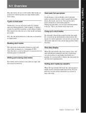
... and erasing shot marks Post marks can therefore sort the read-in memory (to the list. Shot data display When the tape includes shot data (camera, time, and other information captured at any point on a tape and stores them in shot marks by a button operation during playback, while stopped, or during a search. This chapter describes the use of shot marks. During tape playback...
... and erasing shot marks Post marks can therefore sort the read-in memory (to the list. Shot data display When the tape includes shot data (camera, time, and other information captured at any point on a tape and stores them in shot marks by a button operation during playback, while stopped, or during a search. This chapter describes the use of shot marks. During tape playback...
Operation Manual
Page 46
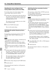
... change the cassette or power the unit off, it will be read in . Repeat this operation to be deleted. While you hold down . In item G02 of the menu, see page 5-2. To delete the entire list Hold down the MARK button turn the MULTI CONTROL knob to "ON". For details of the shot mark operation menu, set the required types to select all shot marks from the tape. Deleting...
... change the cassette or power the unit off, it will be read in . Repeat this operation to be deleted. While you hold down . In item G02 of the menu, see page 5-2. To delete the entire list Hold down the MARK button turn the MULTI CONTROL knob to "ON". For details of the shot mark operation menu, set the required types to select all shot marks from the tape. Deleting...
Operation Manual
Page 74
... menu settings. The next time the unit is turned on, it will operate in 59.94i, 29.97PsF mode only. The next time the unit is valid in the new mode. Notes • Before carrying out this operation, consult the person responsible for system installation. • When the unit is used in 50i, 25PsF mode, analog tape can only be played back in the simple playback mode...
... menu settings. The next time the unit is turned on, it will operate in 59.94i, 29.97PsF mode only. The next time the unit is valid in the new mode. Notes • Before carrying out this operation, consult the person responsible for system installation. • When the unit is used in 50i, 25PsF mode, analog tape can only be played back in the simple playback mode...
Operation Manual
Page 78
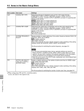
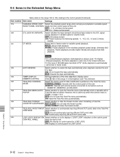
... monitor. Notes • For the basic and extended setup menus, separate settings are different from the settings for the mode before switching.) • When the unit is used in 50i, 25PsF mode, analog tape can only be played back in the simple playback mode. 018 ACTIVE LINE SELECT Enable or disable switching of the number of active scan lines for HDSDI output (Valid only in...
... monitor. Notes • For the basic and extended setup menus, separate settings are different from the settings for the mode before switching.) • When the unit is used in 50i, 25PsF mode, analog tape can only be played back in the simple playback mode. 018 ACTIVE LINE SELECT Enable or disable switching of the number of active scan lines for HDSDI output (Valid only in...
Operation Manual
Page 80
... : Flash the STOP button as a warning. 106 CAPSTAN LOCK Select the capstan servo lock mode. Maximum fast forward and rewind speeds HDCAM cassette: 50 times normal speed Maximum search mode speeds HDCAM cassette: 50 times normal speed 103 AUDIO SELECTED LINE Select the output signal to 24 times normal speed. ×35: Perform fast forward and rewind at 35 times normal speed, and search mode playback at all times except during editing. DIAL : Turning the search dial switches to...
... : Flash the STOP button as a warning. 106 CAPSTAN LOCK Select the capstan servo lock mode. Maximum fast forward and rewind speeds HDCAM cassette: 50 times normal speed Maximum search mode speeds HDCAM cassette: 50 times normal speed 103 AUDIO SELECTED LINE Select the output signal to 24 times normal speed. ×35: Perform fast forward and rewind at 35 times normal speed, and search mode playback at all times except during editing. DIAL : Turning the search dial switches to...
Operation Manual
Page 82
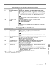
...: Do not rewind the tape automatically. MODE CONTROL PANEL : Operate with remote devices connected to connectors such as REMOTE1, REMOTE2, and RS-232C. 134 TELE-FILE MENU AUTO Select whether to continuously input log (IN and OUT point) data in the noiseless playback speed range; REMOTE: Operate with the control panel of the time data/menu display panel. COUNTER CLEAR MODE NOT CLEAR : Do not clear the thread counter. WHEN FORMAT: Clear the thread...
...: Do not rewind the tape automatically. MODE CONTROL PANEL : Operate with remote devices connected to connectors such as REMOTE1, REMOTE2, and RS-232C. 134 TELE-FILE MENU AUTO Select whether to continuously input log (IN and OUT point) data in the noiseless playback speed range; REMOTE: Operate with the control panel of the time data/menu display panel. COUNTER CLEAR MODE NOT CLEAR : Do not clear the thread counter. WHEN FORMAT: Clear the thread...
Operation Manual
Page 85
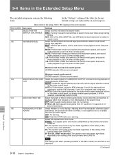
... 23.98PsF mode, and this item is not displayed. 338 OUTPUT AUDIO/TC Set the audio (AES/EBU and analog) and time code output phase. PHASE HD : Sync with SD output phase. SD : Sync with HDSDI output phase. Menu items in the range 300 to 399, relating to editing operations (Continued) Item number Item name Settings 337 EXTERNAL REFERENCE Select the signal used when...
... 23.98PsF mode, and this item is not displayed. 338 OUTPUT AUDIO/TC Set the audio (AES/EBU and analog) and time code output phase. PHASE HD : Sync with SD output phase. SD : Sync with HDSDI output phase. Menu items in the range 300 to 399, relating to editing operations (Continued) Item number Item name Settings 337 EXTERNAL REFERENCE Select the signal used when...
Operation Manual
Page 100
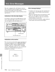
... appear in the time data display. • Error messages with a self-diagnosis function, and if a problem is slightly different on the monitor and in the time data display. If an error message appears, contact your Sony service representative. 10-3 Error Messages This unit is equipped with error codes are saved in nonvolatile memory as a secondary error message. Z ALARM indicator Time data display area 1 Indications on the monitor The error message and code also appear superimposed...
... appear in the time data display. • Error messages with a self-diagnosis function, and if a problem is slightly different on the monitor and in the time data display. If an error message appears, contact your Sony service representative. 10-3 Error Messages This unit is equipped with error codes are saved in nonvolatile memory as a secondary error message. Z ALARM indicator Time data display area 1 Indications on the monitor The error message and code also appear superimposed...
Operation Manual
Page 111
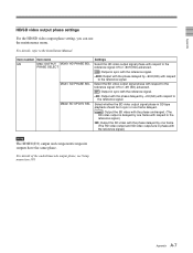
Item number Item name M3 M3A: OUTPUT M3A0: HD PHASE SEL PHASE SELECT M3A1: SD PHASE SEL M3A2: SD UPCNV SEL Settings Select the HD video output signal phase with respect ... have the same phase. For details of the audio/timecode output phase, see Setup menu item 338. Select whether the SD video output signal phase in SD tape playback should be in sync or one frame. (The...signal. Appendix HD/SD video output phase settings For the HD/SD video output phase setting, you can use the maintenance menu. Select the SD video output signal phase with respect to the Installation Manual.
Item number Item name M3 M3A: OUTPUT M3A0: HD PHASE SEL PHASE SELECT M3A1: SD PHASE SEL M3A2: SD UPCNV SEL Settings Select the HD video output signal phase with respect ... have the same phase. For details of the audio/timecode output phase, see Setup menu item 338. Select whether the SD video output signal phase in SD tape playback should be in sync or one frame. (The...signal. Appendix HD/SD video output phase settings For the HD/SD video output phase setting, you can use the maintenance menu. Select the SD video output signal phase with respect to the Installation Manual.


