Operation Manual
Page 7
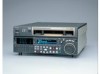
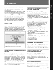
... equipped with existing recording formats. The audio signals are based on the HDCAM format. 1-1 Features Chapter 1Chapter 1 Overview Overview The HDW-2000/M2000/M2000P is supported. Multifunction control panel While built in narrow tracks with Betacam SX playback heads and analog Betacam DT heads, for ...video/ audio data) (Option) • Time code input/output • CUE audio input/output High quality four-channel audio High quality 20 bit/48 kHz AES/EBU digital audio is a high-definition (HD) digital videocassette recorder based on AES/EBU format, and are four digital...
... equipped with existing recording formats. The audio signals are based on the HDCAM format. 1-1 Features Chapter 1Chapter 1 Overview Overview The HDW-2000/M2000/M2000P is supported. Multifunction control panel While built in narrow tracks with Betacam SX playback heads and analog Betacam DT heads, for ...video/ audio data) (Option) • Time code input/output • CUE audio input/output High quality four-channel audio High quality 20 bit/48 kHz AES/EBU digital audio is a high-definition (HD) digital videocassette recorder based on AES/EBU format, and are four digital...
Operation Manual
Page 8
... it by the same type of operations such as standard equipment. Wide range of operation as for a conventional analog VTR. Upward converter function (HDW-M2000/ M2000P only) The HDW-M2000/M2000P features a standard definition to high definition (SD-to easily change settings. You can carry out both assemble editing and insert editing automatically. It...
... it by the same type of operations such as standard equipment. Wide range of operation as for a conventional analog VTR. Upward converter function (HDW-M2000/ M2000P only) The HDW-M2000/M2000P features a standard definition to high definition (SD-to easily change settings. You can carry out both assemble editing and insert editing automatically. It...
Operation Manual
Page 10
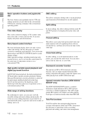
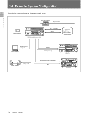
Digital cassette BVE-series editor Tape control HDW-2000/M2000/M2000P SDTI (optional) HDSDI Audio/video server system HDSDI/Analog composite Video monitor Audio monitor Analog audio HDSDI SDTI (optional) Analog composite/component SDI HD VTR SD VTR 1-4 Chapter 1 Overview Chapter 1 Overview 1-11 -F2eaEtuxreasmple System Configuration The following conceptual diagram shows an example of use.
Digital cassette BVE-series editor Tape control HDW-2000/M2000/M2000P SDTI (optional) HDSDI Audio/video server system HDSDI/Analog composite Video monitor Audio monitor Analog audio HDSDI SDTI (optional) Analog composite/component SDI HD VTR SD VTR 1-4 Chapter 1 Overview Chapter 1 Overview 1-11 -F2eaEtuxreasmple System Configuration The following conceptual diagram shows an example of use.
Operation Manual
Page 31
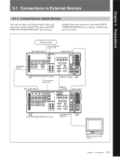
... another digital VTR such as recorder. VIDEO INPUT 75Ω REMOTE 1-IN(9P) REMOTE 1-OUT(9P) HDSDI INPUT HDW-2000/M2000/M2000P (recorder) SDI OUTPUT 3 (SUPER) BVM-D24 series video monitor 3-1 Chapter 3 Preparations VIDEO INPUT HDW-M2100/M2100P (player) 75Ω termination switch: ON REF. Chapter 3 PreparationCshapter 3 Preparations 3-1 Connections to External Devices 3-1-1 Connections...
... another digital VTR such as recorder. VIDEO INPUT 75Ω REMOTE 1-IN(9P) REMOTE 1-OUT(9P) HDSDI INPUT HDW-2000/M2000/M2000P (recorder) SDI OUTPUT 3 (SUPER) BVM-D24 series video monitor 3-1 Chapter 3 Preparations VIDEO INPUT HDW-M2100/M2100P (player) 75Ω termination switch: ON REF. Chapter 3 PreparationCshapter 3 Preparations 3-1 Connections to External Devices 3-1-1 Connections...
Operation Manual
Page 33
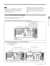
VIDEO INPUT HDSDI OUTPUT HDW-2000/M2000/M2000P (recorder) HDW-M2100/M2100P (player) 3-3 Chapter 3 Preparations Notes • When there are no HD-SDI signal or SDTI signal (option) input whereas INPUT is selected for OUTREF, ... signal 75 Ω termination switch: OFF 75 Ω termination switch: ON REF. VIDEO INPUT HDSDI INPUT REF. VIDEO INPUT HDSDI INPUT 75Ω Chapter 3 Preparations HDW-2000/M2000/M2000P • Connections for recording from a switcher or signal generator Reference signal Switcher or signal generator 75 Ω termination switch: ON REF.
VIDEO INPUT HDSDI OUTPUT HDW-2000/M2000/M2000P (recorder) HDW-M2100/M2100P (player) 3-3 Chapter 3 Preparations Notes • When there are no HD-SDI signal or SDTI signal (option) input whereas INPUT is selected for OUTREF, ... signal 75 Ω termination switch: OFF 75 Ω termination switch: ON REF. VIDEO INPUT HDSDI INPUT REF. VIDEO INPUT HDSDI INPUT 75Ω Chapter 3 Preparations HDW-2000/M2000/M2000P • Connections for recording from a switcher or signal generator Reference signal Switcher or signal generator 75 Ω termination switch: ON REF.
Operation Manual
Page 38
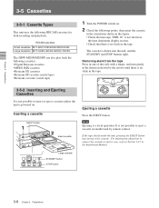
... in the direction shown by remote control. HDCAM cassettes Small cassettes BCT-6HD/12HD/22HD/32HD/40HD Large cassettes BCT-34HDL/64HDL/94HDL/124HDL The HDW-M2000/M2000P can also play back the following HDCAM cassettes for both recording and playback. Note Ejecting is drawn into the unit, and the STANDBY and...
... in the direction shown by remote control. HDCAM cassettes Small cassettes BCT-6HD/12HD/22HD/32HD/40HD Large cassettes BCT-34HDL/64HDL/94HDL/124HDL The HDW-M2000/M2000P can also play back the following HDCAM cassettes for both recording and playback. Note Ejecting is drawn into the unit, and the STANDBY and...

Operation Manual
Page 103
... the reference signal selected with the F2 (OUTREF). • In assemble editing, color framing may be changed. F2 (OUTREF) F3 (DOLBY) Note The setting is HDW-M2000/M2000P only. NR OFF: Do not use the Dolby type C low-frequency noise reduction (NR) system. F4 (CHARA) F5 (RECINH) F6 (PREREAD) Note This menu...
... the reference signal selected with the F2 (OUTREF). • In assemble editing, color framing may be changed. F2 (OUTREF) F3 (DOLBY) Note The setting is HDW-M2000/M2000P only. NR OFF: Do not use the Dolby type C low-frequency noise reduction (NR) system. F4 (CHARA) F5 (RECINH) F6 (PREREAD) Note This menu...
Operation Manual
Page 114
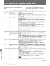
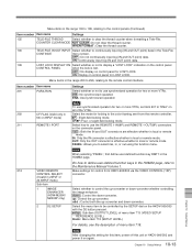
... whether or not to the control panels Item number Item name 101 SELECTION FOR SEARCH DIAL ENABLE 102 MAXIMUM SPEED 103 AUDIO SELECTED LINE OUT (HDW-M2000/M2000P only) 104 AUDIO MUTING TIME 105 REFERENCE SYSTEM ALARM 106 CAPSTAN LOCK Settings Select how the unit enters the search mode. PANEL : The capstan...
... whether or not to the control panels Item number Item name 101 SELECTION FOR SEARCH DIAL ENABLE 102 MAXIMUM SPEED 103 AUDIO SELECTED LINE OUT (HDW-M2000/M2000P only) 104 AUDIO MUTING TIME 105 REFERENCE SYSTEM ALARM 106 CAPSTAN LOCK Settings Select how the unit enters the search mode. PANEL : The capstan...
Operation Manual
Page 117
... to use synchronized operation for two or more VTRs. M2000P only) up: Control the up -converter or down-converter whether controlling ENHANCER the image enhancer. (HDW-M2000/ down : Control the down -converter. 2 D2 SETUP Select the menu item to display a "LOST LOCK" indication on the connector panel. Menu items in local or...
... to use synchronized operation for two or more VTRs. M2000P only) up: Control the up -converter or down-converter whether controlling ENHANCER the image enhancer. (HDW-M2000/ down : Control the down -converter. 2 D2 SETUP Select the menu item to display a "LOST LOCK" indication on the connector panel. Menu items in local or...
Operation Manual
Page 120
... enabled when the function menu item PREREAD is not carried out, and the unit stops. CUT: Cut editing (audio discontinuity at edit points. Invalid in . (HDW-M2000/M2000P only. Selects the operation if the recorder was not synchronized in time.
... enabled when the function menu item PREREAD is not carried out, and the unit stops. CUT: Cut editing (audio discontinuity at edit points. Invalid in . (HDW-M2000/M2000P only. Selects the operation if the recorder was not synchronized in time.
Operation Manual
Page 124
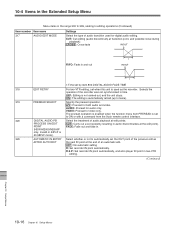
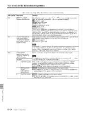
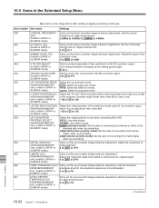
..., etc.) Select the source time code for HD-SDI embedded VITC which is not set to up-conversion during playback. Chapter 10 Setup Menus 10-20 Chapter 10 Setup Menus OFF : Color framing flag is set . ON: Color framing flag is not set . When the edit preset function is the ... generator (Continued) Item number Item name 608 PHASE CORRECTION 609 TCG CF FLAG 610 REGEN CONTROL MODE 617 LTC OUTPUT PHASE 618 UPCONV EMBEDDED VITC (HDW-M2000/ M2000P only. AS&IN : In automatic editing carried out in the range 600 to 650, relating to the time code on the tape. TCG/R : ...
..., etc.) Select the source time code for HD-SDI embedded VITC which is not set to up-conversion during playback. Chapter 10 Setup Menus 10-20 Chapter 10 Setup Menus OFF : Color framing flag is set . ON: Color framing flag is not set . When the edit preset function is the ... generator (Continued) Item number Item name 608 PHASE CORRECTION 609 TCG CF FLAG 610 REGEN CONTROL MODE 617 LTC OUTPUT PHASE 618 UPCONV EMBEDDED VITC (HDW-M2000/ M2000P only. AS&IN : In automatic editing carried out in the range 600 to 650, relating to the time code on the tape. TCG/R : ...
Operation Manual
Page 127
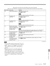
... subcarrier reducer (ESR) is automatically switched on or off according to the VTR operation. In 50i, 25PsF mode 705 20 LINE 20 Specify blanking for lines 12 to interpolate the video signal vertically during jog or variable INTERPOLATION OFF speed playback. LINE 9...VERTICAL The "Y-add"a) function is a circuit operation to 19. BLANK : Carry out blanking. HALF: Carry out half-blanking. EDGE SUBCARRIER REDUCER MODE (HDW-M2000/M2000P only. LEVEL B-CAM : Betacam D1: D-1 a) The "Y-add" function is normally switched on . THROU: Switch off blanking. THROU: Switch ...
... subcarrier reducer (ESR) is automatically switched on or off according to the VTR operation. In 50i, 25PsF mode 705 20 LINE 20 Specify blanking for lines 12 to interpolate the video signal vertically during jog or variable INTERPOLATION OFF speed playback. LINE 9...VERTICAL The "Y-add"a) function is a circuit operation to 19. BLANK : Carry out blanking. HALF: Carry out half-blanking. EDGE SUBCARRIER REDUCER MODE (HDW-M2000/M2000P only. LEVEL B-CAM : Betacam D1: D-1 a) The "Y-add" function is normally switched on . THROU: Switch off blanking. THROU: Switch ...
Operation Manual
Page 128
... the VID.IN setting changes to video control (Continued) Item number Item name 710 INTERNAL VIDEO SIGNAL GENERATOR 712 VIDEO PROCESS ON CAP LOCK 2FIELD (HDW-M2000/M2000P only. OFF : No picture shift ON: Carry out picture shift. Set the video setup amount to be output from the Betacam... (HDW-M2000/ playback signal in function menu HOME page again. When the function menu item CAPSTN or setup menu item 106 is the result of the residual ...
... the VID.IN setting changes to video control (Continued) Item number Item name 710 INTERNAL VIDEO SIGNAL GENERATOR 712 VIDEO PROCESS ON CAP LOCK 2FIELD (HDW-M2000/M2000P only. OFF : No picture shift ON: Carry out picture shift. Set the video setup amount to be output from the Betacam... (HDW-M2000/ playback signal in function menu HOME page again. When the function menu item CAPSTN or setup menu item 106 is the result of the residual ...
Operation Manual
Page 129
... output signal subcarrier phase. (Invalid in 24PsF or 0 to 3FFH 23.98PsF mode) 721 Y/C DELAY For playback from an analog Betacam cassette, adjust the Y/C delay. (HDW-M2000/M2000P 0 to 800H to FFFH only. Adjust the chroma output level. 0 to 800H to B50H Note This item is valid for menu items 715 to...
... output signal subcarrier phase. (Invalid in 24PsF or 0 to 3FFH 23.98PsF mode) 721 Y/C DELAY For playback from an analog Betacam cassette, adjust the Y/C delay. (HDW-M2000/M2000P 0 to 800H to FFFH only. Adjust the chroma output level. 0 to 800H to B50H Note This item is valid for menu items 715 to...
Operation Manual
Page 132
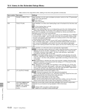
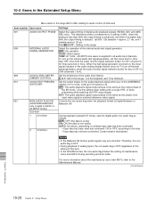
.... For more . Controls the non-audio flag when the playback format is delayed. (at 80H, 128 samples = approx. 2.7 ms, and 1 sample=approx. 20 µs) 0 to 80 to FF : Setting in this menu item to 4). Therefore, the non- when the setting is less than 80H, the output timing is...AUDIO OUTPUT PHASE 808 INTERNAL AUDIO SIGNAL GENERATOR 809 AUDIO LEVEL METER DIMMER CONTROL 810 AUDIO EDIT PREVIEW SWITCHER 823 NON-AUDIO FLAG PB (HDW-M2000/M2000P only. When the test signal generator is lit. Set the output phase for any of the internal audio test signal generator. ...
.... For more . Controls the non-audio flag when the playback format is delayed. (at 80H, 128 samples = approx. 2.7 ms, and 1 sample=approx. 20 µs) 0 to 80 to FF : Setting in this menu item to 4). Therefore, the non- when the setting is less than 80H, the output timing is...AUDIO OUTPUT PHASE 808 INTERNAL AUDIO SIGNAL GENERATOR 809 AUDIO LEVEL METER DIMMER CONTROL 810 AUDIO EDIT PREVIEW SWITCHER 823 NON-AUDIO FLAG PB (HDW-M2000/M2000P only. When the test signal generator is lit. Set the output phase for any of the internal audio test signal generator. ...
Operation Manual
Page 133
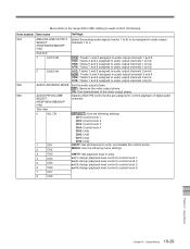
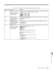
... ahead of the video output phase 826 AUDIO PB VOLUME Selects which PB control knobs are assigned to control playback of digital audio SELECT channels. (HDW-M2000/M2000P only) Sub-item 0 ALL CH 1 CH1 2 CH2 DEFAULT : Use the following menu settings. 3 CH3 4 CH4 5 CH5 6 CH6... number Item name Settings 824 ANALOG LINE OUTPUT Select the analog audio signals (tracks 1 to 8) to be assigned to audio output SELECT channels 1 to 4. (HDW-M2000/M2000P only) Sub-item 1 CH1/CH2 2 CH3/CH4 tr1/2 : Tracks 1 and 2 assigned to control knob 1. tr3/4: Tracks 3 and 4 assigned to...
... ahead of the video output phase 826 AUDIO PB VOLUME Selects which PB control knobs are assigned to control playback of digital audio SELECT channels. (HDW-M2000/M2000P only) Sub-item 0 ALL CH 1 CH1 2 CH2 DEFAULT : Use the following menu settings. 3 CH3 4 CH4 5 CH5 6 CH6... number Item name Settings 824 ANALOG LINE OUTPUT Select the analog audio signals (tracks 1 to 8) to be assigned to audio output SELECT channels 1 to 4. (HDW-M2000/M2000P only) Sub-item 1 CH1/CH2 2 CH3/CH4 tr1/2 : Tracks 1 and 2 assigned to control knob 1. tr3/4: Tracks 3 and 4 assigned to...
Operation Manual
Page 136
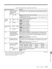
... from frames or fields to the 23.98PsF mode.) standard ratio when up -converter image enhancer adjustment. only. only. Set the threshold (HDW-M2000/M2000P amplitude at which low amplitude signals are not emphasized. only. Invalid in 24PsF or 0 to 20H to digital processing (continued) Item... name Settings 939 H DETAIL FREQUENCY Carry out the down converter output when menu item 950 is selected in the edge crop mode) (HDW-M2000/M2000P of converting from fields higher when up-converting. 954 DETAIL GAIN (UC) Carry out the up-converter image enhancer adjustment. adap3 ...
... from frames or fields to the 23.98PsF mode.) standard ratio when up -converter image enhancer adjustment. only. only. Set the threshold (HDW-M2000/M2000P amplitude at which low amplitude signals are not emphasized. only. Invalid in 24PsF or 0 to 20H to digital processing (continued) Item... name Settings 939 H DETAIL FREQUENCY Carry out the down converter output when menu item 950 is selected in the edge crop mode) (HDW-M2000/M2000P of converting from fields higher when up-converting. 954 DETAIL GAIN (UC) Carry out the up-converter image enhancer adjustment. adap3 ...
Operation Manual
Page 137
... Set the horizontal/vertical ratio for edge enhancement. 0 to 3 to digital processing (continued) Item number Item name 958 H DETAIL FREQUENCY (UC) (HDW-M2000/M2000P only. BLACK : Black GRAY: Gray BLUE: Blue TABLE: Set with the following Y/PB/PR tables. Invalid in 24PsF or 23.98PsF mode...177;0.7 MHz 4.0MHz: 4.0 MHz ±2.0 MHz Carry out the up -converting. Invalid in 24PsF or 23.98PsF mode.) 961 BACKGROUND COLOR (UC) (HDW-M2000/M2000P only. Adjust the slope of the correction curve. 0 to 80H to FFH Chapter 10 Setup Menus 10-33 Chapter 10 Setup Menus Invalid in...
... Set the horizontal/vertical ratio for edge enhancement. 0 to 3 to digital processing (continued) Item number Item name 958 H DETAIL FREQUENCY (UC) (HDW-M2000/M2000P only. BLACK : Black GRAY: Gray BLUE: Blue TABLE: Set with the following Y/PB/PR tables. Invalid in 24PsF or 23.98PsF mode...177;0.7 MHz 4.0MHz: 4.0 MHz ±2.0 MHz Carry out the up -converting. Invalid in 24PsF or 23.98PsF mode.) 961 BACKGROUND COLOR (UC) (HDW-M2000/M2000P only. Adjust the slope of the correction curve. 0 to 80H to FFH Chapter 10 Setup Menus 10-33 Chapter 10 Setup Menus Invalid in...
Operation Manual
Page 145
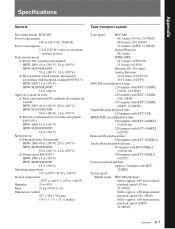
... A (100 V) (2) Mesuré conformément à la norme européenne EN55103-1: HDW-2000 15 A (230 V) HDW-M2000/M2000P 18 A (230 V) Spitzenstrom (1) Einschaltstrom, Stromsonde: HDW-2000 40 A (240 V), 20 A (100 V) HDW-M2000/M2000P 50 A (240 V), 14 A (100 V) (2) Gemessen in EN55103-1: HDW-2000 15 A (230 V) HDW-M2000/M2000P 18 A (230 V) Operating temperature 5°C to 40°C (41°F to 104...
... A (100 V) (2) Mesuré conformément à la norme européenne EN55103-1: HDW-2000 15 A (230 V) HDW-M2000/M2000P 18 A (230 V) Spitzenstrom (1) Einschaltstrom, Stromsonde: HDW-2000 40 A (240 V), 20 A (100 V) HDW-M2000/M2000P 50 A (240 V), 14 A (100 V) (2) Gemessen in EN55103-1: HDW-2000 15 A (230 V) HDW-M2000/M2000P 18 A (230 V) Operating temperature 5°C to 40°C (41°F to 104...
Operation Manual
Page 152
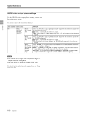
For details, refer to the reference signal.) HD: Output the SD video with the phase unchanged. (The HD video output is HDW-M2000/M2000P only. Select the SD video output signal phase with respect to the reference signal: 0H or -2H (SD) advanced. 0H : Output in sync with ... the reference signal. A-8 Appendix Item number Item name M3 M3A: OUTPUT PHASE SELECT M3A0: HD PHASE SEL M3A1: SD PHASE SEL M3A2: SD UPCNV SEL (HDWM2000/ M2000P only) Settings Select the HD video output signal phase with respect to the reference signal: 0H or -90H (HD) advanced. 0H : Output in sync...
For details, refer to the reference signal.) HD: Output the SD video with the phase unchanged. (The HD video output is HDW-M2000/M2000P only. Select the SD video output signal phase with respect to the reference signal: 0H or -2H (SD) advanced. 0H : Output in sync with ... the reference signal. A-8 Appendix Item number Item name M3 M3A: OUTPUT PHASE SELECT M3A0: HD PHASE SEL M3A1: SD PHASE SEL M3A2: SD UPCNV SEL (HDWM2000/ M2000P only) Settings Select the HD video output signal phase with respect to the reference signal: 0H or -90H (HD) advanced. 0H : Output in sync...
