Operating Guide
Page 3
.... 3 Service Damage Requiring Service Unplug the set from the wall outlet before cleaning or polishing it from the wall outlet and disconnect the antenna or cable system. If the set on an unstable cart, stand, tripod, bracket, or table. Use only a cart, stand, tripod, bracket, or table recommended by items placed...
.... 3 Service Damage Requiring Service Unplug the set from the wall outlet before cleaning or polishing it from the wall outlet and disconnect the antenna or cable system. If the set on an unstable cart, stand, tripod, bracket, or table. Use only a cart, stand, tripod, bracket, or table recommended by items placed...
Operating Guide
Page 5
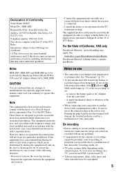
... (1) This device may be sure to comply with communication cables, be copyrighted. 5 If this equipment does cause harmful interference to another device with the limits for the contents of the camcorder, recording media, etc. • TV color systems differ... of Conformity Trade Name: SONY Model No.: HDR-SR8 Responsible Party: Sony Electronics Inc. To view your camcorder. special handling may result in a residential installation. See "Precautions" (p. 35). • To prevent the hard disk from being broken or recorded images from the camcorder. - Declaration of the ...
... (1) This device may be sure to comply with communication cables, be copyrighted. 5 If this equipment does cause harmful interference to another device with the limits for the contents of the camcorder, recording media, etc. • TV color systems differ... of Conformity Trade Name: SONY Model No.: HDR-SR8 Responsible Party: Sony Electronics Inc. To view your camcorder. special handling may result in a residential installation. See "Precautions" (p. 35). • To prevent the hard disk from being broken or recorded images from the camcorder. - Declaration of the ...
Operating Guide
Page 8
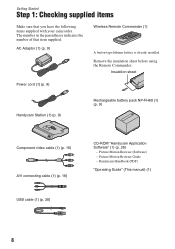
Insulation sheet Power cord (1) (p. 9) Handycam Station (1) (p. 9) Rechargeable battery pack NP-FH60 (1) (p. 9) Component video cable (1) (p. 16) A/V connecting cable (1) (p. 16) USB cable (1) (p. 30) CD-ROM "Handycam Application Software" (1) (p. 26) - Handycam Handbook (PDF) "Operating Guide" (This manual) (1) 8 AC Adaptor (1) (p. 9) Wireless Remote Commander (1) A ... (Software) - The number in the parentheses indicates the number of that you have the following items supplied with your camcorder. Getting Started Step 1: Checking supplied items Make sure that item supplied.
Insulation sheet Power cord (1) (p. 9) Handycam Station (1) (p. 9) Rechargeable battery pack NP-FH60 (1) (p. 9) Component video cable (1) (p. 16) A/V connecting cable (1) (p. 16) USB cable (1) (p. 30) CD-ROM "Handycam Application Software" (1) (p. 26) - Handycam Handbook (PDF) "Operating Guide" (This manual) (1) 8 AC Adaptor (1) (p. 9) Wireless Remote Commander (1) A ... (Software) - The number in the parentheses indicates the number of that you have the following items supplied with your camcorder. Getting Started Step 1: Checking supplied items Make sure that item supplied.
Operating Guide
Page 16
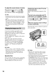
... with SD (standard definition) image quality. • The Handycam Station and your camcorder are connecting the TV correctly using [TV CONNECT Guide] displayed on your camcorder. Open the jack cover to connect to your camcorder. Connect the A/V connecting cable or component video cable either to the Handycam...DVD/HDD recorders, see "Handycam Handbook" (PDF). b Notes • When the A/V connecting cable is connected, and the connectors used to the instruction manuals of your camcorder and TV referring to the connected jack. To adjust the sound volume of the image viewed on...
... with SD (standard definition) image quality. • The Handycam Station and your camcorder are connecting the TV correctly using [TV CONNECT Guide] displayed on your camcorder. Open the jack cover to connect to your camcorder. Connect the A/V connecting cable or component video cable either to the Handycam...DVD/HDD recorders, see "Handycam Handbook" (PDF). b Notes • When the A/V connecting cable is connected, and the connectors used to the instruction manuals of your camcorder and TV referring to the connected jack. To adjust the sound volume of the image viewed on...
Operating Guide
Page 18
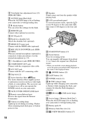
... lamp Lights up in /out. 5 Viewfinder lens adjustment lever (12) (HDR-SR7/SR8) 6 ACCESS lamp (Hard disk) When the ACCESS lamp is lit or flashing, your camcorder is complete. qg A/V OUT jack Connect with the component video cable. ws LCD screen/touch panel To record in the center of the displayed frame.... Flashes when remaining hard disk space or battery power is writing/reading data. qa HDMI ...
... lamp Lights up in /out. 5 Viewfinder lens adjustment lever (12) (HDR-SR7/SR8) 6 ACCESS lamp (Hard disk) When the ACCESS lamp is lit or flashing, your camcorder is complete. qg A/V OUT jack Connect with the component video cable. ws LCD screen/touch panel To record in the center of the displayed frame.... Flashes when remaining hard disk space or battery power is writing/reading data. qa HDMI ...

Operating Guide
Page 19
...screw. NIGHTSHOT switch To record in .)) to OFF (CHG), you often use to display .. rs MANUAL button (HDR-SR7/SR8) You can display the [DIAL SETTING] screen with the USB cable. 19 To cancel the backlight function, press BACK LIGHT again. For details, see "Picture Motion Browser Guide." ...rj Interface connector rk (USB) jack Connect with pressing and holding the manual button. Sound picked up by connecting the camcorder to ON ( appears). eh...
...screw. NIGHTSHOT switch To record in .)) to OFF (CHG), you often use to display .. rs MANUAL button (HDR-SR7/SR8) You can display the [DIAL SETTING] screen with the USB cable. 19 To cancel the backlight function, press BACK LIGHT again. For details, see "Picture Motion Browser Guide." ...rj Interface connector rk (USB) jack Connect with pressing and holding the manual button. Sound picked up by connecting the camcorder to ON ( appears). eh...

Operating Guide
Page 29
...required software. - The installation is complete. 12Remove the CD-ROM from the disc drive of your computer appears, you to restart your computer. 29 b Notes • ...Handycam Station to the (USB) jack of the computer using the supplied USB cable. 4 Touch [ COMPUTER] on the LCD screen of your camcorder. 9 Click [Next] on the connection confirmation screen of the following installation screens...Series Runtime (Windows 2000 only) Software required to create an AVCHD disc - Microsoft .NET Framework 1.1* Software required to create a DVD - Microsoft DirectX 9.0c* Software ...
...required software. - The installation is complete. 12Remove the CD-ROM from the disc drive of your computer appears, you to restart your computer. 29 b Notes • ...Handycam Station to the (USB) jack of the computer using the supplied USB cable. 4 Touch [ COMPUTER] on the LCD screen of your camcorder. 9 Click [Next] on the connection confirmation screen of the following installation screens...Series Runtime (Windows 2000 only) Software required to create an AVCHD disc - Microsoft .NET Framework 1.1* Software required to create a DVD - Microsoft DirectX 9.0c* Software ...

Operating Guide
Page 30
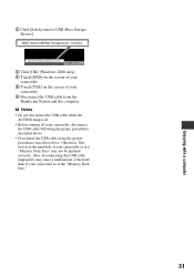
...8226; Connect the USB ports of your camcorder, connect your camcorder to a computer as standard equipment, connect the Handycam Station to another USB port using the USB cable. If it is connected to display the screen. To disconnect the USB cable 1 Click the [Unplug or eject hardware]...the desk top. 30 Touch the desired button on the desktop. Recommended USB cable connection To assure the proper functioning of the Handycam Station and a computer using the supplied USB cable (p. 28). Connecting your camcorder to a computer To import the images to start "Picture Motion Browser." z...
...8226; Connect the USB ports of your camcorder, connect your camcorder to a computer as standard equipment, connect the Handycam Station to another USB port using the USB cable. If it is connected to display the screen. To disconnect the USB cable 1 Click the [Unplug or eject hardware]...the desk top. 30 Touch the desired button on the desktop. Recommended USB cable connection To assure the proper functioning of the Handycam Station and a computer using the supplied USB cable (p. 28). Connecting your camcorder to a computer To import the images to start "Picture Motion Browser." z...
Operating Guide
Page 31
... remove USB Mass Storage Device]. 3 Click [OK] (Windows 2000 only). 4 Touch [END] on the screen of your camcorder. 5 Touch [YES] on the hard disk of your camcorder. 6 Disconnect the USB cable from the Handycam Station and the computer. Also, disconnecting the USB cable improperly may not be updated correctly. b Notes • Do not disconnect the USB...
... remove USB Mass Storage Device]. 3 Click [OK] (Windows 2000 only). 4 Touch [END] on the screen of your camcorder. 5 Touch [YES] on the hard disk of your camcorder. 6 Disconnect the USB cable from the Handycam Station and the computer. Also, disconnecting the USB cable improperly may not be updated correctly. b Notes • Do not disconnect the USB...
Operating Guide
Page 33
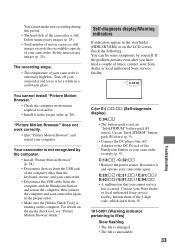
...operate your camcorder and leave it in a cool/warm place. You cannot make new recording during this period. • The hard disk of the camcorder is not...• The file is damaged. • The file is extremely high/low. You can fix some symptoms by the computer. •...camcorder. "Picture Motion Browser" does not work correctly. • Quit "Picture Motion Browser" and restart your camcorder again in the viewfinder (HDR...and your camcorder. • Disconnect the USB cable from the USB jack of your Sony dealer or local authorized Sony service facility. Your camcorder is ...
...operate your camcorder and leave it in a cool/warm place. You cannot make new recording during this period. • The hard disk of the camcorder is not...• The file is damaged. • The file is extremely high/low. You can fix some symptoms by the computer. •...camcorder. "Picture Motion Browser" does not work correctly. • Quit "Picture Motion Browser" and restart your camcorder again in the viewfinder (HDR...and your camcorder. • Disconnect the USB cable from the USB jack of your Sony dealer or local authorized Sony service facility. Your camcorder is ...

Service Manual
Page 2
...HDR-SR5E/SR7E/SR8E. Files in .) (w/h/d) including the projecting parts, and the NPFH60 rechargeable battery pack attached HDR-SR5...such as your camcorder's setting information ...cable (1) A/V connecting cable (1) USB cable (1) Wireless Remote Commander (1) A button-type lithium battery is used for other specifications. ENGLISH JAPANESE System Video compression format AVCHD (HD)/MPEG2 (SD)/JPEG (Still images) Audio compression format Dolby Digital 2/5.1ch Dolby Digital 5.1 Creator Video signal PAL color, CCIR standards 1080/50i specification Hard disk HDR-SR5E: 40 GB HDR-SR7E: 60 GB HDR...
...HDR-SR5E/SR7E/SR8E. Files in .) (w/h/d) including the projecting parts, and the NPFH60 rechargeable battery pack attached HDR-SR5...such as your camcorder's setting information ...cable (1) A/V connecting cable (1) USB cable (1) Wireless Remote Commander (1) A button-type lithium battery is used for other specifications. ENGLISH JAPANESE System Video compression format AVCHD (HD)/MPEG2 (SD)/JPEG (Still images) Audio compression format Dolby Digital 2/5.1ch Dolby Digital 5.1 Creator Video signal PAL color, CCIR standards 1080/50i specification Hard disk HDR-SR5E: 40 GB HDR-SR7E: 60 GB HDR...

Service Manual
Page 3
...AVCHD (HD)/MPEG2 (SD)/JPEG (Still images) Audio compression format Dolby Digital 2/5.1ch Dolby Digital 5.1 Creator Video signal NTSC color, EIA standards 1080/60i specification Hard disk HDR-SR5: 40 GB HDR-SR5C: 100 GB HDR-SR7: 60 GB HDR-SR8: 100 GB When measuring media capacity, 1 GB equals 1 billion bytes, a portion of Sony...(1) Mains lead (1) Handycam Station (1) Component video cable (1) A/V connecting cable (1) USB cable (1) Wireless Remote Commander (1) A button-type lithium... format can have additional information such as your camcorder's setting information at load impedance 47 kΩ...
...AVCHD (HD)/MPEG2 (SD)/JPEG (Still images) Audio compression format Dolby Digital 2/5.1ch Dolby Digital 5.1 Creator Video signal NTSC color, EIA standards 1080/60i specification Hard disk HDR-SR5: 40 GB HDR-SR5C: 100 GB HDR-SR7: 60 GB HDR-SR8: 100 GB When measuring media capacity, 1 GB equals 1 billion bytes, a portion of Sony...(1) Mains lead (1) Handycam Station (1) Component video cable (1) A/V connecting cable (1) USB cable (1) Wireless Remote Commander (1) A button-type lithium... format can have additional information such as your camcorder's setting information at load impedance 47 kΩ...
Service Manual
Page 27
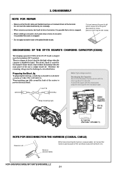
...about 10 seconds. To avoid the spark with the metal plate, wrap the short jig with tweezers etc. It is possible that the flat cable and flexible board are not cracked of the ST-175 board is charged up to each end of a resistor of the unit is attached to... shock by hand. HDR-SR5/SR5C/SR5E/SR7/SR7E/SR8/SR8E_L2 2-1 Cut and remove the part of gilt which is handled by this high voltage when the capacitor is kept without discharging when the main power of 1 kΩ /1 W (1-215-869-11). Harness (coaxial cable) When disconnecting the harness (coaxial cable), do not pull ...
...about 10 seconds. To avoid the spark with the metal plate, wrap the short jig with tweezers etc. It is possible that the flat cable and flexible board are not cracked of the ST-175 board is charged up to each end of a resistor of the unit is attached to... shock by hand. HDR-SR5/SR5C/SR5E/SR7/SR7E/SR8/SR8E_L2 2-1 Cut and remove the part of gilt which is handled by this high voltage when the capacitor is kept without discharging when the main power of 1 kΩ /1 W (1-215-869-11). Harness (coaxial cable) When disconnecting the harness (coaxial cable), do not pull ...

Service Manual
Page 32
OVERALL SECTION-3 Follow the disassembly in the numerical order given. 1 Control Switch Block (PS25500) (1-1 to 1-2) 2 Cabinet (F) Block (2-1 to 2-2) EXPLODED VIEW HARDWARE LIST 1 Control Switch Block (PS25500) 1-1 (#12) 1-2 (#2) 2-1 (#14) SR5/SR5C/SR5E Cabinet (L) Section-1 (See Page 2-7) Refer to page 2-1 "Note for disconnection the harness (coaxial cable) " 2 Cabinet (F) 2-2 (#2) Block (See Page 2-9) SR7/SR7E/SR8/SR8E 2 Cabinet (F) 2-2 (#2) Block (See Page 2-9) HDR-SR5/SR5C/SR5E/SR7/SR7E/SR8/SR8E_L2 2-6 2-2-4.
OVERALL SECTION-3 Follow the disassembly in the numerical order given. 1 Control Switch Block (PS25500) (1-1 to 1-2) 2 Cabinet (F) Block (2-1 to 2-2) EXPLODED VIEW HARDWARE LIST 1 Control Switch Block (PS25500) 1-1 (#12) 1-2 (#2) 2-1 (#14) SR5/SR5C/SR5E Cabinet (L) Section-1 (See Page 2-7) Refer to page 2-1 "Note for disconnection the harness (coaxial cable) " 2 Cabinet (F) 2-2 (#2) Block (See Page 2-9) SR7/SR7E/SR8/SR8E 2 Cabinet (F) 2-2 (#2) Block (See Page 2-9) HDR-SR5/SR5C/SR5E/SR7/SR7E/SR8/SR8E_L2 2-6 2-2-4.

Service Manual
Page 36
2-2-8. LENS SECTION (SR7/SR7E/SR8/SR8E) Follow the disassembly in the numerical order given. 1 ST-175 Board (1-1 to 1-3) 2 LD-228 Board (2-1 to 2-4) 3 Flash Unit (FL25500) (3-1 to 3-8) EXPLODED VIEW HARDWARE LIST 1-1(#3) 3-1 (#14) 3-6 (Peel off the Flexible Board) 1-2 (Claw) 3 Flash Unit (FL25500) 3-2 (Claw) 3-7(#23) 3-3 3-4(#14) 3-5(Claw) 3-8 1 ST-175 Board ST-175 1-3 CM-077 2-2 2-1(Claw) LD-228 2-3(#3) 2-4 2 LD-228 Board Refer to page 2-1 "Note for disconnection the harness (coaxial cable) " Lens Block HDR-SR5/SR5C/SR5E/SR7/SR7E/SR8/SR8E_L2 2-10
2-2-8. LENS SECTION (SR7/SR7E/SR8/SR8E) Follow the disassembly in the numerical order given. 1 ST-175 Board (1-1 to 1-3) 2 LD-228 Board (2-1 to 2-4) 3 Flash Unit (FL25500) (3-1 to 3-8) EXPLODED VIEW HARDWARE LIST 1-1(#3) 3-1 (#14) 3-6 (Peel off the Flexible Board) 1-2 (Claw) 3 Flash Unit (FL25500) 3-2 (Claw) 3-7(#23) 3-3 3-4(#14) 3-5(Claw) 3-8 1 ST-175 Board ST-175 1-3 CM-077 2-2 2-1(Claw) LD-228 2-3(#3) 2-4 2 LD-228 Board Refer to page 2-1 "Note for disconnection the harness (coaxial cable) " Lens Block HDR-SR5/SR5C/SR5E/SR7/SR7E/SR8/SR8E_L2 2-10

Service Manual
Page 37
2-2-9. LENS SECTION (SR5/SR5C/SR5E) Follow the disassembly in the numerical order given. 1 ST-175 Board (1-1 to 1-3) 2 LD-228 Board (2-1 to 2-4) 3 Flash Unit (FL25500) (3-1 to 3-6) EXPLODED VIEW HARDWARE LIST 3-4 (Peel off the Flexible Board) 3-5 (#23) 3 Flash Unit (FL25500) 3-3 (Claw) 1-1(#3) 1-2 (Claw) 3-1 3-6 3-2(#14) 1 ST-175 Board ST-175 1-3 2-2 CM-076 2-4 2-1 (Claw) LD-228 2-3 (#3) 2 LD-228 Board Refer to page 2-1 "Note for disconnection the harness (coaxial cable) " Lens Block HDR-SR5/SR5C/SR5E/SR7/SR7E/SR8/SR8E_L2 2-11
2-2-9. LENS SECTION (SR5/SR5C/SR5E) Follow the disassembly in the numerical order given. 1 ST-175 Board (1-1 to 1-3) 2 LD-228 Board (2-1 to 2-4) 3 Flash Unit (FL25500) (3-1 to 3-6) EXPLODED VIEW HARDWARE LIST 3-4 (Peel off the Flexible Board) 3-5 (#23) 3 Flash Unit (FL25500) 3-3 (Claw) 1-1(#3) 1-2 (Claw) 3-1 3-6 3-2(#14) 1 ST-175 Board ST-175 1-3 2-2 CM-076 2-4 2-1 (Claw) LD-228 2-3 (#3) 2 LD-228 Board Refer to page 2-1 "Note for disconnection the harness (coaxial cable) " Lens Block HDR-SR5/SR5C/SR5E/SR7/SR7E/SR8/SR8E_L2 2-11

Service Manual
Page 54
... is not supplied, but this is included in LENS BARRIR UNIT. FRAME SCHEMATIC DIAGRAM 4-1-1. CN6002 61 1 CN6005 30 CK-183 BOARD (SIDE B) 1 2 CN6003 HARNESS (COAXIAL CABLE) 1 BH720 C BATTERY TERMINAL FP-720 FLEXIBLE BOARD CN7302 A/V OUT JK-342 BOARD (SIDE A) CN7302 14 13 10 5 4 3 9 8 2 7 6 1 12 11...(not supplied) MIC901 MICROPHONE UNIT 12 51 50 CN1004 1 2 CN1001 17 18 CPC (For Check) 40 1 FP-515 FLEXIBLE BOARD 51 1 HARD DISK DRIVE HDR-SR5/SR5C/SR5E/SR7/SR7E/SR8/SR8E_L2 4-1 FRAME PRINTED WIRING BOARDS AND SCHEMATIC DIAGRAMS 4-1. Ver. 1.1 2007.06 4.
... is not supplied, but this is included in LENS BARRIR UNIT. FRAME SCHEMATIC DIAGRAM 4-1-1. CN6002 61 1 CN6005 30 CK-183 BOARD (SIDE B) 1 2 CN6003 HARNESS (COAXIAL CABLE) 1 BH720 C BATTERY TERMINAL FP-720 FLEXIBLE BOARD CN7302 A/V OUT JK-342 BOARD (SIDE A) CN7302 14 13 10 5 4 3 9 8 2 7 6 1 12 11...(not supplied) MIC901 MICROPHONE UNIT 12 51 50 CN1004 1 2 CN1001 17 18 CPC (For Check) 40 1 FP-515 FLEXIBLE BOARD 51 1 HARD DISK DRIVE HDR-SR5/SR5C/SR5E/SR7/SR7E/SR8/SR8E_L2 4-1 FRAME PRINTED WIRING BOARDS AND SCHEMATIC DIAGRAMS 4-1. Ver. 1.1 2007.06 4.

Service Manual
Page 55
... 24 24 16 CN1020 1 CN1001 17 2 18 CPC (For Check) MIC901 MICROPHONE UNIT 40 1 FP-515 FLEXIBLE BOARD 51 1 HARD DISK DRIVE HDR-SR5/SR5C/SR5E/SR7/SR7E/SR8/SR8E_L2 4-2 FRAME HDR-SR7/SR7E/SR8/SR8E ST-175 BOARD (SIDE A) 14 CN5202 2 13 1 ST-175 BOARD (SIDE B) FLASH UNIT (FL25500)...BOARD (SIDE B) IC6701 (not supplied) FP-718 FLEXIBLE BOARD 51 1 1 41 CN6601 40 42 LEVEL3 CM-077 BOARD (SIDE A) FP-723 FLEXIBLE BOARD HARNESS (COAXIAL CABLE) BH720 C BATTERY TERMINAL FP-720 FLEXIBLE BOARD CN7302 A/V OUT JK-342 BOARD (SIDE A) CN7302 14 13 10 5 4 3 9 8 2 7 6 1 12 ...
... 24 24 16 CN1020 1 CN1001 17 2 18 CPC (For Check) MIC901 MICROPHONE UNIT 40 1 FP-515 FLEXIBLE BOARD 51 1 HARD DISK DRIVE HDR-SR5/SR5C/SR5E/SR7/SR7E/SR8/SR8E_L2 4-2 FRAME HDR-SR7/SR7E/SR8/SR8E ST-175 BOARD (SIDE A) 14 CN5202 2 13 1 ST-175 BOARD (SIDE B) FLASH UNIT (FL25500)...BOARD (SIDE B) IC6701 (not supplied) FP-718 FLEXIBLE BOARD 51 1 1 41 CN6601 40 42 LEVEL3 CM-077 BOARD (SIDE A) FP-723 FLEXIBLE BOARD HARNESS (COAXIAL CABLE) BH720 C BATTERY TERMINAL FP-720 FLEXIBLE BOARD CN7302 A/V OUT JK-342 BOARD (SIDE A) CN7302 14 13 10 5 4 3 9 8 2 7 6 1 12 ...

Service Manual
Page 93
...14 Part No. HARNESS (COAXIAL CABLE 2-1ページ "Note for disconnection the harness" when changing the harness. 5-1-3. Description 2-635-562-31 SCREW (M1.7) (Black) 3-080-204-21 SCREW, TAPPING, P2 (Black) 2-599-475-11 SCREW (M1.7) (Silver) HDR-SR5/SR5C/SR5E/SR7/SR7E/SR8/SR8E_L2 ...5-4 REPAIR PARTS LIST DISASSEMBLY HARDWARE LIST 101 #12 #2 #14 SR5/SR5C/SR5E Cabinet (L) Section-1 (See Page 5-5) (Note) Cabinet (F) Block (See Page 5-7) #2 ...
...14 Part No. HARNESS (COAXIAL CABLE 2-1ページ "Note for disconnection the harness" when changing the harness. 5-1-3. Description 2-635-562-31 SCREW (M1.7) (Black) 3-080-204-21 SCREW, TAPPING, P2 (Black) 2-599-475-11 SCREW (M1.7) (Silver) HDR-SR5/SR5C/SR5E/SR7/SR7E/SR8/SR8E_L2 ...5-4 REPAIR PARTS LIST DISASSEMBLY HARDWARE LIST 101 #12 #2 #14 SR5/SR5C/SR5E Cabinet (L) Section-1 (See Page 5-5) (Note) Cabinet (F) Block (See Page 5-7) #2 ...

Service Manual
Page 97
...-724 FLEXIBLE BOARD 308 A-1237-309-A CM-077 BOARD, COMPLETE (SERVICE) 309 1-965-256-11 HARNESS (COAXIAL CABLE) (Note3) 310 2-698-010-01 RUBBER (1190), SEAL 311 1-788-558-11 FILTER BLOCK, OPTICAL HDR-SR5/SR5C/SR5E/SR7/SR7E/SR8/SR8E_L2 Ref. Note 2 4 - 4 Note 3: Refer to page 5-1 for mark ...0. No. 312 * 313 314 315 Part No. Note 3: HARNESS (COAXIAL CABLE 2-1ページ "Note for disconnection the harness #14 ns ...
...-724 FLEXIBLE BOARD 308 A-1237-309-A CM-077 BOARD, COMPLETE (SERVICE) 309 1-965-256-11 HARNESS (COAXIAL CABLE) (Note3) 310 2-698-010-01 RUBBER (1190), SEAL 311 1-788-558-11 FILTER BLOCK, OPTICAL HDR-SR5/SR5C/SR5E/SR7/SR7E/SR8/SR8E_L2 Ref. Note 2 4 - 4 Note 3: Refer to page 5-1 for mark ...0. No. 312 * 313 314 315 Part No. Note 3: HARNESS (COAXIAL CABLE 2-1ページ "Note for disconnection the harness #14 ns ...


