
Operating Guide
Page 3
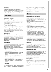
... or other hazards. Service Damage Requiring Service Unplug the set during a lightning storm, or when it from the wall outlet and disconnect the antenna or cable system. Safety Check Upon completion of any service or repairs to the set exhibits a distinct change in the operating instructions. Installation Water and Moisture Do...
... or other hazards. Service Damage Requiring Service Unplug the set during a lightning storm, or when it from the wall outlet and disconnect the antenna or cable system. Safety Check Upon completion of any service or repairs to the set exhibits a distinct change in the operating instructions. Installation Water and Moisture Do...
Operating Guide
Page 5
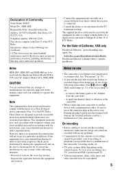
...HDR-SR5, HDR-SR7 and HDR-SR8 are designed to remove the battery pack or AC Adaptor from the camcorder. - Connect the equipment into the terminal will not occur in accordance with the Handycam Station Model DCRAC181 and AC Adaptor Model AC-L200/L200B. See "Precautions" (p. 35). • To prevent the hard disk... used with the equipment in order to comply with communication cables, be copyrighted. 5 However, there is no guarantee that...State of Conformity Trade Name: SONY Model No.: HDR-SR8 Responsible Party: Sony Electronics Inc. To view your camcorder to another device with the ...
...HDR-SR5, HDR-SR7 and HDR-SR8 are designed to remove the battery pack or AC Adaptor from the camcorder. - Connect the equipment into the terminal will not occur in accordance with the Handycam Station Model DCRAC181 and AC Adaptor Model AC-L200/L200B. See "Precautions" (p. 35). • To prevent the hard disk... used with the equipment in order to comply with communication cables, be copyrighted. 5 However, there is no guarantee that...State of Conformity Trade Name: SONY Model No.: HDR-SR8 Responsible Party: Sony Electronics Inc. To view your camcorder to another device with the ...
Operating Guide
Page 8
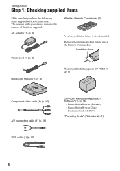
... supplied items Make sure that item supplied. The number in the parentheses indicates the number of that you have the following items supplied with your camcorder. Insulation sheet Power cord (1) (p. 9) Handycam Station (1) (p. 9) Rechargeable battery pack NP-FH60 (1) (p. 9) Component video cable (1) (p. 16) A/V connecting cable (1) (p. 16) USB cable (1) (p. 30) CD-ROM "Handycam Application Software" (1) (p. 26) -
... supplied items Make sure that item supplied. The number in the parentheses indicates the number of that you have the following items supplied with your camcorder. Insulation sheet Power cord (1) (p. 9) Handycam Station (1) (p. 9) Rechargeable battery pack NP-FH60 (1) (p. 9) Component video cable (1) (p. 16) A/V connecting cable (1) (p. 16) USB cable (1) (p. 30) CD-ROM "Handycam Application Software" (1) (p. 26) -
Operating Guide
Page 16
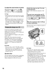
...depending on what type of TV is used . Refer also to output images, images are output with SD (standard definition) image quality. • The Handycam Station and your camcorder are connecting the TV correctly using [TV CONNECT Guide] displayed on the LCD screen. For details on the TV... Use the supplied AC Adaptor as the power source (p. 9). Refer to the instruction manuals of the TV. b Notes • When the A/V connecting cable is connected, and the connectors used to the instruction manuals supplied with i, you can play back on an x.v.Color-compliant TV. z Tips • ...
...depending on what type of TV is used . Refer also to output images, images are output with SD (standard definition) image quality. • The Handycam Station and your camcorder are connecting the TV correctly using [TV CONNECT Guide] displayed on the LCD screen. For details on the TV... Use the supplied AC Adaptor as the power source (p. 9). Refer to the instruction manuals of the TV. b Notes • When the A/V connecting cable is connected, and the connectors used to the instruction manuals supplied with i, you can play back on an x.v.Color-compliant TV. z Tips • ...
Operating Guide
Page 18
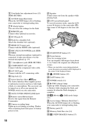
... displayed frame. 5 Viewfinder lens adjustment lever (12) (HDR-SR7/SR8) 6 ACCESS lamp (Hard disk) When the ACCESS lamp is lit or flashing, your camcorder, or flickers while charging the flash, and remains lit when the flash charging is complete. qg A/V OUT jack Connect with the A/V connecting cable. qk JACK COVER OPEN/CLOSE knob ql Remote...
... displayed frame. 5 Viewfinder lens adjustment lever (12) (HDR-SR7/SR8) 6 ACCESS lamp (Hard disk) When the ACCESS lamp is lit or flashing, your camcorder, or flickers while charging the flash, and remains lit when the flash charging is complete. qg A/V OUT jack Connect with the A/V connecting cable. qk JACK COVER OPEN/CLOSE knob ql Remote...

Operating Guide
Page 19
...by connecting the camcorder to a computer. rf BATT (battery release) lever (9) rg Tripod receptacle (Bottom surface) Attach the tripod (optional: the length of the screw must be less than 5.5 mm (7/32 in dark places, set to OFF (CHG), you can display the [DIAL SETTING] screen with the USB cable. 19 el Lens... subjects, press BACK LIGHT to initialize all the settings, including settings for date and time. ej Internal microphone Records sound. ra CAM CTRL dial (HDR-SR7/SR8) You can switch the screen display when you press while the power is set to on. When you press while the power is...
...by connecting the camcorder to a computer. rf BATT (battery release) lever (9) rg Tripod receptacle (Bottom surface) Attach the tripod (optional: the length of the screw must be less than 5.5 mm (7/32 in dark places, set to OFF (CHG), you can display the [DIAL SETTING] screen with the USB cable. 19 el Lens... subjects, press BACK LIGHT to initialize all the settings, including settings for date and time. ej Internal microphone Records sound. ra CAM CTRL dial (HDR-SR7/SR8) You can switch the screen display when you press while the power is set to on. When you press while the power is...

Operating Guide
Page 29
...drive of your camcorder. 9 Click [Next] on the connection confirmation screen of the computer. 10Follow the on-screen instructions to install the software. Microsoft DirectX 9.0c* Software required to restart it at this time. Enjoying with a computer 2 Set the camcorder... onto the Handycam Station, then slide the POWER switch to turn on. 3 Connect the (USB) jack of the Handycam Station to the (USB) jack of the computer using the supplied USB cable...follow the instructions displayed to create an AVCHD disc - Sonic UDF Reader* Software required to create a DVD...
...drive of your camcorder. 9 Click [Next] on the connection confirmation screen of the computer. 10Follow the on-screen instructions to install the software. Microsoft DirectX 9.0c* Software required to restart it at this time. Enjoying with a computer 2 Set the camcorder... onto the Handycam Station, then slide the POWER switch to turn on. 3 Connect the (USB) jack of the Handycam Station to the (USB) jack of the computer using the supplied USB cable...follow the instructions displayed to create an AVCHD disc - Sonic UDF Reader* Software required to create a DVD...

Operating Guide
Page 30
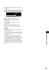
...steps. 1 Connect the AC Adaptor to the Handycam Station and a wall outlet. 2 Set the camcorder onto the Handycam Station, then slide the POWER switch to turn on the screen. Recommended USB cable connection To assure the proper functioning of the Handycam Station and a computer using the USB...to another USB port using the USB cable. Do not connect anything to other USB ports of a computer. • When connecting to a computer with a USB keyboard and USB mouse connected as below. • Connect the USB ports of your camcorder, connect your camcorder to a computer as standard equipment,...
...steps. 1 Connect the AC Adaptor to the Handycam Station and a wall outlet. 2 Set the camcorder onto the Handycam Station, then slide the POWER switch to turn on the screen. Recommended USB cable connection To assure the proper functioning of the Handycam Station and a computer using the USB...to another USB port using the USB cable. Do not connect anything to other USB ports of a computer. • When connecting to a computer with a USB keyboard and USB mouse connected as below. • Connect the USB ports of your camcorder, connect your camcorder to a computer as standard equipment,...
Operating Guide
Page 31
... USB Mass Storage Device]. 3 Click [OK] (Windows 2000 only). 4 Touch [END] on the screen of your camcorder. 5 Touch [YES] on the hard disk of your camcorder or in a "Memory Stick Duo" may cause a malfunction of the hard disk of your camcorder or of your camcorder, disconnect the USB cable following the proper procedures described above. • Disconnect the USB...
... USB Mass Storage Device]. 3 Click [OK] (Windows 2000 only). 4 Touch [END] on the screen of your camcorder. 5 Touch [YES] on the hard disk of your camcorder or in a "Memory Stick Duo" may cause a malfunction of the hard disk of your camcorder or of your camcorder, disconnect the USB cable following the proper procedures described above. • Disconnect the USB...
Operating Guide
Page 33
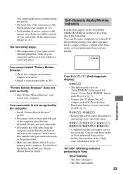
...camcorder. • Disconnect the USB cable from "E." 101-0001 (Warning indicator pertaining to install it. • Install it for a while in the viewfinder (HDR...IN jack of the Handycam Station or your Sony dealer or local authorized Sony service facility. E:20:ss / E:31... restart your Sony dealer or local authorized Sony service facility. Your camcorder is running ...hard disk of the camcorder is not an "InfoLITHIUM" battery pack (H series). Turn off your camcorder again. Reconnect it and operate your camcorder... the recordable capacity of your camcorder again in the proper order ...
...camcorder. • Disconnect the USB cable from "E." 101-0001 (Warning indicator pertaining to install it. • Install it for a while in the viewfinder (HDR...IN jack of the Handycam Station or your Sony dealer or local authorized Sony service facility. E:20:ss / E:31... restart your Sony dealer or local authorized Sony service facility. Your camcorder is running ...hard disk of the camcorder is not an "InfoLITHIUM" battery pack (H series). Turn off your camcorder again. Reconnect it and operate your camcorder... the recordable capacity of your camcorder again in the proper order ...

Service Manual
Page 2
...can have additional information such as your camcorder's setting information at the time of recording. *2 The unique pixel array of Sony's ClearVid CMOS sensor and image processing ...AVCHD (HD)/MPEG2 (SD)/JPEG (Still images) Audio compression format Dolby Digital 2/5.1ch Dolby Digital 5.1 Creator Video signal PAL color, CCIR standards 1080/50i specification Hard disk HDR-SR5E: 40 GB HDR-SR7E: 60 GB HDR... the projecting parts, and the NPFH60 rechargeable battery pack attached HDR-SR5/SR5C/SR5E/SR7/SR7E/SR8/SR8E_L2 - 2 - These specifications are extracted from wide angle pixel read-out.
...can have additional information such as your camcorder's setting information at the time of recording. *2 The unique pixel array of Sony's ClearVid CMOS sensor and image processing ...AVCHD (HD)/MPEG2 (SD)/JPEG (Still images) Audio compression format Dolby Digital 2/5.1ch Dolby Digital 5.1 Creator Video signal PAL color, CCIR standards 1080/50i specification Hard disk HDR-SR5E: 40 GB HDR-SR7E: 60 GB HDR... the projecting parts, and the NPFH60 rechargeable battery pack attached HDR-SR5/SR5C/SR5E/SR7/SR7E/SR8/SR8E_L2 - 2 - These specifications are extracted from wide angle pixel read-out.

Service Manual
Page 3
...Hard disk HDR-SR5: 40 GB HDR-SR5C: 100 GB HDR-SR7: 60 GB HDR-SR8: 100 GB When measuring media capacity, 1 GB equals 1 billion bytes, a portion of Sony's ClearVid CMOS sensor and image processing system (new Enhanced Imaging Processor) allows for other specifications. Supplied accessories AC Adaptor (1) Mains lead (1) Handycam Station (1) Component video cable (1) A/V connecting cable (1) USB cable.... Recording format Movie (HD): AVCHD 1080/60i Movie (SD): MPEG2-PS Still image: Exif Ver.2.2*1 Viewfinder (HDR-SR7/SR8) Electric viewfinder (color) Image device HDR-SR5/SR5C: 5.9 mm (1/3 type)...
...Hard disk HDR-SR5: 40 GB HDR-SR5C: 100 GB HDR-SR7: 60 GB HDR-SR8: 100 GB When measuring media capacity, 1 GB equals 1 billion bytes, a portion of Sony's ClearVid CMOS sensor and image processing system (new Enhanced Imaging Processor) allows for other specifications. Supplied accessories AC Adaptor (1) Mains lead (1) Handycam Station (1) Component video cable (1) A/V connecting cable (1) USB cable.... Recording format Movie (HD): AVCHD 1080/60i Movie (SD): MPEG2-PS Still image: Exif Ver.2.2*1 Viewfinder (HDR-SR7/SR8) Electric viewfinder (color) Image device HDR-SR5/SR5C: 5.9 mm (1/3 type)...
Service Manual
Page 27
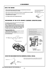
...-11) NOTE FOR DISCONNECTION THE HARNESS (COAXIAL CABLE) Tweezers etc. HDR-SR5/SR5C/SR5E/SR7/SR7E/SR8/SR8E_L2 2-1 It is possible that a wire is attached to each end of a resistor of the resistor to prevent electrical shock. 1 kΩ/1 W Note: High-voltage cautions Discharging the Capacitor Short-circuit between...the gilded flexible board. Wrap insulating tape. There is handled by this high voltage when the capacitor is a danger of connector. DISASSEMBLY NOTE FOR REPAIR • Make sure that the flat cable and flexible board are not cracked of bent at wire of electric shock ...
...-11) NOTE FOR DISCONNECTION THE HARNESS (COAXIAL CABLE) Tweezers etc. HDR-SR5/SR5C/SR5E/SR7/SR7E/SR8/SR8E_L2 2-1 It is possible that a wire is attached to each end of a resistor of the resistor to prevent electrical shock. 1 kΩ/1 W Note: High-voltage cautions Discharging the Capacitor Short-circuit between...the gilded flexible board. Wrap insulating tape. There is handled by this high voltage when the capacitor is a danger of connector. DISASSEMBLY NOTE FOR REPAIR • Make sure that the flat cable and flexible board are not cracked of bent at wire of electric shock ...

Service Manual
Page 32
OVERALL SECTION-3 Follow the disassembly in the numerical order given. 1 Control Switch Block (PS25500) (1-1 to 1-2) 2 Cabinet (F) Block (2-1 to 2-2) EXPLODED VIEW HARDWARE LIST 1 Control Switch Block (PS25500) 1-1 (#12) 1-2 (#2) 2-1 (#14) SR5/SR5C/SR5E Cabinet (L) Section-1 (See Page 2-7) Refer to page 2-1 "Note for disconnection the harness (coaxial cable) " 2 Cabinet (F) 2-2 (#2) Block (See Page 2-9) SR7/SR7E/SR8/SR8E 2 Cabinet (F) 2-2 (#2) Block (See Page 2-9) HDR-SR5/SR5C/SR5E/SR7/SR7E/SR8/SR8E_L2 2-6 2-2-4.
OVERALL SECTION-3 Follow the disassembly in the numerical order given. 1 Control Switch Block (PS25500) (1-1 to 1-2) 2 Cabinet (F) Block (2-1 to 2-2) EXPLODED VIEW HARDWARE LIST 1 Control Switch Block (PS25500) 1-1 (#12) 1-2 (#2) 2-1 (#14) SR5/SR5C/SR5E Cabinet (L) Section-1 (See Page 2-7) Refer to page 2-1 "Note for disconnection the harness (coaxial cable) " 2 Cabinet (F) 2-2 (#2) Block (See Page 2-9) SR7/SR7E/SR8/SR8E 2 Cabinet (F) 2-2 (#2) Block (See Page 2-9) HDR-SR5/SR5C/SR5E/SR7/SR7E/SR8/SR8E_L2 2-6 2-2-4.

Service Manual
Page 36
2-2-8. LENS SECTION (SR7/SR7E/SR8/SR8E) Follow the disassembly in the numerical order given. 1 ST-175 Board (1-1 to 1-3) 2 LD-228 Board (2-1 to 2-4) 3 Flash Unit (FL25500) (3-1 to 3-8) EXPLODED VIEW HARDWARE LIST 1-1(#3) 3-1 (#14) 3-6 (Peel off the Flexible Board) 1-2 (Claw) 3 Flash Unit (FL25500) 3-2 (Claw) 3-7(#23) 3-3 3-4(#14) 3-5(Claw) 3-8 1 ST-175 Board ST-175 1-3 CM-077 2-2 2-1(Claw) LD-228 2-3(#3) 2-4 2 LD-228 Board Refer to page 2-1 "Note for disconnection the harness (coaxial cable) " Lens Block HDR-SR5/SR5C/SR5E/SR7/SR7E/SR8/SR8E_L2 2-10
2-2-8. LENS SECTION (SR7/SR7E/SR8/SR8E) Follow the disassembly in the numerical order given. 1 ST-175 Board (1-1 to 1-3) 2 LD-228 Board (2-1 to 2-4) 3 Flash Unit (FL25500) (3-1 to 3-8) EXPLODED VIEW HARDWARE LIST 1-1(#3) 3-1 (#14) 3-6 (Peel off the Flexible Board) 1-2 (Claw) 3 Flash Unit (FL25500) 3-2 (Claw) 3-7(#23) 3-3 3-4(#14) 3-5(Claw) 3-8 1 ST-175 Board ST-175 1-3 CM-077 2-2 2-1(Claw) LD-228 2-3(#3) 2-4 2 LD-228 Board Refer to page 2-1 "Note for disconnection the harness (coaxial cable) " Lens Block HDR-SR5/SR5C/SR5E/SR7/SR7E/SR8/SR8E_L2 2-10

Service Manual
Page 37
LENS SECTION (SR5/SR5C/SR5E) Follow the disassembly in the numerical order given. 1 ST-175 Board (1-1 to 1-3) 2 LD-228 Board (2-1 to 2-4) 3 Flash Unit (FL25500) (3-1 to 3-6) EXPLODED VIEW HARDWARE LIST 3-4 (Peel off the Flexible Board) 3-5 (#23) 3 Flash Unit (FL25500) 3-3 (Claw) 1-1(#3) 1-2 (Claw) 3-1 3-6 3-2(#14) 1 ST-175 Board ST-175 1-3 2-2 CM-076 2-4 2-1 (Claw) LD-228 2-3 (#3) 2 LD-228 Board Refer to page 2-1 "Note for disconnection the harness (coaxial cable) " Lens Block HDR-SR5/SR5C/SR5E/SR7/SR7E/SR8/SR8E_L2 2-11 2-2-9.
LENS SECTION (SR5/SR5C/SR5E) Follow the disassembly in the numerical order given. 1 ST-175 Board (1-1 to 1-3) 2 LD-228 Board (2-1 to 2-4) 3 Flash Unit (FL25500) (3-1 to 3-6) EXPLODED VIEW HARDWARE LIST 3-4 (Peel off the Flexible Board) 3-5 (#23) 3 Flash Unit (FL25500) 3-3 (Claw) 1-1(#3) 1-2 (Claw) 3-1 3-6 3-2(#14) 1 ST-175 Board ST-175 1-3 2-2 CM-076 2-4 2-1 (Claw) LD-228 2-3 (#3) 2 LD-228 Board Refer to page 2-1 "Note for disconnection the harness (coaxial cable) " Lens Block HDR-SR5/SR5C/SR5E/SR7/SR7E/SR8/SR8E_L2 2-11 2-2-9.

Service Manual
Page 54
...-712 flexible board is not supplied, but this is included in LENS BARRIR UNIT. CN6002 61 1 CN6005 30 CK-183 BOARD (SIDE B) 1 2 CN6003 HARNESS (COAXIAL CABLE) 1 BH720 C BATTERY TERMINAL FP-720 FLEXIBLE BOARD CN7302 A/V OUT JK-342 BOARD (SIDE A) CN7302 14 13 10 5 4 3 9 8 2 7 6 1 ...) MIC901 MICROPHONE UNIT 12 51 50 CN1004 1 2 CN1001 17 18 CPC (For Check) 40 1 FP-515 FLEXIBLE BOARD 51 1 HARD DISK DRIVE HDR-SR5/SR5C/SR5E/SR7/SR7E/SR8/SR8E_L2 4-1 FRAME Ver. 1.1 2007.06 4. FRAME SCHEMATIC DIAGRAM 4-1-1. PRINTED WIRING BOARDS AND SCHEMATIC DIAGRAMS 4-1.
...-712 flexible board is not supplied, but this is included in LENS BARRIR UNIT. CN6002 61 1 CN6005 30 CK-183 BOARD (SIDE B) 1 2 CN6003 HARNESS (COAXIAL CABLE) 1 BH720 C BATTERY TERMINAL FP-720 FLEXIBLE BOARD CN7302 A/V OUT JK-342 BOARD (SIDE A) CN7302 14 13 10 5 4 3 9 8 2 7 6 1 ...) MIC901 MICROPHONE UNIT 12 51 50 CN1004 1 2 CN1001 17 18 CPC (For Check) 40 1 FP-515 FLEXIBLE BOARD 51 1 HARD DISK DRIVE HDR-SR5/SR5C/SR5E/SR7/SR7E/SR8/SR8E_L2 4-1 FRAME Ver. 1.1 2007.06 4. FRAME SCHEMATIC DIAGRAM 4-1-1. PRINTED WIRING BOARDS AND SCHEMATIC DIAGRAMS 4-1.

Service Manual
Page 55
...16 CN1020 1 CN1001 17 2 18 CPC (For Check) MIC901 MICROPHONE UNIT 40 1 FP-515 FLEXIBLE BOARD 51 1 HARD DISK DRIVE HDR-SR5/SR5C/SR5E/SR7/SR7E/SR8/SR8E_L2 4-2 FRAME Ver. 1.1 2007.06 4-1-2. HDR-SR7/SR7E/SR8/SR8E ST-175 BOARD (SIDE A) 14 CN5202 2 13 1 ST-175 BOARD (SIDE B) FLASH UNIT... (SIDE B) IC6701 (not supplied) FP-718 FLEXIBLE BOARD 51 1 1 41 CN6601 40 42 LEVEL3 CM-077 BOARD (SIDE A) FP-723 FLEXIBLE BOARD HARNESS (COAXIAL CABLE) BH720 C BATTERY TERMINAL FP-720 FLEXIBLE BOARD CN7302 A/V OUT JK-342 BOARD (SIDE A) CN7302 14 13 10 5 4 3 9 8 2 7 6 1 12...
...16 CN1020 1 CN1001 17 2 18 CPC (For Check) MIC901 MICROPHONE UNIT 40 1 FP-515 FLEXIBLE BOARD 51 1 HARD DISK DRIVE HDR-SR5/SR5C/SR5E/SR7/SR7E/SR8/SR8E_L2 4-2 FRAME Ver. 1.1 2007.06 4-1-2. HDR-SR7/SR7E/SR8/SR8E ST-175 BOARD (SIDE A) 14 CN5202 2 13 1 ST-175 BOARD (SIDE B) FLASH UNIT... (SIDE B) IC6701 (not supplied) FP-718 FLEXIBLE BOARD 51 1 1 41 CN6601 40 42 LEVEL3 CM-077 BOARD (SIDE A) FP-723 FLEXIBLE BOARD HARNESS (COAXIAL CABLE) BH720 C BATTERY TERMINAL FP-720 FLEXIBLE BOARD CN7302 A/V OUT JK-342 BOARD (SIDE A) CN7302 14 13 10 5 4 3 9 8 2 7 6 1 12...

Service Manual
Page 93
REPAIR PARTS LIST DISASSEMBLY HARDWARE LIST 101 #12 #2 #14 SR5/SR5C/SR5E Cabinet (L) Section-1 (See Page 5-5) (Note) Cabinet (F) Block (See Page 5-7) #2 SR7/SR7E/ SR8/SR8E Cabinet (F) Block (See Page 5-7) #2 Note: Note: Refer to page 2-1 "Note ...) Ref. No. 101 101 101 Part No. HARNESS (COAXIAL CABLE 2-1ページ "Note for disconnection the harness" when changing the harness. Description 2-635-562-31 SCREW (M1.7) (Black) 3-080-204-21 SCREW, TAPPING, P2 (Black) 2-599-475-11 SCREW (M1.7) (Silver) HDR-SR5/SR5C/SR5E/SR7/SR7E/SR8/SR8E_L2 5-4 No. #2 #12 #14...
REPAIR PARTS LIST DISASSEMBLY HARDWARE LIST 101 #12 #2 #14 SR5/SR5C/SR5E Cabinet (L) Section-1 (See Page 5-5) (Note) Cabinet (F) Block (See Page 5-7) #2 SR7/SR7E/ SR8/SR8E Cabinet (F) Block (See Page 5-7) #2 Note: Note: Refer to page 2-1 "Note ...) Ref. No. 101 101 101 Part No. HARNESS (COAXIAL CABLE 2-1ページ "Note for disconnection the harness" when changing the harness. Description 2-635-562-31 SCREW (M1.7) (Black) 3-080-204-21 SCREW, TAPPING, P2 (Black) 2-599-475-11 SCREW (M1.7) (Silver) HDR-SR5/SR5C/SR5E/SR7/SR7E/SR8/SR8E_L2 5-4 No. #2 #12 #14...

Service Manual
Page 97
Note 2 4 - 4 Note 3: Refer to page 2-1 "Note for mark 0. Note 3: HARNESS (COAXIAL CABLE 2-1ページ "Note for disconnection the harness #14 ns • Refer to read "Precautions for Replacement of Imager" on page 4-3 when changing the imager. ...-724 FLEXIBLE BOARD 308 A-1237-309-A CM-077 BOARD, COMPLETE (SERVICE) 309 1-965-256-11 HARNESS (COAXIAL CABLE) (Note3) 310 2-698-010-01 RUBBER (1190), SEAL 311 1-788-558-11 FILTER BLOCK, OPTICAL HDR-SR5/SR5C/SR5E/SR7/SR7E/SR8/SR8E_L2 Ref. Description A-1227-735-A LSV-1190A (SERVICE) 3-213-036-01 CLAMP, HARNESS...
Note 2 4 - 4 Note 3: Refer to page 2-1 "Note for mark 0. Note 3: HARNESS (COAXIAL CABLE 2-1ページ "Note for disconnection the harness #14 ns • Refer to read "Precautions for Replacement of Imager" on page 4-3 when changing the imager. ...-724 FLEXIBLE BOARD 308 A-1237-309-A CM-077 BOARD, COMPLETE (SERVICE) 309 1-965-256-11 HARNESS (COAXIAL CABLE) (Note3) 310 2-698-010-01 RUBBER (1190), SEAL 311 1-788-558-11 FILTER BLOCK, OPTICAL HDR-SR5/SR5C/SR5E/SR7/SR7E/SR8/SR8E_L2 Ref. Description A-1227-735-A LSV-1190A (SERVICE) 3-213-036-01 CLAMP, HARNESS...


