Instruction Manual
Page 10
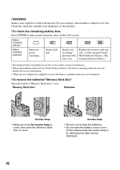
Access lamp • Be sure not to turn off the camera while the access lamp is lit, otherwise the data may not display the correct information. • When the AC Adaptor (not supplied) is used, the ... to drop the batteries. • Do not open the battery cover or turn on and check the time on the LCD screen. Do not recharge, disassemble or dispose of in once. "Memory Stick Duo" Batteries Access lamp • Make sure that the access lamp is not displayed. [ To remove the batteries...
Access lamp • Be sure not to turn off the camera while the access lamp is lit, otherwise the data may not display the correct information. • When the AC Adaptor (not supplied) is used, the ... to drop the batteries. • Do not open the battery cover or turn on and check the time on the LCD screen. Do not recharge, disassemble or dispose of in once. "Memory Stick Duo" Batteries Access lamp • Make sure that the access lamp is not displayed. [ To remove the batteries...
Service Manual
Page 1
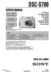
...DISASSEMBLY SERVICE NOTE BLOCK DIAGRAMS US Model Canadian Model AEP Model UK Model E Model Australian Model Chinese Model Korea Model REPAIR PARTS LIST The components identified by Kohda TEC Ne les remplacer que par une pièce portant le numéro spécifié. DIGITAL STILL CAMERA DSC-S700 9-852-183-14 Sony... EMCS Co. 2008G0800-1 © 2008.07 Published by mark 0 or dotted line with this Manual. In case of the main board, or main frame assembly failure, contact your local Sony Service Headquarter for...
...DISASSEMBLY SERVICE NOTE BLOCK DIAGRAMS US Model Canadian Model AEP Model UK Model E Model Australian Model Chinese Model Korea Model REPAIR PARTS LIST The components identified by Kohda TEC Ne les remplacer que par une pièce portant le numéro spécifié. DIGITAL STILL CAMERA DSC-S700 9-852-183-14 Sony... EMCS Co. 2008G0800-1 © 2008.07 Published by mark 0 or dotted line with this Manual. In case of the main board, or main frame assembly failure, contact your local Sony Service Headquarter for...

Service Manual
Page 4
SERVICE NOTE 1-1. Disassembly 2-1 3. Accessories 4-4 DSC-S700 - 4 - Process After Fixing Flash Error 1-1 1-2. BLOCK DIAGRAMS 3-1. Overall Block Diagram 3-1 3-2. Overall Section 4-1 4-1-2. TABLE OF CONTENTS Section Title Page 1. DISASSEMBLY 2-1. Power Block Diagram 3-2 4. REPAIR PARTS LIST 4-1. Method for Copying or Erasing the Data in blue. Main Frame Block 4-2 4-1-3. Lens Block 4-3 4-2. Ver. 1.2 2008.06 The changed portions from Ver. 1.1 are shown in Internal Memory 1-1 2. Exploded Views 4-1 4-1-1.
SERVICE NOTE 1-1. Disassembly 2-1 3. Accessories 4-4 DSC-S700 - 4 - Process After Fixing Flash Error 1-1 1-2. BLOCK DIAGRAMS 3-1. Overall Block Diagram 3-1 3-2. Overall Section 4-1 4-1-2. TABLE OF CONTENTS Section Title Page 1. DISASSEMBLY 2-1. Power Block Diagram 3-2 4. REPAIR PARTS LIST 4-1. Method for Copying or Erasing the Data in blue. Main Frame Block 4-2 4-1-3. Lens Block 4-3 4-2. Ver. 1.2 2008.06 The changed portions from Ver. 1.1 are shown in Internal Memory 1-1 2. Exploded Views 4-1 4-1-1.
Service Manual
Page 6
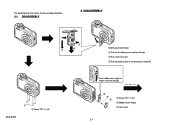
DISASSEMBLY 2. DISASSEMBLY 2 3 A 1 Battery case lid removal 1 Pull out the battery case slowly until stop 2 Put a nail into a slot 3 Pull the battery case in the direction of arrow A DSC-S700 1 1 Screw TP1.7 × 3.0 Push middle cover (right) as shown to reveal the gap. (See Page 2-2) 2 1 3 1 Screw TP1.7 × 3.0 2 Middle Cover (Right) 3 Jack Cover 2-1 The following flow chart shows the disassembly procedure. 2-1.
DISASSEMBLY 2. DISASSEMBLY 2 3 A 1 Battery case lid removal 1 Pull out the battery case slowly until stop 2 Put a nail into a slot 3 Pull the battery case in the direction of arrow A DSC-S700 1 1 Screw TP1.7 × 3.0 Push middle cover (right) as shown to reveal the gap. (See Page 2-2) 2 1 3 1 Screw TP1.7 × 3.0 2 Middle Cover (Right) 3 Jack Cover 2-1 The following flow chart shows the disassembly procedure. 2-1.
Service Manual
Page 7
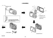
(From 2-1 Page) 1 Middle Cover (Left) 1 2. DISASSEMBLY 1 Insert the plastic tweezers into the gap between middle cover (left) and DC door to prize the middle cover (left). (See Page 2-3) 2 1 3 1 Screw TP1.7 × 3.0 2 Cabinet (Rear) Assy 3 Button Assy 1 Cabinet (Bottom) 1 DSC-S700 1 1 Cabinet (Front) Assy 2-2
(From 2-1 Page) 1 Middle Cover (Left) 1 2. DISASSEMBLY 1 Insert the plastic tweezers into the gap between middle cover (left) and DC door to prize the middle cover (left). (See Page 2-3) 2 1 3 1 Screw TP1.7 × 3.0 2 Cabinet (Rear) Assy 3 Button Assy 1 Cabinet (Bottom) 1 DSC-S700 1 1 Cabinet (Front) Assy 2-2
Service Manual
Page 8
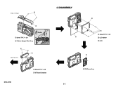
DISASSEMBLY 2 Caution Shorting jig (1kΩ / 1W) 1 Screw TP1.7 × 3.0 3 2 Cabinet (Upper) Block Assy 1 2 (See Page 2-4) 2 1 1 Screw TP1.7 × 3.0 2 LCD Holder 3 LCD 1 DSC-S700 1 Screw TP1.7 × 3.0 2 ST Board Complate 2-3 1 SW Frame Assy 1 (From 2-2 Page) 2.
DISASSEMBLY 2 Caution Shorting jig (1kΩ / 1W) 1 Screw TP1.7 × 3.0 3 2 Cabinet (Upper) Block Assy 1 2 (See Page 2-4) 2 1 1 Screw TP1.7 × 3.0 2 LCD Holder 3 LCD 1 DSC-S700 1 Screw TP1.7 × 3.0 2 ST Board Complate 2-3 1 SW Frame Assy 1 (From 2-2 Page) 2.
Service Manual
Page 9
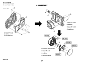
DISASSEMBLY 3 1 4 1 Screw TP1.4 × 3.0 2 Lens Assy 3 Screw TP1.7 × 3.0 4 Strap Bracket 2 HELP01 HELP02 4 1 Lens Block Protection Sheet 2 Screw TP1.4 × 3 3 CCD Assy 4 Low Pass Filter Set HELP02 HELP01 3 HELP03 1 2 2-4 Ver. 1.3 2008.07 The changed portions from Ver. 1.2 are shown in blue. 1 (From 2-3 Page) 1 Screw TP1.7 × 3.0 2 MCU Block Assy DSC-S700 2 1 2.
DISASSEMBLY 3 1 4 1 Screw TP1.4 × 3.0 2 Lens Assy 3 Screw TP1.7 × 3.0 4 Strap Bracket 2 HELP01 HELP02 4 1 Lens Block Protection Sheet 2 Screw TP1.4 × 3 3 CCD Assy 4 Low Pass Filter Set HELP02 HELP01 3 HELP03 1 2 2-4 Ver. 1.3 2008.07 The changed portions from Ver. 1.2 are shown in blue. 1 (From 2-3 Page) 1 Screw TP1.7 × 3.0 2 MCU Block Assy DSC-S700 2 1 2.
Service Manual
Page 19
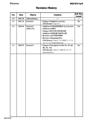
... • Revision of Regarding Fuse S.M. No. No. 302 S.M. F2 and Yes Ref. issued 1.0 2007.02 Official Release - - 1.1 2007.10 Revised-1 • Change of DISASSEMBLY for Ref. Revised : Page 2-4, HELP, 4-2, 4-3, Regarding Fuse DSC-S700 Revised : Page 4-4 1.2 2008.06 Revised-2 • Addition of Supplied accessories Yes S.M. Date History Contents S.M. Reverse Revision History 985218314.pdf Ver.
... • Revision of Regarding Fuse S.M. No. No. 302 S.M. F2 and Yes Ref. issued 1.0 2007.02 Official Release - - 1.1 2007.10 Revised-1 • Change of DISASSEMBLY for Ref. Revised : Page 2-4, HELP, 4-2, 4-3, Regarding Fuse DSC-S700 Revised : Page 4-4 1.2 2008.06 Revised-2 • Addition of Supplied accessories Yes S.M. Date History Contents S.M. Reverse Revision History 985218314.pdf Ver.
