
Warranty Card
Page 1
...For specific instructions on your product, Visit Sony's Web Site: http://www.sony.com/service Or call the Sony Customer Information Service Center 1-800-222-SONY (7669) For an accessory or part not available from state to this Limited Warranty, Sony will become the property of the original ... OR FITNESS FOR A PARTICULAR PURPOSE ON THIS PRODUCT IS LIMITED IN DURATION TO THE DURATION OF THIS WARRANTY. DIGITAL CAMERA LIMITED WARRANTY Sony Electronics Inc. ("Sony") warrants this product including supplied accessories against defects in Japan In the event of protection to be lost or ...
...For specific instructions on your product, Visit Sony's Web Site: http://www.sony.com/service Or call the Sony Customer Information Service Center 1-800-222-SONY (7669) For an accessory or part not available from state to this Limited Warranty, Sony will become the property of the original ... OR FITNESS FOR A PARTICULAR PURPOSE ON THIS PRODUCT IS LIMITED IN DURATION TO THE DURATION OF THIS WARRANTY. DIGITAL CAMERA LIMITED WARRANTY Sony Electronics Inc. ("Sony") warrants this product including supplied accessories against defects in Japan In the event of protection to be lost or ...
Operating Instructions
Page 2
...the appliance. Regulatory Information Declaration of electric shock to Subpart B of Part 15 of the FCC Rules. Telephone No.: 858-942-2230 This device complies with the limits for a Class B digital device, pursuant to radio communications. This equipment generates, uses, and can... This symbol is no guarantee that may call: Sony Customer Information Services Center 1-800-222-SONY (7669) The number below is encouraged to try to constitute a risk of Conformity Trade Name: SONY Model No.: DSC-P41, DSC-P43 Responsible Party:Sony Electronics Inc. Bernardo Dr, San Diego, CA 92127...
...the appliance. Regulatory Information Declaration of electric shock to Subpart B of Part 15 of the FCC Rules. Telephone No.: 858-942-2230 This device complies with the limits for a Class B digital device, pursuant to radio communications. This equipment generates, uses, and can... This symbol is no guarantee that may call: Sony Customer Information Services Center 1-800-222-SONY (7669) The number below is encouraged to try to constitute a risk of Conformity Trade Name: SONY Model No.: DSC-P41, DSC-P43 Responsible Party:Sony Electronics Inc. Bernardo Dr, San Diego, CA 92127...
Operating Instructions
Page 3
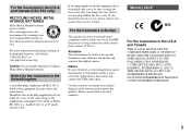
...moulded plug complying with BS 1363 is fitted to this digital camera. "Memory Stick" N50 For the Customers in the U.S.A. and Canada (DSC-P43 only) RECYCLING NICKEL METAL HYDRIDE BATTERIES Nickel Metal ... to BS 1362, (i.e., marked with this product. and Canada THIS CLASS B DIGITAL DEVICE COMPLIES WITH PART 15 OF THE FCC RULES AND THE CANADIAN ICES-003 OPERATION IS SUBJECT TO THE... the Customers in Europe This product has been tested and found compliant with your nearest Sony service station. For more information regarding recycling of this equipment for using connection cables shorter...
...moulded plug complying with BS 1363 is fitted to this digital camera. "Memory Stick" N50 For the Customers in the U.S.A. and Canada (DSC-P43 only) RECYCLING NICKEL METAL HYDRIDE BATTERIES Nickel Metal ... to BS 1362, (i.e., marked with this product. and Canada THIS CLASS B DIGITAL DEVICE COMPLIES WITH PART 15 OF THE FCC RULES AND THE CANADIAN ICES-003 OPERATION IS SUBJECT TO THE... the Customers in Europe This product has been tested and found compliant with your nearest Sony service station. For more information regarding recycling of this equipment for using connection cables shorter...
Operating Instructions
Page 6
... last image shot - Folder 59 Enlarging a portion of a still image - Slide show 61 Rotating still images - Table of contents Read this first 4 Identifying the parts 8 Getting started Preparing batteries 10 On handling of batteries 10 Charging the batteries (DSC-P43 only 11 Inserting the batteries 12 Using the AC Adaptor 15 Using your camera abroad 16...
... last image shot - Folder 59 Enlarging a portion of a still image - Slide show 61 Rotating still images - Table of contents Read this first 4 Identifying the parts 8 Getting started Preparing batteries 10 On handling of batteries 10 Charging the batteries (DSC-P43 only 11 Inserting the batteries 12 Using the AC Adaptor 15 Using your camera abroad 16...
Operating Instructions
Page 8
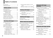
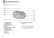
You will be unable to firmly secure the camera to tripods having longer screws, and may damage the camera. A POWER lamp (16) B POWER button (16) C Shutter button (24) D Flash (29) E Speaker (bottom surface) F Finder window G Self-timer lamp (28)/ AF illuminator (31, 109) H Lens I Microphone 8 J Tripod receptacle (bottom surface) • Use a tripod with a screw length of operation. Identifying the parts See the pages in parentheses for details of less than 5.5 mm (7/32 inch).
You will be unable to firmly secure the camera to tripods having longer screws, and may damage the camera. A POWER lamp (16) B POWER button (16) C Shutter button (24) D Flash (29) E Speaker (bottom surface) F Finder window G Self-timer lamp (28)/ AF illuminator (31, 109) H Lens I Microphone 8 J Tripod receptacle (bottom surface) • Use a tripod with a screw length of operation. Identifying the parts See the pages in parentheses for details of less than 5.5 mm (7/32 inch).

Operating Instructions
Page 54
...54 Control button Mode switch a Set the mode switch to turn spot metering on. Before operation Set (Camera) in a small area of the whole image. VGA FINE 101 P 98 Spot metering cross hair ...SAF To cancel spot metering Press B ( ) again to or . The camera calculates the best-fit exposure based on the subject's position and background brightness. The default setting...indicator) The image is multi-pattern metering. The spot metering cross hair disappears, and the camera returns to multipattern metering. • When using spot metering, to focus on the same spot...
...54 Control button Mode switch a Set the mode switch to turn spot metering on. Before operation Set (Camera) in a small area of the whole image. VGA FINE 101 P 98 Spot metering cross hair ...SAF To cancel spot metering Press B ( ) again to or . The camera calculates the best-fit exposure based on the subject's position and background brightness. The default setting...indicator) The image is multi-pattern metering. The spot metering cross hair disappears, and the camera returns to multipattern metering. • When using spot metering, to focus on the same spot...

Operating Instructions
Page 62
...and display the image you shot will be displayed at the same time as part of one image. • You cannot divide the Multi Burst image. 62 The menu appears. c Select (Rotate) with v/V, then press z. Playing back images shot in Multi Burst mode ...still images - To cancel the rotation In Step 4 or 5, select [Cancel]. • You cannot rotate protected images, movies, and Multi Burst images. • You may not be reflected depending on a camera without the Multi Burst function, the 16 frames you want to rotate images shot with b/B. Rotate Images shot when holding the camera...
...and display the image you shot will be displayed at the same time as part of one image. • You cannot divide the Multi Burst image. 62 The menu appears. c Select (Rotate) with v/V, then press z. Playing back images shot in Multi Burst mode ...still images - To cancel the rotation In Step 4 or 5, select [Cancel]. • You cannot rotate protected images, movies, and Multi Burst images. • You may not be reflected depending on a camera without the Multi Burst function, the 16 frames you want to rotate images shot with b/B. Rotate Images shot when holding the camera...

Operating Instructions
Page 101
... printer manufacturer whether the printer provides these functions. • The date may not be printed with a pointed object, then turn on the camera. indicator on the date-inserted part. The camera gets hot if you - p Consult with new ones (pages 11, 12). p The images that do not have the recording date data cannot...
... printer manufacturer whether the printer provides these functions. • The date may not be printed with a pointed object, then turn on the camera. indicator on the date-inserted part. The camera gets hot if you - p Consult with new ones (pages 11, 12). p The images that do not have the recording date data cannot...
Marketing Specifications
Page 1
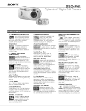
...5 separate focus areas of the frame, Sony's Multi-Point AF system can be clear. PictBridge™ Compatibility Connect to any part of the image with the supplied USB cable and print directly from the camera. Images can intelligently focus on the subject...keys. ® DSC-P41 Cyber-shot® Digital Still Camera F E AT U R E S 1/2.7" 4.1 Megapixel Super HAD™ CCD Super HAD (Hole Accumulation Diode) CCDs provide excellent image quality by allowing more light to pass to each pixel, increasing sensitivity and reducing noise. 3X Digital Zoom Sony's Precision Digital Zoom provides an ...
...5 separate focus areas of the frame, Sony's Multi-Point AF system can be clear. PictBridge™ Compatibility Connect to any part of the image with the supplied USB cable and print directly from the camera. Images can intelligently focus on the subject...keys. ® DSC-P41 Cyber-shot® Digital Still Camera F E AT U R E S 1/2.7" 4.1 Megapixel Super HAD™ CCD Super HAD (Hole Accumulation Diode) CCDs provide excellent image quality by allowing more light to pass to each pixel, increasing sensitivity and reducing noise. 3X Digital Zoom Sony's Precision Digital Zoom provides an ...
Marketing Specifications
Page 2
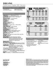
...Sony, Cyber-shot, Digital, Powerful, Transportable, Memory Stick, the Memory Stick logo, Memory Stick PRO, Smart Zoom and Super HAD, are registered trademarks of Sony. A portion of the memory is used for Sony v1.0 (Windows), Pixela™ ImageMixer VCD2 (Macintosh), SPVD-012.1 USB Driver, Cyber-shot... Supplied Software: Picture Package™ for data management functions. DSC-P41 Cyber-shot® Digital Still Camera ADDITIONAL FEATURES 3:2 Aspect Ratio Mode Clear Color/Clear Luminance NR... 1GB=940MB Actual available memory in part without notice. f5.6 Exposure Compensation:...
...Sony, Cyber-shot, Digital, Powerful, Transportable, Memory Stick, the Memory Stick logo, Memory Stick PRO, Smart Zoom and Super HAD, are registered trademarks of Sony. A portion of the memory is used for Sony v1.0 (Windows), Pixela™ ImageMixer VCD2 (Macintosh), SPVD-012.1 USB Driver, Cyber-shot... Supplied Software: Picture Package™ for data management functions. DSC-P41 Cyber-shot® Digital Still Camera ADDITIONAL FEATURES 3:2 Aspect Ratio Mode Clear Color/Clear Luminance NR... 1GB=940MB Actual available memory in part without notice. f5.6 Exposure Compensation:...
Service Manual
Page 1
... in service manual Level 3. Pages 4-50 and 5-51 Electrical parts list Pages 5-7 and 5-10 to 4-42 Mounted parts location ....... search on printed wiring boards is premised the circuit board replacement service and not intended repair inside the CH-146 and SY-101 boards. DIGITAL STILL CAMERA DSC-P41/P43 SERVICE MANUAL Ver 1.0 2004.04 Revision History How...
... in service manual Level 3. Pages 4-50 and 5-51 Electrical parts list Pages 5-7 and 5-10 to 4-42 Mounted parts location ....... search on printed wiring boards is premised the circuit board replacement service and not intended repair inside the CH-146 and SY-101 boards. DIGITAL STILL CAMERA DSC-P41/P43 SERVICE MANUAL Ver 1.0 2004.04 Revision History How...
Service Manual
Page 3
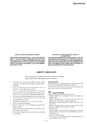
... pattern (copper foil) may also be applied to the customer and recommend their replacement. 5. DSC-P41/P43 SAFETY-RELATED COMPONENT WARNING!! REPLACE THESE COMPONENTS WITH SONY PARTS WHOSE PART NUMBERS APPEAR AS SHOWN IN THIS MANUAL OR IN SUPPLEMENTS PUBLISHED BY SONY. SAFETY CHECK-OUT After correcting the original service problem, perform the following characteristics. •...
... pattern (copper foil) may also be applied to the customer and recommend their replacement. 5. DSC-P41/P43 SAFETY-RELATED COMPONENT WARNING!! REPLACE THESE COMPONENTS WITH SONY PARTS WHOSE PART NUMBERS APPEAR AS SHOWN IN THIS MANUAL OR IN SUPPLEMENTS PUBLISHED BY SONY. SAFETY CHECK-OUT After correcting the original service problem, perform the following characteristics. •...
Service Manual
Page 4
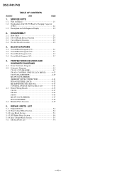
... Section 5-3 5-1-3. Description on Self-diagnosis Display 1-2 2. BLOCK DIAGRAMS 3-1. Frame Schematic Diagram 4-1 4-2. Front Cabinet Block Section 5-2 5-1-2. Flexible Boards Location 2-5 3. Overall Block Diagram (2/2 3-3 3-3. Power Block Diagram (1/2 3-5 3-4. REPAIR PARTS LIST 5-1. BT Holder Block Section 5-4 5-1-4. DSC-P41/P43 Section TABLE OF CONTENTS Title Page 1. SERVICE NOTE 1-1. Note for Repair 1-1 1-2. Circuit Boards Location 2-5 2-4. Electrical...
... Section 5-3 5-1-3. Description on Self-diagnosis Display 1-2 2. BLOCK DIAGRAMS 3-1. Frame Schematic Diagram 4-1 4-2. Front Cabinet Block Section 5-2 5-1-2. Flexible Boards Location 2-5 3. Overall Block Diagram (2/2 3-3 3-3. Power Block Diagram (1/2 3-5 3-4. REPAIR PARTS LIST 5-1. BT Holder Block Section 5-4 5-1-4. DSC-P41/P43 Section TABLE OF CONTENTS Title Page 1. SERVICE NOTE 1-1. Note for Repair 1-1 1-2. Circuit Boards Location 2-5 2-4. Electrical...

Service Manual
Page 5
... short jig, a small clip is snapped. It is possible that a wire is attached to the maximum 300 V potential. Cut and remove the part of gilt which is kept without discharging when the main power of the unit is charged up to each end of a resistor of electric shock... is caused by hand. DISCHARGING OF THE ST-098 BOARD'S CHARGING CAPACITOR (C852) The charging capacitor (C852) of connector. SECTION 1 SERVICE NOTE DSC-P41/P43 1-1. Do not insert the cable insufficiently nor crookedly. NOTE FOR REPAIR Make sure that the flat cable and flexible board are not cracked of...
... short jig, a small clip is snapped. It is possible that a wire is attached to the maximum 300 V potential. Cut and remove the part of gilt which is kept without discharging when the main power of the unit is charged up to each end of a resistor of electric shock... is caused by hand. DISCHARGING OF THE ST-098 BOARD'S CHARGING CAPACITOR (C852) The charging capacitor (C852) of connector. SECTION 1 SERVICE NOTE DSC-P41/P43 1-1. Do not insert the cable insufficiently nor crookedly. NOTE FOR REPAIR Make sure that the flat cable and flexible board are not cracked of...

Service Manual
Page 7
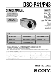
... between the two points with the short jig about 10 seconds. 2 1 Mic unit flexible: CN707 2 DC motor harness: CN602 3 Front cabinet R:1 kΩ/1 W (Part code: 1-215-869-11) ST-0958 Capacitor 1 4 2 DSC-P41/P43 HELP 3 5 4 21 1 Caution label 2 Tape (A) HELP 3 FP-853: CN702 4 FP-856: CN601 5 Lens block 3 9 2 qs 8 9 1 1 Screw (M1.7) x2 2 Microphone unit...
... between the two points with the short jig about 10 seconds. 2 1 Mic unit flexible: CN707 2 DC motor harness: CN602 3 Front cabinet R:1 kΩ/1 W (Part code: 1-215-869-11) ST-0958 Capacitor 1 4 2 DSC-P41/P43 HELP 3 5 4 21 1 Caution label 2 Tape (A) HELP 3 FP-853: CN702 4 FP-856: CN601 5 Lens block 3 9 2 qs 8 9 1 1 Screw (M1.7) x2 2 Microphone unit...

Service Manual
Page 18
... DC 10 MΩ input impedance is damaged by the heat. • Some chip part will be indicated. • Parts with part number specified. They are measured between the measurement points and ground when camera shoots color bar chart of the lens L = About 23 cm (PTB-450) ...;, MΩ=1000 kΩ. • Caution when replacing chip parts. New parts must be obtain. Note : The components identified by reference number, please include the board name. Refer to the model/destination. SCHEMATIC DIAGRAMS DSC-P41/P43 4-2. Replace only with ★ differ according to the ...
... DC 10 MΩ input impedance is damaged by the heat. • Some chip part will be indicated. • Parts with part number specified. They are measured between the measurement points and ground when camera shoots color bar chart of the lens L = About 23 cm (PTB-450) ...;, MΩ=1000 kΩ. • Caution when replacing chip parts. New parts must be obtain. Note : The components identified by reference number, please include the board name. Refer to the model/destination. SCHEMATIC DIAGRAMS DSC-P41/P43 4-2. Replace only with ★ differ according to the ...

Service Manual
Page 19
... 82 D803 SML-310LTT86 (SELE TIMER/RECORDING) R816 820 SIGNAL PATH VIDEO SIGNAL Y/CHROMA REC 4-7 CD-501 BOARD 7 8 9 10 11 DSC-P41/P43 12 Q804 R807 1k DTC144EMT2L SWITCH 0 R4.5/P0 R806 2200 C808 XX 16V 12 11 10 9 8 7 6 5 4 3 2...FLEXIBLE PAGE 4-12 of CCD Imager • The CD-501 board mounted as a repair part is not included in CD-501 complete board. In addition, ensure that the receiver is ...mounted by static electricity from its structure, handle it carefully like for the camera section. • As the CCD imager may be measured because this is not covered...
... 82 D803 SML-310LTT86 (SELE TIMER/RECORDING) R816 820 SIGNAL PATH VIDEO SIGNAL Y/CHROMA REC 4-7 CD-501 BOARD 7 8 9 10 11 DSC-P41/P43 12 Q804 R807 1k DTC144EMT2L SWITCH 0 R4.5/P0 R806 2200 C808 XX 16V 12 11 10 9 8 7 6 5 4 3 2...FLEXIBLE PAGE 4-12 of CCD Imager • The CD-501 board mounted as a repair part is not included in CD-501 complete board. In addition, ensure that the receiver is ...mounted by static electricity from its structure, handle it carefully like for the camera section. • As the CCD imager may be measured because this is not covered...

Service Manual
Page 21
...mVp-p H IC201 LCD DRIVE IC201 CM7103L43-T4 3 IC201 r; SCHEMATIC DIAGRAMS SW-420 BOARD DSC-P41/P43 For Schematic Diagram • Refer to page 4-43 for safety. Ne les remplacer... I J K 05 R260 1k S262 RESET KEY_AD1 KEY_AD0 MODE_DIAL0 KEY_AD2 MOVIE S261 (MODE SWITCH) STILL R253 1200 VIEW R262 1200 1Pin R252 1500 R251 3300 R256 1500 S251 (FLASH) S256 S254...S257 T SIGNAL PATH VIDEO SIGNAL CHROMA REC PB The components identified by mark 0 or dotted line with part number specified. 4-2. Les composants identifiés par une marque 0 sont critiques pour la sécurité...
...mVp-p H IC201 LCD DRIVE IC201 CM7103L43-T4 3 IC201 r; SCHEMATIC DIAGRAMS SW-420 BOARD DSC-P41/P43 For Schematic Diagram • Refer to page 4-43 for safety. Ne les remplacer... I J K 05 R260 1k S262 RESET KEY_AD1 KEY_AD0 MODE_DIAL0 KEY_AD2 MOVIE S261 (MODE SWITCH) STILL R253 1200 VIEW R262 1200 1Pin R252 1500 R251 3300 R256 1500 S251 (FLASH) S256 S254...S257 T SIGNAL PATH VIDEO SIGNAL CHROMA REC PB The components identified by mark 0 or dotted line with part number specified. 4-2. Les composants identifiés par une marque 0 sont critiques pour la sécurité...

Service Manual
Page 22
... R858 1M 5 321 NC GND 0 OUT 5 0 4 IN VDD IC851 FLASH CONTROL IC851 TND721MH5-S-TL-E 10 05 The components identified by mark 0 or dotted line with part number specified. Ne les remplacer que par une piéce portant le numéro spécifié. DSC-P41/P43 4-2.
... R858 1M 5 321 NC GND 0 OUT 5 0 4 IN VDD IC851 FLASH CONTROL IC851 TND721MH5-S-TL-E 10 05 The components identified by mark 0 or dotted line with part number specified. Ne les remplacer que par une piéce portant le numéro spécifié. DSC-P41/P43 4-2.

Service Manual
Page 23
...D 05 STATIC_GND SIGNAL PATH VIDEO SIGNAL Y/CHROMA REC PB AUDIO SIGNAL 1 11 10 12 6 7 MEMORY STICK MEMORY STICK MS BOARD FP-860 FLEXIBLE BOARD DSC-P41/P43 For Schematic Diagram • Refer to page 4-47 for printed wiring board. 1 2 3 4 5 MS BOARD (FP-861 FLEXIBLE BOARD) A MEMORY...J001 DC IN STATIC_GND CN752 1 VCC 2 D3 D+ 4 ID 5 GND BT001 LITHIUM BATTERY 1 2 3 4 SPSP+ 6 7 (USB) DSC-P43 J002 A/V OUT (MONO) SP901 SPEAKER 05 The components identified by mark 0 or dotted line with part number specified. Ne les remplacer que par une piéce portant le numéro sp...
...D 05 STATIC_GND SIGNAL PATH VIDEO SIGNAL Y/CHROMA REC PB AUDIO SIGNAL 1 11 10 12 6 7 MEMORY STICK MEMORY STICK MS BOARD FP-860 FLEXIBLE BOARD DSC-P41/P43 For Schematic Diagram • Refer to page 4-47 for printed wiring board. 1 2 3 4 5 MS BOARD (FP-861 FLEXIBLE BOARD) A MEMORY...J001 DC IN STATIC_GND CN752 1 VCC 2 D3 D+ 4 ID 5 GND BT001 LITHIUM BATTERY 1 2 3 4 SPSP+ 6 7 (USB) DSC-P43 J002 A/V OUT (MONO) SP901 SPEAKER 05 The components identified by mark 0 or dotted line with part number specified. Ne les remplacer que par une piéce portant le numéro sp...


