
Warranty Card
Page 1
... or consequential damages, or allow limitations on how to obtain warranty service for your product, Visit Sony's Web Site: http://www.sony.com/service Or call : 1-800-488-SONY (7669) Repair / Replacement Warranty: This Limited Warranty shall apply to any product or parts determined to backup any... OR FITNESS FOR A PARTICULAR PURPOSE ON THIS PRODUCT IS LIMITED IN DURATION TO THE DURATION OF THIS WARRANTY. DIGITAL CAMERA LIMITED WARRANTY Sony Electronics Inc. ("Sony") warrants this Limited Warranty for a period of one (1) year from the original date of purchase of the product...
... or consequential damages, or allow limitations on how to obtain warranty service for your product, Visit Sony's Web Site: http://www.sony.com/service Or call : 1-800-488-SONY (7669) Repair / Replacement Warranty: This Limited Warranty shall apply to any product or parts determined to backup any... OR FITNESS FOR A PARTICULAR PURPOSE ON THIS PRODUCT IS LIMITED IN DURATION TO THE DURATION OF THIS WARRANTY. DIGITAL CAMERA LIMITED WARRANTY Sony Electronics Inc. ("Sony") warrants this Limited Warranty for a period of one (1) year from the original date of purchase of the product...
Operating Instructions
Page 4
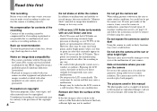
...occur. However, there may be careful not to record or play back properly. This is not possible due to malfunction, sometimes beyond repair. Do not get the camera wet When taking pictures outdoors in the rain or under similar conditions, be some tiny black points and/or bright points (white, ...as examples of data loss, always copy (back up) data to sand or dust Using the camera in this manual are reproduced images, and are not actual images shot using the camera. Do not expose the camera to a disk. Back up recommendation To avoid the potential risk of pictures in sandy or ...
...occur. However, there may be careful not to record or play back properly. This is not possible due to malfunction, sometimes beyond repair. Do not get the camera wet When taking pictures outdoors in the rain or under similar conditions, be some tiny black points and/or bright points (white, ...as examples of data loss, always copy (back up) data to sand or dust Using the camera in this manual are reproduced images, and are not actual images shot using the camera. Do not expose the camera to a disk. Back up recommendation To avoid the potential risk of pictures in sandy or ...

Operating Instructions
Page 104
...two digits (indicated by ss) will differ depending on the "Memory Stick." A camera malfunction that you cannot reverse has occurred. Contact your camera's hardware. is not still functioning well after trying the countermeasure a couple of the camera on the camera again. cannot be repaired. The camera cannot...displays the condition of times, the camera may need to be used with your Sony dealer or local authorized Sony service facility. times. An unformatted "Memory Stick" Format the "Memory Stick" (page 43). If your camera is inserted. Self-diagnosis display -If...
...two digits (indicated by ss) will differ depending on the "Memory Stick." A camera malfunction that you cannot reverse has occurred. Contact your camera's hardware. is not still functioning well after trying the countermeasure a couple of the camera on the camera again. cannot be repaired. The camera cannot...displays the condition of times, the camera may need to be used with your Sony dealer or local authorized Sony service facility. times. An unformatted "Memory Stick" Format the "Memory Stick" (page 43). If your camera is inserted. Self-diagnosis display -If...

Operating Instructions
Page 111
... cloth to 104°F)). Touch the camera with a dry cloth. This moisture condensation may condense inside the lens, you will be unable to malfunction and sometimes this malfunction cannot be repaired. To prevent moisture condensation When bringing the camera from a cold to the hot outdoors..., etc. Note that exceed this may cause the camera to record clear images. Sand or dust may cause a malfunction...
... cloth to 104°F)). Touch the camera with a dry cloth. This moisture condensation may condense inside the lens, you will be unable to malfunction and sometimes this malfunction cannot be repaired. To prevent moisture condensation When bringing the camera from a cold to the hot outdoors..., etc. Note that exceed this may cause the camera to record clear images. Sand or dust may cause a malfunction...
Service Manual
Page 1
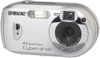
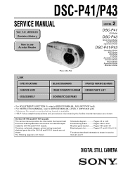
... 3. DSC-P41/P43 SERVICE MANUAL Ver 1.0 2004.04 Revision History How to use Acrobat Reader Photo: DSC-P43 2 LEVEL DSC-P41 US Model DSC-P43 Hong Kong Model Tourist Model Japanese Model DSC-P41/P43 Canadian...REPAIR PARTS LIST DISASSEMBLY SCHEMATIC DIAGRAMS • For ADJUSTMENTS (SECTION 6), refer to SERVICE MANUAL, ADJ (987674351.pdf). • For INSTRUCTION MANUAL, refer to SERVICE MANUAL, LEVEL 1 (987674341.pdf). • Reference No. Therefore, schematic diagram, printed wiring board and electrical parts list of processing the flexible boards/harnesses are shown. DIGITAL STILL CAMERA...
... 3. DSC-P41/P43 SERVICE MANUAL Ver 1.0 2004.04 Revision History How to use Acrobat Reader Photo: DSC-P43 2 LEVEL DSC-P41 US Model DSC-P43 Hong Kong Model Tourist Model Japanese Model DSC-P41/P43 Canadian...REPAIR PARTS LIST DISASSEMBLY SCHEMATIC DIAGRAMS • For ADJUSTMENTS (SECTION 6), refer to SERVICE MANUAL, ADJ (987674351.pdf). • For INSTRUCTION MANUAL, refer to SERVICE MANUAL, LEVEL 1 (987674341.pdf). • Reference No. Therefore, schematic diagram, printed wiring board and electrical parts list of processing the flexible boards/harnesses are shown. DIGITAL STILL CAMERA...
Service Manual
Page 3
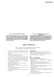
...before releasing the set to ensure that were installed during repairing. • Do not touch the soldering iron on the same conductor of your repair for unauthorized replacement parts, particularly transistors, that no lead.... NE REMPLACER CES COMPOSANTS QUE PAR DES PIÈSES SONY DONT LES NUMÉROS SONT DONNÉS DANS CE MANUEL OU DANS LES SUPPÉ...mark (LF) indicating the solder contains no wires are "pinched" or contact high-wattage resistors. 3. DSC-P41/P43 SAFETY-RELATED COMPONENT WARNING!! COMPONENTS IDENTIFIED BY MARK 0 OR DOTTED LINE WITH MARK 0 ON ...
...before releasing the set to ensure that were installed during repairing. • Do not touch the soldering iron on the same conductor of your repair for unauthorized replacement parts, particularly transistors, that no lead.... NE REMPLACER CES COMPOSANTS QUE PAR DES PIÈSES SONY DONT LES NUMÉROS SONT DONNÉS DANS CE MANUEL OU DANS LES SUPPÉ...mark (LF) indicating the solder contains no wires are "pinched" or contact high-wattage resistors. 3. DSC-P41/P43 SAFETY-RELATED COMPONENT WARNING!! COMPONENTS IDENTIFIED BY MARK 0 OR DOTTED LINE WITH MARK 0 ON ...
Service Manual
Page 4
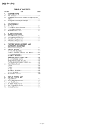
... 4-35 CD-501 4-37 SW-420 4-43 ST-098 4-45 MS (FP-861 FLEXIBLE 4-47 FP-860 FLEXIBLE 4-48 4-4. Exploded Views 5-2 5-1-1. DSC-P41/P43 Section TABLE OF CONTENTS Title Page 1. PRINTED WIRING BOARDS AND SCHEMATIC DIAGRAMS 4-1. Rear Cabinet Block Section 5-5 5-2. SERVICE NOTE 1-1. Discharging of the ST...MICROPHONE UNIT (MA-001 4-33 CONTROL SWITCH BLOCK (RL51510 4-34 4-3. Electrical Parts List 5-6 - 4 - Flow Chart 2-1 2-2. BLOCK DIAGRAMS 3-1. Note for Repair 1-1 1-2. REPAIR PARTS LIST 5-1. Power Block Diagram (2/2 3-7 4. Circuit Boards Location 2-5 2-4.
... 4-35 CD-501 4-37 SW-420 4-43 ST-098 4-45 MS (FP-861 FLEXIBLE 4-47 FP-860 FLEXIBLE 4-48 4-4. Exploded Views 5-2 5-1-1. DSC-P41/P43 Section TABLE OF CONTENTS Title Page 1. PRINTED WIRING BOARDS AND SCHEMATIC DIAGRAMS 4-1. Rear Cabinet Block Section 5-5 5-2. SERVICE NOTE 1-1. Discharging of the ST...MICROPHONE UNIT (MA-001 4-33 CONTROL SWITCH BLOCK (RL51510 4-34 4-3. Electrical Parts List 5-6 - 4 - Flow Chart 2-1 2-2. BLOCK DIAGRAMS 3-1. Note for Repair 1-1 1-2. REPAIR PARTS LIST 5-1. Power Block Diagram (2/2 3-7 4. Circuit Boards Location 2-5 2-4.

Service Manual
Page 5
... to prevent electrical shock. 1 kΩ/1 W Discharging the Capacitor Short-circuit between the positive and the negative terminals of bent at wire of connector. NOTE FOR REPAIR Make sure that a wire is charged up to each end of a resistor of electric shock by hand. R:1 kΩ/1 W (Part code: 1-215-869-11) ST-0958... preparing the short jig, a small clip is handled by this high voltage when the capacitor is attached to the maximum 300 V potential. SECTION 1 SERVICE NOTE DSC-P41/P43 1-1.
... to prevent electrical shock. 1 kΩ/1 W Discharging the Capacitor Short-circuit between the positive and the negative terminals of bent at wire of connector. NOTE FOR REPAIR Make sure that a wire is charged up to each end of a resistor of electric shock by hand. R:1 kΩ/1 W (Part code: 1-215-869-11) ST-0958... preparing the short jig, a small clip is handled by this high voltage when the capacitor is attached to the maximum 300 V potential. SECTION 1 SERVICE NOTE DSC-P41/P43 1-1.

Service Manual
Page 18
...8486;, MΩ=1000 kΩ. • Caution when replacing chip parts. SCHEMATIC DIAGRAMS DSC-P41/P43 4-2. SCHEMATIC DIAGRAMS THIS NOTE IS COMMON FOR SCHEMATIC DIAGRAMS (In addition to waveforms...of capacitor Case Size External dimensions (mm) • Constants of (+,-) B LINE. • C: adjustment for repair. • A: VIDEO SIGNAL (ANALOG) • A: AUDIO SIGNAL (ANALOG) • A: VIDEO/AUDIO SIGNAL.... • Chip resistors are measured between the measurement points and ground when camera shoots color bar chart of DC 10 MΩ input impedance is printed in...
...8486;, MΩ=1000 kΩ. • Caution when replacing chip parts. SCHEMATIC DIAGRAMS DSC-P41/P43 4-2. SCHEMATIC DIAGRAMS THIS NOTE IS COMMON FOR SCHEMATIC DIAGRAMS (In addition to waveforms...of capacitor Case Size External dimensions (mm) • Constants of (+,-) B LINE. • C: adjustment for repair. • A: VIDEO SIGNAL (ANALOG) • A: AUDIO SIGNAL (ANALOG) • A: VIDEO/AUDIO SIGNAL.... • Chip resistors are measured between the measurement points and ground when camera shoots color bar chart of DC 10 MΩ input impedance is printed in...

Service Manual
Page 19
... If the CCD imager has been replaced, carry out all the adjustments for the camera section. • As the CCD imager may be measured because this is mounted ... it carefully like for Replacement of CCD Imager • The CD-501 board mounted as a repair part is not included in CD-501 complete board. In addition, ensure that the receiver is...) R815 82 D803 SML-310LTT86 (SELE TIMER/RECORDING) R816 820 SIGNAL PATH VIDEO SIGNAL Y/CHROMA REC 4-7 CD-501 BOARD 7 8 9 10 11 DSC-P41/P43 12 Q804 R807 1k DTC144EMT2L SWITCH 0 R4.5/P0 R806 2200 C808 XX 16V 12 11 10 9 8 7 6 5 4 3 2 1 ...
... If the CCD imager has been replaced, carry out all the adjustments for the camera section. • As the CCD imager may be measured because this is mounted ... it carefully like for Replacement of CCD Imager • The CD-501 board mounted as a repair part is not included in CD-501 complete board. In addition, ensure that the receiver is...) R815 82 D803 SML-310LTT86 (SELE TIMER/RECORDING) R816 820 SIGNAL PATH VIDEO SIGNAL Y/CHROMA REC 4-7 CD-501 BOARD 7 8 9 10 11 DSC-P41/P43 12 Q804 R807 1k DTC144EMT2L SWITCH 0 R4.5/P0 R806 2200 C808 XX 16V 12 11 10 9 8 7 6 5 4 3 2 1 ...

Service Manual
Page 35
Link EXPLODED VIEWS A FRONT CABINET BLOCK SECTION B LENS BLOCK SECTION C D BT HOLDER BLOCK SECTION REAR CABINET BLOCK SECTION Link CD-501 BOARD MS BOARD ELECTRICAL PARTS LIST B ST-0985 BOARD C C SW-420 BOARD D ACCESSORIES DSC-P41/P43 NOTE 5. REPAIR PARTS LIST NOTE: Characters A to Z of the electrical parts list indicate location of exploded views in which the desired part is shown.
Link EXPLODED VIEWS A FRONT CABINET BLOCK SECTION B LENS BLOCK SECTION C D BT HOLDER BLOCK SECTION REAR CABINET BLOCK SECTION Link CD-501 BOARD MS BOARD ELECTRICAL PARTS LIST B ST-0985 BOARD C C SW-420 BOARD D ACCESSORIES DSC-P41/P43 NOTE 5. REPAIR PARTS LIST NOTE: Characters A to Z of the electrical parts list indicate location of exploded views in which the desired part is shown.

Service Manual
Page 36
... each case, u: µ, for safety. Ne les remplacer que par une pièce portant le numéro spécifié. 5-1 REPAIR PARTS LIST SECTION 5 REPAIR PARTS LIST DSC-P41/P43 NOTE: • -XX, -X mean standardized parts, so they may be different from the original one. • Items marked "*" are not stocked...
... each case, u: µ, for safety. Ne les remplacer que par une pièce portant le numéro spécifié. 5-1 REPAIR PARTS LIST SECTION 5 REPAIR PARTS LIST DSC-P41/P43 NOTE: • -XX, -X mean standardized parts, so they may be different from the original one. • Items marked "*" are not stocked...

Service Manual
Page 37
REPAIR PARTS LIST 5-1. No. 5 6 7 8 M901 Part No. DSC-P41/P43 5. Description X-2021-517-1 CABINET (FRONT) ASSY (450) (P41) X-3954-373-1 CABINET (FRONT) ASSY (510) (P43) 3-080-977-01 TRIPOD 3-080-204-21 SCREW, TAPPING, P2 3-090-844-01 WINDOW (510), OVF Ref. FRONT ...
REPAIR PARTS LIST 5-1. No. 5 6 7 8 M901 Part No. DSC-P41/P43 5. Description X-2021-517-1 CABINET (FRONT) ASSY (450) (P41) X-3954-373-1 CABINET (FRONT) ASSY (510) (P43) 3-080-977-01 TRIPOD 3-080-204-21 SCREW, TAPPING, P2 3-090-844-01 WINDOW (510), OVF Ref. FRONT ...

Service Manual
Page 38
...-01 SHEET (510), CD 2-109-995-01 SHEET (510), LCD IC801 A-7112-263-A CCD BLOCK ASSY (CCD IMAGER) (Note 1, 2) 5-3 REPAIR PARTS LIST 5-1-2. No. 51 52 53 54 55 Part No. LENS BLOCK SECTION DSC-P41/P43 59 58 52 51 57 61 CD-501 60 IC801 54 (Note 1, 2) 55 53 56 Ref. 5. Ref.
...-01 SHEET (510), CD 2-109-995-01 SHEET (510), LCD IC801 A-7112-263-A CCD BLOCK ASSY (CCD IMAGER) (Note 1, 2) 5-3 REPAIR PARTS LIST 5-1-2. No. 51 52 53 54 55 Part No. LENS BLOCK SECTION DSC-P41/P43 59 58 52 51 57 61 CD-501 60 IC801 54 (Note 1, 2) 55 53 56 Ref. 5. Ref.

Service Manual
Page 39
...not supplied 117 101 ns 102 113 112 ST-098 103 C852 108 106 110 109 SY-101 114 106 MS 116 107 115 DSC-P43 111 (including CP900 (CH-146 board)) ns SP901 104 % BT001 BT901 105 ns 106 ! 106 : BT001 (BATTERY, ...107 108 109 110 111 Part No. Description A-1059-808-A SY-101 BOARD, COMPLETE (SERVICE) (including CP900 (CH-146 board)) (P41) 1-860-199-11 FP-859 FLEXIBLE BOARD 1-860-192-11 FP-852 FLEXIBLE BOARD 3-941-343-21 TAPE (A) 2-067-931-01 SHEET...Ne les remplacer que par une pièce portant le numéro spécifié. DSC-P41/P43 5. REPAIR PARTS LIST 5-1-3.
...not supplied 117 101 ns 102 113 112 ST-098 103 C852 108 106 110 109 SY-101 114 106 MS 116 107 115 DSC-P43 111 (including CP900 (CH-146 board)) ns SP901 104 % BT001 BT901 105 ns 106 ! 106 : BT001 (BATTERY, ...107 108 109 110 111 Part No. Description A-1059-808-A SY-101 BOARD, COMPLETE (SERVICE) (including CP900 (CH-146 board)) (P41) 1-860-199-11 FP-859 FLEXIBLE BOARD 1-860-192-11 FP-852 FLEXIBLE BOARD 3-941-343-21 TAPE (A) 2-067-931-01 SHEET...Ne les remplacer que par une pièce portant le numéro spécifié. DSC-P41/P43 5. REPAIR PARTS LIST 5-1-3.

Service Manual
Page 40
... 0 sont critiques pour la sécurité. REAR CABINET BLOCK SECTION ns: not supplied ns 151 156 154 152 151 SW-420 153 D901 LCD901 DSC-P41/P43 155 Ref. No. 151 152 153 154 154 Part No. Ne les remplacer que par une pièce portant le numéro... spécifié. Part No. REPAIR PARTS LIST 5-1-4. Description 3-078-890-11 SCREW, TAPPING A-7113-097-A SW-420 BOARD, COMPLETE 3-090-794-01 SHEET, RESET X-2021-518-1 CABINET (REAR) ASSY (450...
... 0 sont critiques pour la sécurité. REAR CABINET BLOCK SECTION ns: not supplied ns 151 156 154 152 151 SW-420 153 D901 LCD901 DSC-P41/P43 155 Ref. No. 151 152 153 154 154 Part No. Ne les remplacer que par une pièce portant le numéro... spécifié. Part No. REPAIR PARTS LIST 5-1-4. Description 3-078-890-11 SCREW, TAPPING A-7113-097-A SW-420 BOARD, COMPLETE 3-090-794-01 SHEET, RESET X-2021-518-1 CABINET (REAR) ASSY (450...


