
Service Manual
Page 1
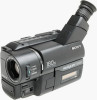
... Ver 1.0 1999.01 Photo : CCD-TR516 US Model Canadian Model CCD-TR416/TR516/TR716 CCD-TRV16/TRV36/TRV43/TRV46 E Model CCD-TR315/TR416PK/TR516PK CCD-TRV16/TRV16PK/TRV36PK/ TRV46/TRV46PK Hong Kong Model CCD-TRV16/TRV46 Taiwan Model CCD-TRV16 Brazilian Model CCD-TR315/TR416 CCD-TRV16 B MECHANISM Photo : CCD-TRV46 NTSC SPECIFICATIONS For MECHANISM ADJUSTMENTS... NTSC color, EIA standards Usable cassette 8mm video format cassette CCD-TR315/TR416/TR416PK CCD-TRV16/TRV16PK : standard 8 CCD-TR516/TR516PK/TR716 CCD-TRV36/TRV36PK/TRV43/TRV46/ TRV46PK : Hi8 Recording / Playback time (using 120 min.
... Ver 1.0 1999.01 Photo : CCD-TR516 US Model Canadian Model CCD-TR416/TR516/TR716 CCD-TRV16/TRV36/TRV43/TRV46 E Model CCD-TR315/TR416PK/TR516PK CCD-TRV16/TRV16PK/TRV36PK/ TRV46/TRV46PK Hong Kong Model CCD-TRV16/TRV46 Taiwan Model CCD-TRV16 Brazilian Model CCD-TR315/TR416 CCD-TRV16 B MECHANISM Photo : CCD-TRV46 NTSC SPECIFICATIONS For MECHANISM ADJUSTMENTS... NTSC color, EIA standards Usable cassette 8mm video format cassette CCD-TR315/TR416/TR416PK CCD-TRV16/TRV16PK : standard 8 CCD-TR516/TR516PK/TR716 CCD-TRV36/TRV36PK/TRV43/TRV46/ TRV46PK : Hi8 Recording / Playback time (using 120 min.

Service Manual
Page 2
...using LCD CCD-TRV16/TRV16PK/TRV36/ TRV36PK : 3.1 W CCD-TRV43/TRV46/TRV46PK : 3.2 W Viewfinder CCD-TRV16/TRV16PK/TRV36/ TRV36PK : 2.5 W CCD-TRV43/TRV46/TRV46PK : 2.6 W Operating temperature 32°FC to 104°F (C0°C to 40°C) Storage temperature -4°FC to 140°F (-20°C to change without notice. • Abbreviation Canadian model is ... soldering or unsoldering. LES COMPOSANTS IDENTIFIÉS PAR UNE MARQUE ! NE REMPLACER CES COMPOSANTS QUE PAR DES PIÉCES SONY DONT LES NUMÉROS SONT DONNÉS DANS CE MANUEL OU DANS LES SUPPLÉMENTS PUBLIÉS PAR...
...using LCD CCD-TRV16/TRV16PK/TRV36/ TRV36PK : 3.1 W CCD-TRV43/TRV46/TRV46PK : 3.2 W Viewfinder CCD-TRV16/TRV16PK/TRV36/ TRV36PK : 2.5 W CCD-TRV43/TRV46/TRV46PK : 2.6 W Operating temperature 32°FC to 104°F (C0°C to 40°C) Storage temperature -4°FC to 140°F (-20°C to change without notice. • Abbreviation Canadian model is ... soldering or unsoldering. LES COMPOSANTS IDENTIFIÉS PAR UNE MARQUE ! NE REMPLACER CES COMPOSANTS QUE PAR DES PIÉCES SONY DONT LES NUMÉROS SONT DONNÉS DANS CE MANUEL OU DANS LES SUPPLÉMENTS PUBLIÉS PAR...

Service Manual
Page 3
... abbreviated as TW. Table for difference of function Model CCDTR315 CCDTR416 Destination E,BR US,CND Classification View finder Remote commander (RMT-708) Hi8 Standard 8 Lens (Digital ZOOM) Video light CCD Steadyshot Laser Link LCD panel TYPE E B/W G G ¬ 180X G 510 G G G Color G G ¬ 180X G 510 G G G ...SE451,452,IC451 ¬ : with VC-215board IC751 2.5 inch : TRV series only Model Destination Classification View finder Remote commander (RMT-708) Hi8 Standard 8 Lens (Digital ZOOM) Video light CCD Steadyshot Laser Link LCD panel CCDTRV43 US,CND B/W ¬ ¬ G 330x ...
... abbreviated as TW. Table for difference of function Model CCDTR315 CCDTR416 Destination E,BR US,CND Classification View finder Remote commander (RMT-708) Hi8 Standard 8 Lens (Digital ZOOM) Video light CCD Steadyshot Laser Link LCD panel TYPE E B/W G G ¬ 180X G 510 G G G Color G G ¬ 180X G 510 G G G ...SE451,452,IC451 ¬ : with VC-215board IC751 2.5 inch : TRV series only Model Destination Classification View finder Remote commander (RMT-708) Hi8 Standard 8 Lens (Digital ZOOM) Video light CCD Steadyshot Laser Link LCD panel CCDTRV43 US,CND B/W ¬ ¬ G 330x ...

Service Manual
Page 4
... abbreviated as BR. Hong Kong model is abbreviated as HK. Taiwan model is already installed in your camcorder. 5 Size AA (R6) battery for Remote Commander (2) CCD-TR516/TR516PK/TR716 CCD-TRV36/TRV36PK/TRV43/TRV46/TRV46PK 6 A / V connecting cable (1) 7 Shoulder strap (1) 8 Video P6-15P HB tape CCD-TR416: US/TR516: US/TR716:US CCD-TRV16:US/TRV36:US/TRV43:US...
... abbreviated as BR. Hong Kong model is abbreviated as HK. Taiwan model is already installed in your camcorder. 5 Size AA (R6) battery for Remote Commander (2) CCD-TR516/TR516PK/TR716 CCD-TRV36/TRV36PK/TRV43/TRV46/TRV46PK 6 A / V connecting cable (1) 7 Shoulder strap (1) 8 Video P6-15P HB tape CCD-TR416: US/TR516: US/TR716:US CCD-TRV16:US/TRV36:US/TRV43:US...

Service Manual
Page 7
... drum operations Remove the battery or power cable, connect, and perform operations from the beginning. Note : Use the remote commander RM-95 only for the model without the focus dial.
... drum operations Remove the battery or power cable, connect, and perform operations from the beginning. Note : Use the remote commander RM-95 only for the model without the focus dial.

Service Manual
Page 8
...Cabinet (L) Block 2-4 2-8. Removal of CCD-TRV36/TRV43/TRV46. Servo Block Diagram 3-12 3-5. VTR/Camera Control Block Diagram 3-9 3-4. Audio Block Diagram 3-19 3-7. Removal of Backup No 6 3-3. BLOCK DIAGRAMS 3-1. B/W EVF Block Diagram (B/W EVF model 3-29 3-10. Switching of VF... PROGRAM AE function 1-9 Focusing manually 1-9 Enjoying picture effect 1-10 Adjusting the exposure 1-10 Superimposing a title 1-11 Making your camcorder abroad 1-17 Truoble check 1-17 Self-diagnosis display 1-18 Identifying the parts 1-18 Warning Indicators 1-20 2-1. Self-diagnosis function...
...Cabinet (L) Block 2-4 2-8. Removal of CCD-TRV36/TRV43/TRV46. Servo Block Diagram 3-12 3-5. VTR/Camera Control Block Diagram 3-9 3-4. Audio Block Diagram 3-19 3-7. Removal of Backup No 6 3-3. BLOCK DIAGRAMS 3-1. B/W EVF Block Diagram (B/W EVF model 3-29 3-10. Switching of VF... PROGRAM AE function 1-9 Focusing manually 1-9 Enjoying picture effect 1-10 Adjusting the exposure 1-10 Superimposing a title 1-11 Making your camcorder abroad 1-17 Truoble check 1-17 Self-diagnosis display 1-18 Identifying the parts 1-18 Warning Indicators 1-20 2-1. Self-diagnosis function...

Service Manual
Page 9
...(Servo) Board 4-38 • VC-215 (Audio) Board 4-41 • VL-20/21 (Video Light) Board (Video Light model) .... 4-45 • VC-215 (IR Transmitter) Board 4-46 • VC-215 (Mode Control) Board 4-49 • ...5-16 3-2. Angular Velocity Sensor Sensitivity Check 5-22 1-4. PRINTED WIRING BOARDS AND SCHEMATIC DIAGRAMS 4-1. Preparations 5-2 1-1-3. Subject 5-5 1-1-4. Color Electronic Viewfinder System Adjustments (CCD-TR416/TR416PK/TR516/TR516PK/TR716) ...... 5-23 1. Camera System Adjustments 5-14 1. Flange Back Adjustment 5-16 3-1. 4. VCO adjustment (PD-107 board 5-30...
...(Servo) Board 4-38 • VC-215 (Audio) Board 4-41 • VL-20/21 (Video Light) Board (Video Light model) .... 4-45 • VC-215 (IR Transmitter) Board 4-46 • VC-215 (Mode Control) Board 4-49 • ...5-16 3-2. Angular Velocity Sensor Sensitivity Check 5-22 1-4. PRINTED WIRING BOARDS AND SCHEMATIC DIAGRAMS 4-1. Preparations 5-2 1-1-3. Subject 5-5 1-1-4. Color Electronic Viewfinder System Adjustments (CCD-TR416/TR416PK/TR516/TR516PK/TR716) ...... 5-23 1. Camera System Adjustments 5-14 1. Flange Back Adjustment 5-16 3-1. 4. VCO adjustment (PD-107 board 5-30...

Service Manual
Page 10
...Hi8) switching (Hi8 model 5-39 3-1-8. Input/output selection check 5-43 8. Switching Position Adjustment (VC-215 board) .... 5-46 3-4. Video System Adjustments 5-47 1. 28 MHz Origin Oscillation Adjustment (VC-215 board 5-47 2. Y OUT Level Adjustment (VC-215 board 5-49 5. Standerd8 REC L Level Adjustment (VC-215 board) (CCD-TR315/TR416/TR416PK CCD-TRV16... f0 Adjustment (VC-215 board 5-50 7. Standerd8 REC Y Current Adjustment (VC-215 board) (CCD-TR315/TR416/TR416PK CCD-TRV16/TRV16PK 5-52 9. IR Audio Deviation Adjustment (VC-215 board) ... 5-57 3-6. Monaural Audio System...
...Hi8) switching (Hi8 model 5-39 3-1-8. Input/output selection check 5-43 8. Switching Position Adjustment (VC-215 board) .... 5-46 3-4. Video System Adjustments 5-47 1. 28 MHz Origin Oscillation Adjustment (VC-215 board 5-47 2. Y OUT Level Adjustment (VC-215 board 5-49 5. Standerd8 REC L Level Adjustment (VC-215 board) (CCD-TR315/TR416/TR416PK CCD-TRV16... f0 Adjustment (VC-215 board 5-50 7. Standerd8 REC Y Current Adjustment (VC-215 board) (CCD-TR315/TR416/TR416PK CCD-TRV16/TRV16PK 5-52 9. IR Audio Deviation Adjustment (VC-215 board) ... 5-57 3-6. Monaural Audio System...

Service Manual
Page 31
... COVER (TR series) CF-60 BOARD (TR series) LCD BLOCK (TR series) 2-14. REMOVAL OF FRONT PANEL BLOCK AND VIDEO LIGHT BLOCK -Video light models- CCD-TR315/TR416/TR416PK CCD-TRV16/TRV16PK 1Two screws (M2 x 4) 2Cabinet (LT) 1Two screws (M2x4) 2Cabinet (N) Claw 3Screw (M2 x 4) 6Front panel block 8Video light block 5Two screws (M2 x 4) 4Screw...
... COVER (TR series) CF-60 BOARD (TR series) LCD BLOCK (TR series) 2-14. REMOVAL OF FRONT PANEL BLOCK AND VIDEO LIGHT BLOCK -Video light models- CCD-TR315/TR416/TR416PK CCD-TRV16/TRV16PK 1Two screws (M2 x 4) 2Cabinet (LT) 1Two screws (M2x4) 2Cabinet (N) Claw 3Screw (M2 x 4) 6Front panel block 8Video light block 5Two screws (M2 x 4) 4Screw...

Service Manual
Page 32
REMOVAL OF VF-99 AND CRT ASSEMBLY (B/W view finder model CCD-TR315 and TRV series) 1 Tilt-up the EVF block to the direction of arrow A. 3 Remove the EVF rear cabinet assembly to the direction of arrow B. 5 ... Three claws 7 VF light interception sheet 9 LB-54 board 8 VF-120 board 2-3. REMOVAL OF LB-54, VF-119 AND VF-120 BOARDS (Color view finder model CCD-TR416/TR416PK/TR516/TR516PK/TR716) 1 Tilt-up the EVF block to the direction of arrow B. 7 CRT assembly 6 CRT holder assmebly 2 Three screws (M2 x 3) B A 4 VF electrostatic...
REMOVAL OF VF-99 AND CRT ASSEMBLY (B/W view finder model CCD-TR315 and TRV series) 1 Tilt-up the EVF block to the direction of arrow A. 3 Remove the EVF rear cabinet assembly to the direction of arrow B. 5 ... Three claws 7 VF light interception sheet 9 LB-54 board 8 VF-120 board 2-3. REMOVAL OF LB-54, VF-119 AND VF-120 BOARDS (Color view finder model CCD-TR416/TR416PK/TR516/TR516PK/TR716) 1 Tilt-up the EVF block to the direction of arrow B. 7 CRT assembly 6 CRT holder assmebly 2 Three screws (M2 x 3) B A 4 VF electrostatic...

Service Manual
Page 34
... switch in the direction of arrow with pushing the claw. 2Flexible connector CN935, 10P Two claws 1Screw (M2 x 3) Two claws 2-9. CCD-TR315/TR416/TR416PK CCD-TRV16/TRV16PK 7Two screws (M2 x 3) 8Shoe bracket No video light models 3Screw (M2 x 3) 5FP-623 flexible board CN501, 16P 6Lens flexible board CN551, 23P CN909 4Zoom lens block 2-10...
... switch in the direction of arrow with pushing the claw. 2Flexible connector CN935, 10P Two claws 1Screw (M2 x 3) Two claws 2-9. CCD-TR315/TR416/TR416PK CCD-TRV16/TRV16PK 7Two screws (M2 x 3) 8Shoe bracket No video light models 3Screw (M2 x 3) 5FP-623 flexible board CN501, 16P 6Lens flexible board CN551, 23P CN909 4Zoom lens block 2-10...

Service Manual
Page 38
... forcus (MF-8500) FP-620...TR716 & TRV series only FP-220 CIRCUIT BOARDS LOCATION LB-54...Color EVF models only VF-119...Color EVF models only (Back light) (Color EVF) VF-120...Color EVF models only (Color EVF) DD-117 (Power) CF-60...TR series only (Control) VL-21...TR516/TR516PK/TR716 VL.../TRV36PK/TRV43/ TRV46/TRV46PK (Video light) PJ-90...TR series PJ-91...TRV series (AV Out) VF-99...B/W EVF models only (B/W EVF) CD-210...TR series only CD-211...TRV series only (CCD imager) PD-107...TRV series only RGB decoder, LCD, LCD drive, Back light VC-215 Camera, Y/C prosessor, IN/OUT...
... forcus (MF-8500) FP-620...TR716 & TRV series only FP-220 CIRCUIT BOARDS LOCATION LB-54...Color EVF models only VF-119...Color EVF models only (Back light) (Color EVF) VF-120...Color EVF models only (Color EVF) DD-117 (Power) CF-60...TR series only (Control) VL-21...TR516/TR516PK/TR716 VL.../TRV36PK/TRV43/ TRV46/TRV46PK (Video light) PJ-90...TR series PJ-91...TRV series (AV Out) VF-99...B/W EVF models only (B/W EVF) CD-210...TR series only CD-211...TRV series only (CCD imager) PD-107...TRV series only RGB decoder, LCD, LCD drive, Back light VC-215 Camera, Y/C prosessor, IN/OUT...

Service Manual
Page 51
...are few cases that the part isn't mounted in this diagram. • Chip transistor C Q BE VF-99...B/W EVF models only (B/W EVF) CD-210...TR series only CD-211...TRV series only (CCD imager) PD-107...TRV series only RGB decoder, LCD, LCD drive, Back light CF-61...TRV series only (Control)... of Fig. ital multimeter (DC 10MΩ). f pattern box. a and the B BA erminal output waveform) tron beam ned frame Blue CRT picture frame e on this model is printed on monitor TV) CD-210/211 BOARD (SIDE B) C CD-210/211 BOARD (SIDE A) B 3 21 A 1-672-458- 11 1-672-464- 11 21 09 1 2...
...are few cases that the part isn't mounted in this diagram. • Chip transistor C Q BE VF-99...B/W EVF models only (B/W EVF) CD-210...TR series only CD-211...TRV series only (CCD imager) PD-107...TRV series only RGB decoder, LCD, LCD drive, Back light CF-61...TRV series only (Control)... of Fig. ital multimeter (DC 10MΩ). f pattern box. a and the B BA erminal output waveform) tron beam ned frame Blue CRT picture frame e on this model is printed on monitor TV) CD-210/211 BOARD (SIDE B) C CD-210/211 BOARD (SIDE A) B 3 21 A 1-672-458- 11 1-672-464- 11 21 09 1 2...

Service Manual
Page 62
by rk er ne la ne olor EVF models only ht) F-120...Color EVF models only olor EVF) CF-60...TR series only (Control) VL-21... TR516/TR516PK/TR716 VL-22... TRV36/TRV36PK/TRV43/ TRV46/TRV46PK (Video light) PJ-90...TR series PJ-91...TRV series (AV Out) PB 57 3.58 MHz IC751 7 58 2usec IC751 15 59 0.09usec IC751 16 60 0.09usec IC751 22 61 H IC751 41 0.25Vp-p 0.5Vp-p 0.34Vp-p 0.7Vp-p 0.5Vp-p
by rk er ne la ne olor EVF models only ht) F-120...Color EVF models only olor EVF) CF-60...TR series only (Control) VL-21... TR516/TR516PK/TR716 VL-22... TRV36/TRV36PK/TRV43/ TRV46/TRV46PK (Video light) PJ-90...TR series PJ-91...TRV series (AV Out) PB 57 3.58 MHz IC751 7 58 2usec IC751 15 59 0.09usec IC751 16 60 0.09usec IC751 22 61 H IC751 41 0.25Vp-p 0.5Vp-p 0.34Vp-p 0.7Vp-p 0.5Vp-p

Service Manual
Page 66
There are few cases that the part isn't mounted in this model is printed on this diagram. • Chip transistor C Q BE LB-54...Color EVF models only VF-119...Color EVF models only (Back light) (Color EVF) VF-120...Color EVF models only (Color EVF) DD-117 (Power) CF-60...TR series only (Control) VL-21... TR516/TR516PK/TR716 VL-22... TRV36/TRV36PK/TRV43/ TRV46/TRV46PK (Video light) PJ-90...TR series PJ-91...TRV series (AV Out) M L O MIC (PLUG IN POWER) 4 MA-345/346 BOARD (SIDE B) E VTR D POWER CAMERA C B A 09 1 2 3 • For Printed Wiring Boards.
There are few cases that the part isn't mounted in this model is printed on this diagram. • Chip transistor C Q BE LB-54...Color EVF models only VF-119...Color EVF models only (Back light) (Color EVF) VF-120...Color EVF models only (Color EVF) DD-117 (Power) CF-60...TR series only (Control) VL-21... TR516/TR516PK/TR716 VL-22... TRV36/TRV36PK/TRV43/ TRV46/TRV46PK (Video light) PJ-90...TR series PJ-91...TRV series (AV Out) M L O MIC (PLUG IN POWER) 4 MA-345/346 BOARD (SIDE B) E VTR D POWER CAMERA C B A 09 1 2 3 • For Printed Wiring Boards.

Service Manual
Page 72
... S5804 T5701 C-9 D-10 C-11 D-9 A-5 A-5 C-4 D-4 D-4 C-4 C-4 D-4 C-4 D-4 C-1 C-1 A-1 A-1 A-7 A-1 B-7 B-7 B-9 A-4 A-4 D-1 C-1 B-1 A-1 B-7 PD-107 BOARD (SIDE B) D LCD BRIGHT (+) LCD BRIGHT (-) C 8 765 4 3 2 1 B VOLUME (+) A VOLUME (-) 09 1 2 VF-99...B/W EVF models only (B/W EVF) CD-210...TR series only CD-211...TRV series only (CCD imager) PD-107...TRV series only RGB decoder, LCD, LCD drive, Back light 15 3 4 • For Printed Wiring Boards...
... S5804 T5701 C-9 D-10 C-11 D-9 A-5 A-5 C-4 D-4 D-4 C-4 C-4 D-4 C-4 D-4 C-1 C-1 A-1 A-1 A-7 A-1 B-7 B-7 B-9 A-4 A-4 D-1 C-1 B-1 A-1 B-7 PD-107 BOARD (SIDE B) D LCD BRIGHT (+) LCD BRIGHT (-) C 8 765 4 3 2 1 B VOLUME (+) A VOLUME (-) 09 1 2 VF-99...B/W EVF models only (B/W EVF) CD-210...TR series only CD-211...TRV series only (CCD imager) PD-107...TRV series only RGB decoder, LCD, LCD drive, Back light 15 3 4 • For Printed Wiring Boards...

Service Manual
Page 82
... the micro processor IC in the adjusting remote commander is not the new micro processor (UPD7503GC56-12), the pages cannot be switched. CCD-TR315/TR416/TR416PK/TR516/TR516PK/TR716 CCD-TRV16/TRV16PK/TRV36/TRV36PK/TRV43/TRV46/TRV46PK SECTION 5 ADJUSTMENTS 5-1. List of the battery terminal using adhesive tape, etc. J-1 J-2 J-3 ...J-12 Name Filter for color temperature correction (C14) ND filter 1.0 ND filter 0.3 Pattern box PTB-450 Color bar chart for distinction functions of models and classification 1-1. No. In this case, replace with the new micro processor (8-759-148-35).
... the micro processor IC in the adjusting remote commander is not the new micro processor (UPD7503GC56-12), the pages cannot be switched. CCD-TR315/TR416/TR416PK/TR516/TR516PK/TR716 CCD-TRV16/TRV16PK/TRV36/TRV36PK/TRV43/TRV46/TRV46PK SECTION 5 ADJUSTMENTS 5-1. List of the battery terminal using adhesive tape, etc. J-1 J-2 J-3 ...J-12 Name Filter for color temperature correction (C14) ND filter 1.0 ND filter 0.3 Pattern box PTB-450 Color bar chart for distinction functions of models and classification 1-1. No. In this case, replace with the new micro processor (8-759-148-35).

Service Manual
Page 83
... Camera Power ON mode", the camera power can be lost . 1-1-2. After completing adjustments, reset these data. VC-215 board CN916 (18P 0.5mm) 3) The video light model need not be disassembled. 1) Connect the equipment for the data on the history use (total drum rotation time etc. ) will be turned on history of...
... Camera Power ON mode", the camera power can be lost . 1-1-2. After completing adjustments, reset these data. VC-215 board CN916 (18P 0.5mm) 3) The video light model need not be disassembled. 1) Connect the equipment for the data on the history use (total drum rotation time etc. ) will be turned on history of...

Service Manual
Page 84
... jack, and set the HOLD switch to the "ADJ" side, or press the battery switch of the battery terminal using adhesive tape, etc. Fig. 5-1-3. TR MODEL Color monitor Vector scope Terminated at 75 Ω Lens block CD-210 board CN401 Extension cable(16P) (J-6082-357-A) VL-21 board CN151 VIDEO terminal...
... jack, and set the HOLD switch to the "ADJ" side, or press the battery switch of the battery terminal using adhesive tape, etc. Fig. 5-1-3. TR MODEL Color monitor Vector scope Terminated at 75 Ω Lens block CD-210 board CN401 Extension cable(16P) (J-6082-357-A) VL-21 board CN151 VIDEO terminal...

Service Manual
Page 85
... LANC jack, and set the HOLD switch to the "ADJ" side, or press the battery switch of the battery terminal using adhesive tape, etc. TRV MODEL Color monitor Vector scope Terminated at 75 Ω Lens block CD-211 board CN401 Extension cable(16P) (J-6082-357-A) VL-22 board CN151 VIDEO terminal...
... LANC jack, and set the HOLD switch to the "ADJ" side, or press the battery switch of the battery terminal using adhesive tape, etc. TRV MODEL Color monitor Vector scope Terminated at 75 Ω Lens block CD-211 board CN401 Extension cable(16P) (J-6082-357-A) VL-22 board CN151 VIDEO terminal...

